1
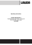
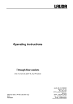
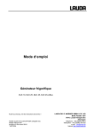
Operating Instructions Ethernet USB Module LRZ 921 These instructions only apply in conjunction with the operating instructions for the LAUDA thermostatic unit in which the module is installed. Dated 14.03.2013 Translation of the German Original Operating Instructions Edition 03/2013 a11 Replaces Edition 02/2013a10 LAUDA DR. R. WOBSER GMBH & CO. KG Postfach 1251 97912 Lauda-Königshofen Germany YAAE0026 Phone: +49 9343/ 503-0 Fax: +49 9343/ 503-222 e-mail [email protected] Internet http://www.lauda.de Remote Maintenance Table of contents 1 Safety ............................................................................................................................................................ 4 1.1 1.2 2 Explanation of the symbols .................................................................................................................... 4 Safety information .................................................................................................................................. 4 General remarks .......................................................................................................................................... 5 2.1 2.2 2.3 2.4 Description of the module ...................................................................................................................... 5 Intended application ............................................................................................................................... 5 Use other than that intended .................................................................................................................. 5 Responsibility of the operating body - safety information ...................................................................... 5 3 Glossary ....................................................................................................................................................... 6 4 Installing the module................................................................................................................................... 6 5 Menu structure of the Ethernet USB module ........................................................................................... 7 6 Remote Maintenance................................................................................................................................... 8 6.1 6.2 6.3 7 Activating the remote maintenance (Data transfer off/on) ..................................................................... 8 Checking the registration (Registration no/ok) ....................................................................................... 8 LAN settings (network settings) ............................................................................................................. 9 Process interface....................................................................................................................................... 10 7.1 Activating the process interface (Process SST on/off) ....................................................................... 10 7.1.1 Deactivating the DHCP client........................................................................................................ 10 7.1.2 Entering the port ........................................................................................................................... 10 7.1.3 Activating the process interface .................................................................................................... 11 7.2 Putting the process interface into operation on the PC ....................................................................... 11 7.3 Supported equipment lines .................................................................................................................. 11 8 Fault rectification....................................................................................................................................... 12 9 LAUDA Service Constant Temperature Equipment ............................................................................... 14 10 Disposal of the packaging ........................................................................................................................ 14 Supplementary information ............................................................................................................................. 15 17/05/2013/ YAAE0026 Table of contents 3 Remote Maintenance 1 Safety 1.1 Explanation of the symbols 1.2 Note: Here, something in particular needs the reader's attention. Reference Refers to further information in other chapters. Safety information • Read through the operating instructions carefully. They contain important information for working with this module. If you have any queries, please contact LAUDA Service Constant Temperature Equipment ( 9). • Follow all the directions in these operating instructions. Only in this way is the correct procedure ensured when working with the module. • These instructions only apply in conjunction with the operating instructions for the LAUDA thermostatic unit in which the module is installed. • The Ethernet USB module may only be operated with approved LAUDA thermostatic units. The list of approved thermostatic units can be found in the supplementary information at the end of these operating instructions. • Make sure that the module is only operated by instructed specialist personnel of full legal age. • Do not make technical modifications to the module. Infringements in this respect invalidate the warranty. • Have service and repair work carried out only by specialists. 4 Safety 17/05/2013/ YAAE0026 Remote Maintenance 2 General remarks 2.1 Description of the module This module offers customers the possibility of monitoring and controlling their temperature control processes, which are undertaken using a LAUDA thermostatic unit, through a process interface by means of a LAUDA interface instruction set. A further function of the module is the remote maintenance of the LAUDA thermostatic units via the Internet. The thermostatic unit connected to the remote maintenance service can be diagnosed quickly and in detail by the qualified LAUDA service technician. This means that when a problem arises, the cause can be found and remedied quickly. Article Order number Ethernet USB module LRZ 921 1 4 2 3 1 2 Network socket RJ 45 (8-pole) USB socket 2.0 type A Fig.: Front view of the module 3 USB socket 2.0 type B 4 Orange and yellow LED Remarks Interfaces 2 and 3 do not currently function. Technical modifications reserved. Intended application 2.2 The Ethernet USB module is exclusively intended for operation with LAUDA thermostatic units. The list of supported thermostatic units can be found in the supplementary information at the end of these operating instructions. The module must only be operated as intended and under the conditions stated in these operating instructions. Any other operating mode is not regarded as intended use. Replacement of the micro-SD card is only permissible by LAUDA service technicians. Use other than that intended 2.3 The device must not be used... for medical/pharmaceutical applications when sited outdoors. • • 2.4 Responsibility of the operating body - safety information The operating body is responsible for the qualifications of the operating personnel. • • • • • The module must only be configured, installed, maintained and repaired by specialist personnel. Persons operating the module must be instructed in their work by a specialist. Make sure that specialist personnel and operators have read and understood the operating instructions. The module must be used as intended. The operating instructions of the thermostatic unit with which this module is to be operated continue to be applicable. 17/05/2013/ YAAE0026 General remarks 5 Remote Maintenance 3 Glossary Glossary DHCP client (Dynamic Host Configuration Protocol client) DHCP facilitates the automatic integration of a module with an Ethernet interface into an existing network. Consequently, manual adaptation of programs or hardware on the existing network is no longer necessary. Local mask Local (subnet) masks are used to adapt the rigid class distribution of IP addresses flexibly in networks and computers to the actual circumstances. Gateway Various networks are linked together using gateways. Here, an IP address is granted, over which a gateway in the local network can be reached. DNS server (Domain Name Service) The domain name service is a database in which mainly information on names and IP addresses of computers are stored. For example, a web address or URL (Uniform Resource Locator) is resolved for an IP address. In the Ethernet USB module an IP address of the DNS server is given which is present in the connected network. Local IP address The local IP address is an address of the Ethernet USB module in the local network. Telegrams are addressed over the Internet using this address. If the DHCP client is deactivated, the local IP address, local mask, gateway and DNS server must be manually set up (configured). For the manual configuration first contact your own IT department. IP version This gives information about the Internet standard: IPv4 or IPv6. MAC (Media Access Control) Media access control is an internationally unique hardware address which is used for the unambiguous identification of the device in an Ethernet network. NTP (Network Time Protocol) Network time protocol is a standard for synchronizing the time and date in the networks. Port A port is taken to be a number which is used for establishing the link between two network subscribers. The port is part of the network address. In the Ethernet USB module the port can be used from the released "dynamic ports" range. This lies between 49152 and 65535. 4 Installing the module The installation of a module is described in the operating instructions for the Integral XT. Order number YAWE 0028, Chapter 8.1 Installation of modules. LAUDA operating instructions are available as downloads under the following link: http://www.lauda.de/ further to DOWNLOAD and Operating instructions. http://www.lauda.de/hosting/lauda/website_de.nsf/urlnames/betriebsanleitungen 6 Glossary 17.05.13/ YAAE0026 Remote Maintenance 5 Menu structure of the Ethernet USB module All existing menu points are shown. Menu points which cannot be realized are automatically masked out. Menu off on Byte1. Byte2. Byte3. Byte4 Module Serial Command Profibus SmartCool Switching contacts Ethernet Byte1. Byte2. Byte3. Byte4 LAN settings Process interface off/on Transmission off/on Registration no/ok DHCP client Local IP address Local mask Gateway DNS server IP version MAC Port Byte1. Byte2. Byte3. Byte4 on off 54321 Byte1. Byte2. Byte3. Byte4 IPv4 00-50-C2-XX-XX-XX on off Figure 1: Menu structure for LAN settings. 17.05.13/ YAAE0026 Menu structure 7 Remote Maintenance 6 Remote Maintenance The remote maintenance enables the service technician to make a qualified observation and diagnosis of the parameters of the thermostatic unit. Once the device for remote maintenance has been released by LAUDA Service, the remote maintenance can be activated or deactivated by the customer in the menu of the Command remote control. With active remote maintenance (Data transfer on) certain parameters from the thermostatic unit are transferred to a server. These parameters contribute to the thermostatic unit being diagnosed quickly and in detail. 6.1 Activating the remote maintenance (Data transfer off/on) On first switching on the device with an Ethernet USB module, the data transfer must be activated for remote maintenance. Command Data transfer Ethernet Offline Pump Menu LAN settings Process SST Data transfer Registration End Tset off off no Tfix − Connect the Ethernet USB module to your Ethernet network using a network cable. − Open the device parameter menu using the Menu softkey. − With and or you move from Modules Ethernet Online to Data transfer off . − Press the key to activate the data transfer. The menu point switches Data transfer on . The menu point Registration switches within 5 min. to Registration ok . On switching off the device the status of Data transfer (off/on) is stored and retrieved from the memory on switching on again. If the Ethernet USB module is installed in another LAUDA thermostatic unit, the activation of the remote maintenance must be repeated. 6.2 Checking the registration (Registration no/ok) Once you have connected the thermostat to the Internet and activated the data transfer, the registration should automatically switch over to Registration ok within 5 min. If no changeover occurs, check the following points: • Is the network cable correctly connected? Does the yellow LED on the Ethernet socket flash? • Is the DHCP client set to on ? (If DHCP is supported). Menu Modules Ethernet Online LAN settings DHCP client . • Are the network settings (LAN settings) correctly configured? (If fixed network settings are used). If still no connection is made to the Internet, contact our Service Department ( 9). 8 Remote maintenance 17/05/2013/ YAAE0026 Remote Maintenance 6.3 LAN settings (network settings) The DHCP client facilitates automatic configuration of the network settings for the Internet. In the factory settings the DHCP client is switched on. Prerequisite: A DHCP server must be present (ask your IT department about this). If no DHCP server is present or the IP addresses have to be granted on a fixed basis, configure the points below and set the DHCP client to off . Request the required data from your IT department or have the IT personnel set the data. Local IP address used in the connected network, e.g. 192.168.1.30. Local mask , e.g. 255.255.255.0. Gateway is an IP address of a gateway, which connects the internal network to the public network, e.g. 192.168.1.1. DNS server is an IP address at which the DNS database can be accessed. In the IP version menu point the appropriate IP version is set, i.e. IPv4 or IPv6. Remark: Currently only IPv4 is supported. In the MAC menu point the MAC address of the Ethernet module is displayed. A port number between 49152 and 65535 is entered in the Port menu point. This number is used for establishing the connection to the process interface Process SST . 17/05/2013 YAAE0026 Remote maintenance 9 Remote Maintenance 7 Process interface The process interface enables the customer to control and monitor the connected thermostatic unit via the Ethernet USB module and WinTherm or the customer's own application*. *The data transfer takes place using the LAUDA interface instruction set. For a detailed list refer to the operating instructions of the thermostatic unit used in the chapter "RS232/485 interface". Activating the process interface (Process SST on/off) 7.1 The menu point DHCP client must be deactivated for operating the process interface. In the factory settings the DHCP client is switched on. 7.1.1 Deactivating the DHCP client Before the DHCP client can be deactivated, a network setting must be carried out. Refer to Chapter 6.3 LAN settings (network settings) in this respect. Command − DHCP client Local IP address Local mask Gateway DNS server IP version MAC Port Pump Menu DHCP client − off on The device parameter menu is opened using the Menu softkey. − With and or you move from Modules Ethernet LAN settings to DHCP client . − For deactivation you select the menu point off and confirm your selection by pressing the button . The DHCP client is deactivated if you have previously carried out the network setup. End Tset Tfix On switching off the device the status of the setting of DHCP client (off/on) and the network configuration is stored and retrieved from the memory on switching on again. If the Ethernet USB module is installed in another LAUDA thermostatic unit, the setting must be repeated. 7.1.2 Entering the port Command − DHCP client Local IP address Local mask Gateway DNS server IP version MAC Port 54321 Port − Open the device parameter menu using the Menu softkey. − With and or you move from Modules Ethernet LAN settings to Port . − Here, you enter the desired port number. Minimum value 49152, maximum 65535. − Confirm your selection with the button . The port number set at the factory is 54321. Pump 10 Menu End Tset Tfix Process interface 17.05.13/ YAAE0026 Remote Maintenance When the device is switched off, the entered port number is retained so that on switching on again the value does not need to be re-entered. 7.1.3 Activating the process interface Command − Ethernet Offline Pump Menu LAN settings Process SST End Tset Process SST − Connect the Ethernet USB module to your Ethernet network using a network cable. − Open the device parameter menu using the Menu softkey. − With and or you move from Modules Ethernet Online to Process SST . − For activation you select the menu point Process SST and confirm your selection by off Tfix pressing the button twice. If Process SST off was displayed in the menu point previously, the menu point switches to on . If Process SST on was present before the selection, switching to off occurs. If you previously deactivated DHCP client , Process SST is activated. To establish a connection to the thermostatic unit refer to Chapter 7.2. On switching off the device the status of the process interface is not retained, so that on switching on again the activation has to be repeated. 7.2 Putting the process interface into operation on the PC The communication between the PC and the Ethernet USB module takes place by means of a virtual COM port. The generation and interfacing of a virtual COM port to the LAN is supported by special drivers. If you have no driver of your own, you can use the "Virtual Serial Port Emulator", abbreviated to VSPE. When configuring the driver, the IP address and the port of the Ethernet USB module must be entered. During the driver configuration the thermostatic unit to which a link is to be set up must be switched on. The Ethernet USB module must already be configured. When using the VSPE, you can use instructions from us for the installation and correct configuration of the driver. Request the instructions from our sales staff or download them from our web site http://www.lauda.de/. 7.3 The company LAUDA DR. R. WOBSER GMBH & CO. KG provides no guarantee nor support for the "Virtual Serial Port Emulator" driver. Contact the manufacturer directly for any queries and deficiencies regarding the driver. Supported equipment lines The equipment lines supported by the process interface can be seen in the supplementary information at the end of these operating instructions. 17.05.13/ YAAE0026 Process interface 11 Remote Maintenance 8 Fault rectification Before you contact the LAUDA Service Constant Temperature Equipment, check whether the you can rectify the faults yourself with the hints described in Table 1. Faults: Alarms are relevant to safety. Pump, heating and chiller are automatically shut down. Alarms: Warnings: Warnings are not relevant to safety. The device continues to run. Error: Errors are relevant to safety. If a fault occurs, the pump, heater and cooling unit switch off automatically. Switch off the unit at the mains switch. If the fault recurs after switching on the unit, contact LAUDA Service Constant Temperature Equipment ( 9). Table 1: Faults which the user may possibly be able to rectify 12 Fault Description Possible remedy No connection No connection can be established between PC and thermostat Make sure that the configuration of the process interface (port number, IP address) matches the configuration in the driver on the PC. If the configuration is correct, restart the thermostatic unit and activate the process SST. Error 9 PHY no start When this error occurs, restart the LAUDA thermostatic unit. If the error is still present, contact LAUDA Service Constant Temperature Equipment ( 9). Error 24 Diff. Thermostat Line It is not possible to use the Ethernet module with this equipment line. Check whether the software you are using for the Ethernet USB module supports your equipment line (refer to the supplementary information, Chapter 1 "Supported equipment lines"). Warning 3 SD: not opened When this warning occurs, restart the LAUDA thermostatic unit. If the warning is still present, contact LAUDA Service Constant Temperature Equipment ( 9). Warning 7 SD: data loss This indicates that some data from the remote maintenance are lost. The cause of the error: 1. The data are not being transferred to the server (e.g. data transfer has been switched off); 2. There has been no connection to the server for a longer time period (here other communication errors are also active). Warning 33 Name server failed Check whether the network cable is correctly connected. Does the yellow LED on the Ethernet USB module flash? If you are using manual settings of the DHCP client, check the configuration of the DNS server. Make sure that the set IP address is correct. If everything is correctly connected and configured and the warning is still present, contact LAUDA Service Constant Temperature Equipment ( 9). Fault rectification 17.05.13/ YAAE0026 Remote Maintenance Fault Description Possible remedy Warning 38 TCP connect timeout 39 TCP data timeout 40 TCP disconnected 46 Unknown SOAP error 52 SD: not read 54 SD: not written If these warnings persist over a lengthy period of time, contact LAUDA Service Constant Temperature Equipment ( 9). Warning 47 NTP unavailable Make sure that an NTP server (for more information refer to Chapter 3) is available and that it is functioning. Warning 49 DHCP unavailable Check whether a DHCP server is present in your network and that it functions. Warning 50 IP address conflict If you are using manual settings of the network, check whether the entered IP address already exists in the network. Try another IP address. With all other faults 17.05.13/ YAAE0026 Contact LAUDA Service Constant Temperature Equipment ( 9). Fault rectification 13 Remote Maintenance 9 LAUDA Service Constant Temperature Equipment When ordering replacement parts state the serial number from the rating label; this helps to avoid queries and incorrect deliveries. The serial number is composed as follows, e.g. LRZ921-13-0001 LRZ921 = Order number 13 = Year of manufacture 2013 0001 = Incremental numeration Your contact for maintenance and expert service support. LAUDA Service Constant Temperature Equipment Phone: +49 9343 / 503-236 (English and German) Fax: +49 9343 / 503-283 e-mail [email protected] We are available at any time for queries and ideas! LAUDA DR. R. WOBSER GMBH & CO. KG Postfach 1251 97912 Lauda-Königshofen Germany Phone: +49 9343/ 503-0 Fax: +49 9343 / 503-222 e-mail [email protected] Internet http://www.lauda.de/ 10 Disposal of the packaging The following applies to Europe: The disposal of the packaging must be carried out according to the EC Directive 94/62/EC. For Germany the Packaging Act (VerpackV) applies. 14 Service 17.05.13/ YAAE0026 Supplementary Information for the Operating Instructions Ethernet USB Module LRZ 921 Dated 20.02.2013 Page 1 of 4 1 Remote Maintenance ....................................................................................................................................... 1 1.1 1.2 2 Supported equipment lines ......................................................................................................................... 1 Supported modules ..................................................................................................................................... 1 Process interface.............................................................................................................................................. 2 2.1 2.2 Supported equipment lines ......................................................................................................................... 2 Supported modules ..................................................................................................................................... 2 V:\EKst\Prozesse\Betriebsanleitung\Zubehör\3.Word\1.aktuell\YAAE0026_a7_Zusatz-Fernwartung_13-02-20.docx Page 2 of 4 1 Remote Maintenance 1.1 Supported equipment lines All supported equipment lines for the remote maintenance are shown in the following Table 1. Table 1 Supported LAUDA equipment lines Software version of the Ethernet USB module from Y 1.09 1.2 Supported equipment lines Integral XT Device types All device types. Exceptions are: XT 4 H XT 4 HW XT 8 H XT 8 HW Supported modules In the following Table 2 all supported modules are listed in relation to the software version of the Ethernet USB module. Table 2 Supported modules Software version of the Ethernet USB module from Y 1.09 Y 1.11 Y 1.12 Y 1.13, Y 1.14 Supported modules Control Safety Command Cool Pump_0 and Pump_1 Control Safety Command Cool Pump_0 and Pump_1 Analog Digital Control Safety Command Cool Pump_0 and Pump_1 Analog Digital Control Safety Command Cool Pump_0 and Pump_1 Analog Digital Requirements on the software of the supported module from 2.31 from 2.11 from 3.14 from 2.14 from 2.08 from 2.31 from 2.11 from 3.16 from 2.14 from 2.08 all all from 2.31 from 2.11 from 3.18 from 2.14 from 2.08 all all from 2.31 from 2.11 from 3.19 from 2.14 from 2.08 all all V:\EKst\Prozesse\Betriebsanleitung\Zubehör\3.Word\1.aktuell\YAAE0026_a7_Zusatz-Fernwartung_13-02-20.docx Page 2 of 4 2 Process interface 2.1 Supported equipment lines All supported equipment lines for the process interface are shown in the following Table 3. Table 3 Supported equipment lines for the process interface Software version of the Ethernet USB module from Y 1.14 2.2 Supported equipment lines Integral XT Device types All device types. Exceptions are: XT 4 H XT 4 HW XT 8 H XT 8 HW Supported modules In the following Table 4 all supported modules are listed in relation to the software version of the Ethernet USB module. Table 4 Supported modules for the process interface Software version of the Ethernet USB module Y 1.11 Supported modules Control Safety Command Cool Pump_0 and Pump_1 Analog Digital Serial Requirements on the software of the supported module from 2.31 from 2.11 from 3.23 from 2.14 from 2.08 all all from 3.06 V:\EKst\Prozesse\Betriebsanleitung\Zubehör\3.Word\1.aktuell\YAAE0026_a7_Zusatz-Fernwartung_13-02-20.docx Page 3 of 4