1
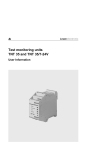
Motor control unit DCM31
DCM31
1 or 2-leaf gate control for 24VDC drive units each 11A
Installation & operating instructions for electricians & (electrically) skilled
persons
Please keep these instructions in a safe place to ensure they are available should you
have any questions at a later date.
Not intended for issuing to end customers (users)!
-
-
An instruction manual / instruction for use must be prepared for the user for “their
application”.
A handover declaration and/or acceptance inspection certificate must be prepared.
Any possible hazards must be pointed out to the user.
Operation and servicing/maintenance of the unit must be explained.
Important! Please read these instructions before putting into service!
24.04.2006 JT
D:\FILES\MOTORST UND ZUB\DCM31\28505401_DCM31_EN.DOC
Motor control unit DCM31
Contents:
1)
2)
3)
4)
5)
6)
7)
8)
2 / 35
Intended Purpose .................................................................................................3
a) Requirements.................................................................................................3
b) Legal requirements ........................................................................................3
c) Technical qualification requirements ..............................................................4
d) Important safety instructions ..........................................................................4
Installation.............................................................................................................5
a) Suitable installation site..................................................................................5
b) Installation......................................................................................................5
Brief Explanation of Terms Used ..........................................................................5
a) Abbreviations used in the instructions............................................................6
Connections..........................................................................................................7
a) Terminals .......................................................................................................7
b) Radio............................................................................................................10
Controls / Displays ..............................................................................................11
a) LEDs next to the display ..............................................................................11
b) LEDs behind terminals .................................................................................11
c) Jumper [J1] ..................................................................................................11
d) 2 x 7-Segment: Display menus and states...................................................12
e) Function of the keys .....................................................................................13
Putting into Service / Programming ....................................................................14
a) Using menu function ....................................................................................14
b) Gate type default setting ..............................................................................14
c) Programming ...............................................................................................14
d) Deleting the force values and travel paths ...................................................14
e) Teaching runs / learn force values ...............................................................14
f) Reset the control unit (factory setting)..........................................................15
Menu Table.........................................................................................................16
Functional Description ........................................................................................20
a) Radio module ...............................................................................................20
b) Input A and B and radio receiver..................................................................20
c) Automatic closing .........................................................................................21
d) Partial opening (TÖ).....................................................................................21
e) Active leaf (GF) ............................................................................................22
f) Closing delay: (in 2-motor mode) .................................................................22
g) Opening delay: (in 2 motor mode)................................................................22
h) Smooth start.................................................................................................22
i) Smooth travel-out length and motor voltage ................................................22
j) Motor voltage over travel path......................................................................23
k) Smooth stop.................................................................................................23
l) Light / warning light ......................................................................................23
m) Emergency stop ...........................................................................................23
n) Electricity stop / obstruction detection ..........................................................24
o) Force values ................................................................................................24
p) Closing edge safety device (SE) ..................................................................24
q) Photoelectric barrier input (LS) ....................................................................25
r) Release........................................................................................................25
s) Close after leaving the photoelectric barrier.................................................25
t) 1 /2 leaf mode ..............................................................................................25
u) Relay output OUT ........................................................................................26
Motor control unit DCM31
v) Running time limit.........................................................................................26
w) Type of limit switch.......................................................................................26
x) Service mode ...............................................................................................27
y) Trip counter..................................................................................................27
9) Error Messages ..................................................................................................28
10) Technical Specifications .....................................................................................31
11) Notes ..................................................................................................................33
12) Images/Diagrams................................................................................................34
1) Intended Purpose
This motor control unit is intended for the following 24V/DC drive units:
On one or two-leaf garage or courtyard gate systems (e.g. hinged, sliding, tilting
and up-and-over gates)
In industrial, residential, business and commercial areas and in small businesses
According to the stipulations in these instructions.
These instructions are intended for the fitter of the control unit and the processing
industry, however not for issue to the owner/operator of the gate system. The end
product manufacturer is responsible for preparing suitable instructions for the complete
gate system.
a) Requirements
The motor control unit is not operational until it is installed in the ready for use gate
system.
This requires external components such as e.g. ...
command input devices,
signalling devices,
sensors and
the drive unit,
but which are not supplied with this motor control unit.
This control unit is therefore a "non ready for use component" from a legal point of
view. It therefore does not fall within the scope of various EC Directives until it is
integrated in the end product (gate system).
b) Legal requirements
The end product manufacturer is thus responsible for compliance and declaration of
CE conformity. The control unit complies with the requirements in
-
-
-
-
-
DIN EN 60204. This makes it easier for you to carry out the conformity assessment
according to the Machinery Directive.
DIN EN 50081 T1/2 and EN 55011 and EN 55014. This makes it easier for you to
carry out the conformity assessment according to the EMC Directive.
VDE 0700 Part 95 (Draft 02/98; IEC 60335-2-95) and EN 12445 and EN 12453
concerning requirements for motor control units for "power-driven doors and gates"
(formerly ZH 1/494).
DIN EN 60335-1. This makes it easier for you to prepare the declaration of
conformity according to the so-called "Low Voltage Directive".
EN 61 508, SIL2, Functional Safety.
3 / 35
Motor control unit DCM31
c) Technical qualification requirements
These instructions require technical knowledge, which corresponds to completed
vocational training in at least one of the following job profiles:
Electrical fitter,
Electrical installation fitter,
Electrical machine fitter,
Electro-mechanic,
Industrial electronics technician ...
or knowledge as an (electrically) skilled person according to the German accident
prevention regulation BGV A2 (VBG 4).
The product is supplied as a component in "especially EMC-expert firms" in
accordance with EMC law.
d) Important safety instructions
-
-
-
-
-
-
Reliable operation is only possible if the unit is carefully installed according to these
instructions. We do not provide any guarantee or accept liability for any damage
caused by failure to comply with these instructions.
During the learning runs / putting into service of 2-leaf gate systems with closing
edge, check setting of the correct door closing delay of the motors and if necessary
correct, so that the closing edge does not travel at a flat horizontal angle to the
other leaf, which could cause damage to the gate system and to risks for objects
and people!
After installation, the customer of fitter of the gate drive unit must check for
compliance of the maximum closing forces according to the standards EN 12445
(Safety in use of power operated doors, test methods) and EN 12453 (Safety in use
of power operated doors, requirements) or the applicable standards and regulations
at the respective installation location!
The safety equipment requirements e.g. depend on whether the gate is used in a
private or commercial area, whether it is in a public street or the controls are
generally accessible
Information is available from electric power suppliers, VDE and the employers’
professional insurance association.
ESD-compatible earthing must be ensured for all work on the control unit.
Otherwise there is a risk of damage or even destruction of the control unit.
4 / 35
Motor control unit DCM31
2) Installation
This requires 4 screws with a shank diameter of 4mm.
a) Suitable installation site
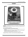
The motor control unit is supplied as a module in a simple plastic housing. You should
therefore choose an installation site with the following conditions:
The ambient temperature may not be lower than -20°C and not higher than
+50°C.
The air humidity must lie within 30...90% RH.
Electromagnetic fields at the installation site must be reliably shielded.
Preferably protected against direct sunlight and driving rain
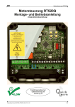
b) Installation
The internal temperature rating is designed for vertical installation.
[X1], [X5] show the installation, whereby the cables must be brought out at the bottom
and sealed with the enclosed threaded joints to prevent penetrating moisture.
When choosing the type of fixing, you must take into account the weight of the control
unit (see technical specifications).
Properly fit the control unit housing in the suitable installation site.
3) Brief Explanation of Terms Used
You will come across the following terms in these instructions, not in everyday use:
Release / release time
In various safety functions you can choose how the gate is to behave in a given
situation. In the event of “release” the gate only moves for the set release time in
“opposite direction”, in order to release the obstruction.
Active leaf
In 2-leaf gate systems, one leaf can be chosen as the “active leaf”. This can then be
opened separately (e.g. as a doorway for people).
OSE
Self-monitoring Optical Safety Equipment as photoelectric barrier or as contact
strip.
Panic function
In the panic function an open/close command during a gate travel always results in the
stopping of the gate travel. The gate only starts to move in the required direction if
actuated again.
Reversing
If various safety functions you can choose how the gate is to behave in a given
situation. In “reversing” the gate moves in the opposite direction to the end position.
Smooth travel-out
5 / 35
Motor control unit DCM31
The motor output / motor speed can be reduced over the last part of the travel path so
that the gate does not hit the end stop at full speed.
Electricity stop
The control unit monitors the motor current for obstacle detection. You can choose
how the control unit reacts if the set value is exceeded.
Partial opening
The gate can be specifically moved to a previously selected position between the limit
switches (e.g. to allow people through).
a) Abbreviations used in the instructions
[Bl.1]
[Bl.2]
[J1]
[Kl.1]..[Kl.33]
M1, M2
[M.A0]..[M.A9]
[M.b0]..[M.b9]
[M.C0]..[M.C9]
[M.d0]..[M.d9]
[Ta.+]
[Ta.-]
[Ta.F]
[Ta.M]
[X1]..[X10]
{F0}..{F9}
{Er.00}..{Er.29}
6 / 35
= 15 pin slot for the radio module
= 2x10 pin slot for 1 or 4 channel radio receiver
= Jumper for safety equipment (SE)
= Reference to terminals
= Motor 1 or Motor 2
= Menu items A0 to d9
= “+” pushbutton in the control panel under the 7 segment display
= “-” pushbutton in the control panel under the 7 segment display
= “Radio” pushbutton in the control panel under the 7 segment display
= “Menu” pushbutton in the control panel under the 7 segment display
= Reference to figure in the separate graphic overview
= Radio module function, shown in the display
= Error/fault message, shown in the display
Motor control unit DCM31
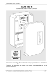
4) Connections
a) Terminals
[X2], [X6]
Only work on the controls after it has been disconnected from the power
supply and has been ESD-compatibly earthed!
-
-
-
230 volt mains voltage can be applied to [Kl.1]..[Kl.4] and [Kl.30], [Kl.31]. Potentially
fatal danger!
Never connect mains voltage to [Kl.5].. [Kl.29].
Failure to comply causes immediate destruction of the controls and the guarantee
expires!
Signal and motor cables (e.g. pulse, open, stop, close...) must not exceed a length
of max 30 m! This does not apply to the mains supply cable.
[Kl.1]+[Kl.2] mains voltage 230V / AC
Terminal 1 = N conductor
Terminal 2 = L conductor
Comply with the local safety regulations and applicable VDE regulations.
We recommend installation of a motor protecting switch in the mains supply cable.
[Kl.3]+[Kl.4] light / warning light 230 V / AC output, max. 500W
Terminal 3 = N conductor
Terminal 4 = L conductor (L= connected)
The light/warning light function is set via [M.b2].
The switched status is displayed by the yellow “Light” LED [X7].
[Kl.5]+[Kl.6] Motor M1, 24V / DC output
Terminal 5 = “-“ for opening
Terminal 6 = “+“ for opening
Motor 1 is the main motor and is also used as the active leaf motor.
If the control unit is run with one motor only [M.C1], this must be connected to M1.
In 2 motor mode, for opening motor 1 starts at the same time or before motor 2
[M.C3] and for closing motor 1 starts at the same time or after motor 2 [M.C2].
After the control unit has been installed and the first pulse command is given, the
direction of travel must be “OPEN”.
If the drive unit, despite bar running upwards in the 7 segment display, starts up in
the “CLOSE” direction the connection wires [Kl.5]+[Kl.6] must be switched over.
The control unit learns the maximum motor current for each direction of travel.
Motor adjustments are made in [M.A1]..[M.A8].
[Kl.7]+[Kl.8] Motor M2, 24V / DC output
Terminal 7 = “-“ for opening
Terminal 8 = “+“for opening
After the control unit has been installed and the first pulse command is given the
direction of travel must be “OPEN”.
If the control unit is operated with one motor only [M.C1], it must be connected to
M1.
In 2 motor mode motor 2 starts in opening at the same time or after motor 1 [M.C3]
and in closing motor 2 closes at the same time or before motor 2 [M.C2].
7 / 35
Motor control unit DCM31
-
-
If the drive unit, despite the bar moving upwards in the 7 segment display, start up
in the “CLOSE” direction, the connection wires [Kl.7]+[Kl.8] must be switched over.
The control unit learns the maximum motor current for each direction of travel.
Motor adjustments are made in [M.A2]..[M.b0].
[Kl.9]+[Kl.10] output 12 V DC / stable
Terminal 9 = 12 V/DC stable, max. 40 mA
Terminal 10 = 0 V/earth
e.g. for OSE connection
[Kl.10]+[Kl.11] output 24 V / DC unstable
Terminal 11 = 24 V/DC unstable, max. 200 mA
Terminal 10 = 0 V/earth
e.g. for connecting the supply voltage for a photoelectric barrier
[Kl.12]+[Kl.13] relay output (floating)
For connecting electric lock or other options, max. 24 Volt, 4 ampere.
The function is set via [M.C4].
The switched status is displayed via the yellow “OUT“ LED [X7].
-
[Kl.14]+[Kl.15] emergency stop
Controls with floating contact can be connected to the emergency stop input.
The behaviour of the control unit following an emergency stop is set via [M.b8].
The contact must be closed in the idle condition (break contact).
Several controls can be connected in series.
An unused emergency stop input must be jumpered!
The switched status of the emergency stop input is displayed by the red LED
behind the [Kl.14]+[Kl.15].
The emergency stop input directly switches off the motor relay for safety reasons
and therefore is still active even if the electronics fail!
In the event of an emergency stop command the motor stops immediately.
If the emergency stop command while the motor is running, with the next pulse
command the gate travels in the “opposite direction” (away from the danger spot).
If an emergency stop command is given while the gate is at a standstill, the gate
generally travels in the OPEN direction when the next pulse command is given.
[Kl.16]+[Kl.17]+[Kl.18] limit switch M1
Terminal 16 + 17 = limit switch M1 OPEN
Terminal 18 + 17 = limit switch M1 CLOSE
[Kl.19]+[Kl.20]+[Kl.21] limit switch M2
Terminal 19 + 20 = limit switch M2 OPEN
Terminal 21 + 20 = limit switch M2 CLOSE
Controls with floating contact (break contact) can be connected at the limit switch
inputs.
The contact must be closed in the idle condition (opened in the end position).
The switched status is displayed via the LEDs behind the terminals. (LEDs lit in
end position, i.e. if limit switch pressed/opened)
If [M.C6] = 00 or = 02, the limit switch inputs function and the LEDs are always off.
Alternatively, drive units with integrated limit switches can be used [M.C6], which
interrupt the motor current in the relevant direction. The control unit then interprets
8 / 35
Motor control unit DCM31
this as an external limit switch. The limit switch behind the terminals is not
displayed.
[Kl.22]+[Kl.23] photoelectric barrier (LS)
Terminal 22 = LS signal input
Terminal 23 = connected earth
A photoelectric barrier or an electrical safety contact strip with a floating breakcontact element can be connected.
The function of the input is determined via [M.b4].
If the input is not used, it must be jumpered with a wire jumper (delivered
condition).
The switched status is displayed by the yellow LED behind [Kl.22]+[Kl.23].
During the control unit self-test, the LED briefly flashes.
The input has a safety function and is monitored by self-tests of the electronics.
The “close after leaving the photoelectric barrier” function [M.b5] can be triggered
via the photoelectric barrier input.
[Kl.23]+[Kl.24] safety input (SE) for closing edge safety device 8K2 or OSE
Terminal 23 = connected earth
Terminal 24 = SE signal input
Optional use of a 8K2 safety strip or OSE is possible as a closing edge safety
device.
The type of strip connected and function of the input are set via [M.b6].
OSE connection: Kl.9=+12V, Kl.10=earth, Kl.24=signal
The switched status is displayed via the yellow LED behind [Kl.24].
If the SE input is not used, the [J1] must be connected to NC [X4] (8k2-resistor is
switched on internally) and [M.B6] set to 8k2 (10) or the SE input deactivated
[M.B6] = 00.
If a closing edge safety device is connected, [J1] must be connected to SE [X4].
This input has a safety function and is monitored by self-tests of the electronics.
[Kl.25]+[Kl.26] input A (pulse / open)
Input for pushbutton, key-operated switch, external radio, etc.
The controls must have a floating contact, which is open in the idle condition (make
contact).
Several pushbuttons, etc. can be connected in parallel.
The input is connected internally parallel to the slot of the radio receiver ([Bl.2]
channel 1).
The switched status is displayed by the green LED behind [KL.25]+[Kl.26].
The function of the input is set via [M.b9].
Simultaneous actuation of input A and input B has an emergency stop function.
[Kl.26]+[Kl.27] input B (partial opening/ active leaf / close)
Input for pushbuttons, key-operated switch, external radio, etc.
The controls must have a floating contact, which is open in the idle condition (make
contact).
Several pushbuttons, etc. can be connected in parallel.
The input is connected internally parallel to the slot of the radio receiver ([Bl.2]
channel 2).
The switched status is displayed via the green LED behind [Kl.26]+[Kl.27].
The function of the input is set via [M.b9].
9 / 35
Motor control unit DCM31
-
Simultaneous actuation of input A and input B has an emergency stop function.
[Kl.28]+[Kl.29] antenna
An antenna litz wire must be connected to [Kl.29] and must be stretched parallel to
the main reception direction along its whole length.
The antenna litz wire can be fed out through the small hole next to the self-sealing
plugs.
The largest range is achieved by laying the cable at a large distance from the metal
parts (concrete ceilings, cables, ...).
If a rod antenna is used, the shielding of the coax cable is connected to the
adjacent earth terminal [Kl.28].
[Kl.30]+[Kl.31] transformer connection (primary 230V/AC)
[Kl.32]+[Kl.33] transformer connection (secondary 24V/AC)
An external power transformer (usually installed in the factory) must be connected
to [Kl.30] and [Kl.31] (primary) and [Kl.32] and [Kl.33] (secondary).
For safety and EMC reasons, a short-circuit proof toroidal transformer to EN60742
(VDE0551) must be used.
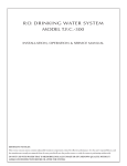
b) Radio
[X8], [X10]
The control unit can be remotely controlled, either via the radio module (evaluation
and storage of the radio code in the controller of the control unit) or via a radio
receiver with integrated logic for evaluation and storage of the radio code. The
radio receiver and radio module work independent of each other.
Radio module mode [Bl.1]
A suitable radio module must be plugged with correct orientation into the 15-pin
socket connector [Bl.1] [X9] [X8].
Replace radio module: (frequency change): If noise exists in the frequency band
used, the control unit can be converted to another frequency by replacing the radio
modules.
Procedure:
• Switch off power supply!
• Carefully pull the radio module out of the plug-in holder.
• Plug-in the new radio module with the required frequency with the “correct
orientation”.
• Switch supply voltage back on.
• Delete radio (see p 20).
• Teach new sender (see p 20).
• The transmitters must have the same frequency as the new radio module!
Radio receiver [Bl.2]
A suitable radio receiver must be plugged in, with the correct orientation, in the
2x10-pin socket connector [Bl.2] [X9] [X10].
Channel 1 is internally connected parallel to input A.
Channel 2 is internally connected parallel to input B.
The function of channels 1 and 2 is set via [M.b9].
Refer to the respective operating instructions for information on how to use the
radio receiver.
-
10 / 35
Motor control unit DCM31
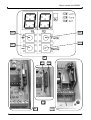
5) Controls / Displays
[X7]
[Ta.+]
[Ta.-]
[Ta.F]
[Ta.M]
+: value + / menu + / open function
-: value - / menu - / close function
Radio: key to teach / delete the radio in radio module mode
Menu: menu selection/ display input status
a) LEDs next to the display
[X7]
Light (yellow)Light / warning light control display
radio (red) radio display for radio module mode (reception)
OUT (yellow) display output OUT [Kl.12]+[Kl.13]
b) LEDs behind terminals
[X6]
behind [KL.14]+[Kl.15]
red
behind [KL.16]+[Kl.17]
behind [KL.17]+[Kl.18]
green limit switch M1 OPEN
green limit switch M1 CLOSE
behind [KL.19]+[Kl.20]
behind [KL.20]+[Kl.21]
green limit switch M2 OPEN
green limit switch M2 CLOSE
behind [KL.22]+[Kl.23]
behind [KL.23]+[Kl.24]
yellow photoelectric barrier (LS)
yellow closing edge safety device (SE)
behind [KL.25]+[Kl.26]
behind [KL.26]+[Kl.27]
green input A
green input B
emergency stop input
c) Jumper [J1]
[X4]
If a closing edge safety device is connected to the SE input (8K2 or OSE), the
jumper must be connected to SE.
If no closing edge safety device is connected, the jumper must be connected to
NC.
11 / 35
Motor control unit DCM31
d) 2 x 7-Segment: Display menus and states
Gate status (horizontal bar)
[X7]
Segment
A
B
C
D
E
F
Left
Left
Left
Segment status
Lit
Lit
Lit
Lit
Lit
Lit
Bars moving upwards
Bars moving downwards
Bar stopped + flashing
Motor
1
1
1
2
2
2
1
1
1
Right
Right
Right
Bars moving upwards
Bars moving downwards
Bar stopped + flashing
2
2
2
Left point
(0)
Right
points (0)
Lit
1+2
Flashing
1+2
Gate status
Standing in CLOSE end position
Standing between end positions
Standing in OPEN end position
Standing in CLOSE end position
Standing between end positions
Standing in OPEN end position
Opening
Closing
Last travel was ended with SE, LS
or forced stopping (obstruction!)
Opening
Shutting
Last travel was ended with SE, LS
or forced stopping (obstruction!)
Automatic closing is active, keep
open time running
Automatic closing is active, early
warning running
Input status (vertical bar)
[X7]
Segment
1
2
3
4
5
6
7
8
9
0
0
Segment status
lit
lit
lit
lit
lit
lit
lit
lit
lit
lit
flashing
Input
limit switch M1 OPEN actuated = open
limit switch M1 CLOSE actuated = open
input LS pressed = open
input SE pressed = open or short-circuited
input A actuated = closed
input B actuated = closed
limit switch M2 OPEN actuated = open
limit switch M2 CLOSE actuated = open
emergency stop actuated = open
Automatic closing is active, keep open time running
Automatic closing is active, early warning running
Learning runs:
Brief display of the digits 1..4 = number of learning runs still to be performed
separately for M1 (left display) and M2 (right display).
Radio:
During teaching for radio module mode the display switches between gate status
and {F0}..{F9} for the selected radio function. In addition, the “radio” LED next to
the 7-segment display flashes.
Deletion of all codes in radio module mode is indicated by rapid flashing of {FL} in
the display and by rapid flashing of the “radio” LED.
If a teaching radio is detected, the teaching function {F0}..{F9} is shown in the
display and the “radio” LED is lit.
Error messages:
Display switches between “ER” (error) and error number.
12 / 35
Motor control unit DCM31
Menu settings:
The menu item (A0...d9, prefixed letter) or the set menu value (00...99) is displayed.
e) Function of the keys
[X7]
“Menu” key [Ta.M]
[Ta.M] < 1sec actuated in function mode = switch the display between
gate status (horizontal bar)
and / input status (vertical bar).
“+” key [Ta.+]:
in gate status mode and input status: opening or stop.
in setting mode: see 6)a) Using menu function, p. 14
-
“-“ key [Ta.-]:
in gate status mode and input status: closing or stop
in Adjustment mode: see 6)a) Using menu function, p 14
13 / 35
Motor control unit DCM31
6) Putting into Service / Programming
a) Using menu function
The buttons [Ta.+], [Ta.-] and [Ta.M] next to the display [X7] can be used to
set/change the individual functions of the control unit as follows:
[Ta.M] > pressed for 1 sec = Switch between display
function (display: horizontal or vertical bar)
and setting (display: letters/digits).
[Ta.M] < pressed for 1 sec in function mode = switch between display
gate status (horizontal bar)
and / input status (vertical bar).
[Ta.M] < pressed for 1 sec in setting mode = switch between displays
Menu item (left display letter A, b, C, d)
and menu value (both displays with digits, 00-99)
-
-
-
Use [Ta.+] and [Ta.-] to select the menu item to be changed [A0..d9].
Use [Ta.M] < 1 s to select “Menu value” mode (display 00...99, digits only).
Use [Ta.+] and [Ta.-] to set the required value.
Press button < 1 s to reselect “Menu item” mode
Adjust all settings using this schema.
If the menu value is changed, this value is automatically adopted and saved.
If none of the buttons are pressed for longer than 15 sec, the display switches back
to gate status.
During the setting mode it is not possible for the motor to run.
b) Gate type default setting
After all the additional equipment (SE, LS, ES...) and loads (motor, warning light, ...)
have been connected, the gate type must be set first!
The gate type can be preset using [M.A0].
By changing [M.A0], all menu items are preset to the typical values for this type of
gate (factory setting) and the force values and running times are deleted, so that
new teaching runs must be carried out!
Changing [M.A0] via [Ta.+] and [Ta.-] is only possible by simultaneously actuating
[Ta.F], to prevent accidental adjustment!
c) Programming
Use the table from page 16 to set the required parameters for the individual menu
items, and enter the selected values in the “Setting” column.
d) Deleting the force values and travel paths
-
-
- Press [Ta.-] and [Ta.+] simultaneously until “44” flashes in the display. During the
deletion the two points in the display flash rapidly.
- Important: New teaching runs must be completed (see below).
e) Teaching runs / learn force values
-
If all menu items have been set, 4 complete teaching runs from limit switch to limit
switch must be completed to learn the force values and travel paths (for operation
without limit switch [M.C6] = 02 only 2 teaching runs).
14 / 35
Motor control unit DCM31
-
-
During the teaching runs no STOP along the path is allowed! The gate must be
able to travel unobstructed from limit switch to limit switch.
The flashing digits in the display indicate how many teaching runs still have to be
completed for which motor.
Command
1 x pulse or “OPEN”
1 x pulse or “CLOSE”
“CLOSE”
1 x pulse or “OPEN”
1 x pulse or “CLOSE”
“CLOSE”
-
Status/function
Gate is closed:
Both leafs are moving “OPEN”
Motor 2 moving “CLOSE”, then motor 1 moves
Both gate leafs are moving “OPEN”
Motor-2 moves "CLOSE”, motor 1 moves with delayed
The teaching runs are completed when the digits no longer flash.
Check the forced stopping / obstruction detection and all connected safety devices
for compliance with EN12445 and EN12453!
f) Reset the control unit (factory setting)
-
-
-
The control unit can be reset by adjusting [M.A0] and then resetting to the “Original
value”.
Procedure:
• [Ta.M] pressed until [M.A0]..[M.d9] appears.
• Use [Ta.-] to select menu item [M.A0].
• Briefly press [Ta.M], menu value (00...07) is displayed.
• Press [Ta.F] and simultaneously use [Ta.+] and [Ta.-] to adjust the menu value
and then reset again.
• Release [Ta.F].
• All menu settings are reset to their basic values (factory setting) for the relevant
gate type of [M.A0].
Important: When the control unit is reset, the functions of the safety equipment are
changes. It is necessary to reset the whole control unit and to complete new
teaching runs.
15 / 35
Motor control unit DCM31
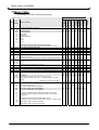
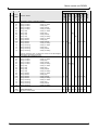
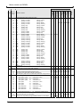
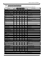
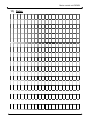
7) Menu Table
Grey background: basic values (factory setting)
Basic values
00..20
00..20
00..20
00..20
00
01..20
A6
00..05
00..30
00..30
00..30
00..30
00
01..62
63..90
b2
2-leaf hinged gate
1-leaf hinged gate
Sliding gate
Folding gate
Roller shutter gate
Type 5
Type 6
Type 7
(Important: Changing effects all other menu items)
Switch over only possible by simultaneously pressing the radio key
Motor voltage Smooth travel-out M1
Motor voltage Smooth travel-out M2
Motor voltage along path M1
Motor voltage along path M2
Length smooth travel motor1 and motor2
No smooth travel-out
Travel time in 0.5 sec steps before end position, start point self-teaching
START-UP TIME after motor start (start time, electric lock, electricity
fade-out)
Start up time in 0.5 sec steps, 0.5..3.0 sec
Force in open M1 (electricity stop)
Force in close M1 (electricity stop)
Force in Open M2 (electricity stop)
Force in close M2 (electricity stop)
AUTOMATIC CLOSING
switched off
keep open time in 2sec steps, plus 5sec early warning
keep open time 63=3min, 64=4min, ... , 90=30min plus 5 sec early
warning
(Number – 60 = time in minutes)
LIGHT / WARNING LIGHT function
00
01
02
03
Only while motor running
1min overrun travel after motor operation
2min overrun travel after motor operation
3min overrun travel after motor operation
04
05
4sec before motor start open and close and while motor running
4sec before motor start open and close and while motor running flashing (1Hz)
06
07
08
09
16 / 35
4sec before motor start close and while motor running
4sec before motor start close and while motor running - flashing (1Hz)
Status display: gate in OPEN end position
Status display: gate in CLOSE end position
00
00
00
00
00
00
00
00
10
10
20
20
10
10
20
20
10
10
20
20
5
5
20
20
10
10
20
20
10
10
20
20
10
10
20
20
10
10
20
20
05
05
05
05
05
05
05
05
02
02
02
02
02
02
02
02
15
15
15
15
15
15
15
15
15
15
15
15
15
15
15
15
15
15
15
15
15
15
15
15
15
15
15
15
15
15
15
15
00
00
00
00
00
00
00
00
02
02
02
02
00
02
02
02
Setting
[M.A0] = 07
Type 7
[M.A0] = 06
Type 6
[M.A0] = 05
Type 5
[M.A0] = 04
Roller
shutter gate
[M.A0] = 03
Folding gate
[M.A0] = 02
Sliding gate
[M.A0] = 01
00
01
02
03
04
05
06
07
A7
A8
A9
b0
b1
[M.A0] = 00
DEFAULT SETTING for gate type
A0
A1
A2
A3
A4
A5
Function / values
1-leaf.-Hinged
gate
Value
range
2-leaf.-Hinged
gate
Menu
Motor control unit DCM31
Basic values
Setting
[M.A0] = 07
Type 7
[M.A0] = 06
Type 6
[M.A0] = 05
Type 5
[M.A0] = 04
Roller
shutter gate
[M.A0] = 03
Folding gate
[M.A0] = 02
Sliding gate
[M.A0] = 01
[M.A0] = 00
Function / values
1-leaf.-Hinged
gate
Value
range
2-leaf.-Hinged
gate
Menu
ELECTRICITY STOP / obstruction detection
b3
00
01
02
03
opening: no effect
opening: no effect
opening: no effect
opening: no effect
closing: no effect
closing: stop
closing: release
closing: reversing
04
05
06
07
opening: stop
opening: stop
opening: stop
opening: stop
closing: no effect
closing: stop
closing: release
closing: reversing
08
09
10
11
opening: release
opening: release
opening: release
opening: release
closing: no effect
closing: stop
closing: release
closing: reversing
12
13
14
15
opening: reversing
opening: reversing
opening: reversing
opening: reversing
closing: no effect
closing: stop
closing: release
closing: reversing
05
07
10
10
10
10
10
10
10
10
10
00
00
00
00
11
Important: If electricity stop “no effect” the control unit can be damaged
or destroyed in the event of overload!
PHOTOELECTRIC BARRIER function
b4
00
01
02
03
opening: no effect
opening: no effect
opening: no effect
opening: no effect
closing: no effect
closing: stop
closing: release
closing: reversing
04
05
06
07
opening: stop
opening: stop
opening: stop
opening: stop
closing: no effect
closing: stop
closing: release
closing: reversing
08
09
10
11
opening: release
opening: release
opening: release
opening: release
closing: no effect
closing: stop
closing: release
closing: reversing
12
13
14
15
opening: reversing
closing: no effect
opening: reversing
closing: stop
opening: reversing
closing: release
opening: reversing
closing: reversing
Close after leaving the photoelectric barrier
b5
00
01..20
Function switched off
Delay time in 0.5sec steps
03
10
10
00
00
00
03
00
17 / 35
Motor control unit DCM31
Basic values
CLOSING EDGE SAFETY DEVICE function
b6
00
01
02
03
8k2
8k2
8k2
8k2
opening: no effect
opening: no effect
opening: no effect
opening: no effect
closing: no effect
closing: stop
closing: release
closing: reversing
04
05
06
07
8k2
8k2
8k2
8k2
opening: stop
opening: stop
opening: stop
opening: stop
closing: no effect
closing: stop
closing: release
closing: reversing
08
09
10
11
8k2
8k2
8k2
8k2
opening: release
opening: release
opening: release
opening: release
closing: no effect
closing: stop
closing: release
closing: reversing
12
13
14
15
8k2
8k2
8k2
8k2
opening: reversing
opening: reversing
opening: reversing
opening: reversing
closing: no effect
closing: stop
closing: release
closing: reversing
16
17
18
19
OSE
OSE
OSE
OSE
opening: no effect
opening: no effect
opening: no effect
opening: no effect
closing: no effect
closing: stop
closing: release
closing: reversing
20
21
22
23
OSE
OSE
OSE
OSE
opening: stop
opening: stop
opening: stop
opening: stop
closing: no effect
closing: stop
closing: release
closing: reversing
24
25
26
27
OSE
OSE
OSE
OSE
opening: release
opening: release
opening: release
opening: release
closing: no effect
closing: stop
closing: release
closing: reversing
28
29
30
31
OSE
opening: reversing
OSE
opening: reversing
OSE
opening: reversing
OSE
opening: reversing
Release time
02
02
02
02
02
10
10
10
Release time in 0.25 sec steps, 0.25..4.00 sec
EMERGENCY STOP input function
07
07
01
07
07
07
07
07
00
01
02
Automatic closing blocked after emergency stop
Closing time runs again after emergency stop release
After emergency stop next run in start travel, automatic closing blocked
Function of inputs A/B and radio receiver
00
00
00
00
00
00
00
00
00
01
02
A:
A:
A:
Open pulse + panic
Open pulse + panic
Open pulse + panic
B:
B:
B:
Close pulse + panic
Close pulse
Close dead man
00
00
00
00
00
00
00
00
03
04
05
A:
A:
A:
Open pulse
Open pulse
Open pulse
B:
B:
B:
Close pulse + panic
Close pulse
Close dead man
06
07
08
A:
A:
A:
Open dead man
Open dead man
Open dead man
B:
B:
B:
Close pulse + panic
Close pulse
Close dead man
09
A: Pulse (open-stop-close-...)
B:
Duration of the PARTIAL OPENING
00
00
00
10
10
b7
00..15
b8
b9
C0
00
01..99
18 / 35
closing: no effect
closing: stop
closing: release
closing: reversing
Active leaf / partial opening
Active leaf mode (only in 2-leaf mode)
Running time until partial opening/ventilation position in 0.5 sec steps
00
00
02
Setting
[M.A0] = 07
Type 7
[M.A0] = 06
Type 6
[M.A0] = 05
Type 5
[M.A0] = 04
Roller
shutter gate
[M.A0] = 03
Folding gate
[M.A0] = 02
Sliding gate
[M.A0] = 01
[M.A0] = 00
Function / values
1-leaf.-Hinged
gate
Value
range
2-leaf.-Hinged
gate
Menu
Motor control unit DCM31
Basic values
Setting
[M.A0] = 07
Type 7
[M.A0] = 06
Type 6
[M.A0] = 05
Type 5
[M.A0] = 04
Roller
shutter gate
[M.A0] = 03
Folding gate
[M.A0] = 02
Sliding gate
[M.A0] = 01
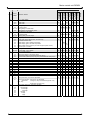
1- / 2- LEAF MODE
00
01
C2
2- leaf mode
1- leaf mode
Closing delay in 2-leaf mode
00
01..19
20
No closing delay
Closing delay in 0.5sec steps
Closing delay is automatically learnt
Open delay in 2-leaf mode
00
01..19
No opening delay
Opening delay in 0.5sec steps
Relay output OUT function
C3
C4
00
01
02
03
04
05
C5
00..99
C6
C7
C8
C9
d0
d1
d2
d3
d4
d5
d6
d7
d8
[M.A0] = 00
C1
Function / values
1-leaf.-Hinged
gate
Value
range
2-leaf.-Hinged
gate
Menu
01
00
00
00
00
99
99
99
01
01
01
control panel free, menu items adjustable
control panel blocked, menu items not adjustable
Switchover:
emergency stop, Simultaneously press + key
and – key ,
Switchover with menu key
Trip counter (read only, cannot be changed)
00
00
03
20
20
20
04
04
04
00
00
00
00
99
99
99
99
01
01
01
01
00
00
00
00
00
03
00
04
in 1 sec steps, 1 sec..100sec
Type of LIMIT SWITCH
00
01
00
01
20
00
Internal limit switch (in the motor cable)
External limit switch (connected to terminals 16-21)
No limit switch (electricity stop only) only permissible with safety strips!
Service mode
00
01
02
03
04
05
00
01
Electric lock (during startup time, see menu A6)
Photoelectric barrier test
Status display: gate in OPEN end position
Status display: gate in CLOSE end position
Radio module function 8 and 9 (if current surge drop after 10min)
Forward Open command
Running time limit
00
01
02
00
00
00
00
00
00
00
00
00
00
00
d9
00
00
02
03
15
02
00
00
00
00
100,000 digit
10,000 digit
1,000 digit
100 digit
10 digit
1 digit
19 / 35
Motor control unit DCM31
8) Functional Description
a) Radio module
-
-
-
-
-
The radio frequency and modulation type is determined by the plug-in radio module
in [Bl.1].
The transmitter coding is teaching. Up to 40 codes (transmit keys) can be teaching
with different functions.
The motor control unit can either learn the 12 bit dual coding schema, the 18 bit
tristate coding schema or Keeloq coding. Further coding types by arrangement.
The type of coding schema is specified during teaching of the first transmitter –
after deleting all codes. The first learning process can take up to 10s!
If an already teaching transmitter is re-teaching, the control unit recognises this and
does not allocate any more of the 40 memory locations.
Teaching a transmitter:
• Briefly press [Ta.F] once. Radio LED flashes.
• The 7 segment display shows which function is being learnt.
• Press [Ta.F] until the required function is displayed (F0..F9).
• Press the transmit key to be teaching until the “Radio” LED is permanently lit.
The transmitter has now been teaching.
• If a transmitter is not teaching, learn mode is automatically quit after 15 s.
Functions for operation with radio module
• {F0} Pulse (open-stop-close-..) (not for dead man)
• {F1} Open pulse with panic function, i.e. stop while motor running
• {F2} Close pulse with panic function, i.e. stop while motor running
• {F3} Stop
• {F4} Partial opening / active leaf *
• {F5} Light
• {F6} Open pulse (without panic function)
• {F7} Close pulse (without panic function)
• {F8} OUT relay (active if [M.C4] = 04) pulse function
• {F9} OUT relay (active if [M.C4] = 04) current surge function
* Note: If dead man function is set via [M.b9], the relevant direction of travel cannot be
controlled by radio!
Delete all transmitters:
• Keep [Ta.F] pressed for approx 6 s.
• Radio LED flashes fast and in {FL} flashes in the display.
• If the flashing stops, all coding is deleted.
b) Input A and B and radio receiver
-
-
-
The inputs A and B and channels 1 and 2 of the radio receiver slot are connected
in parallel.
The function of the inputs A, B [Kl.25]+[Kl.26]+[Kl.27] and the radio receiver in
[Bl.2] can be selected via [M.b9] between open, close, pulse and partial opening.
If dead man’s mode is set, radio mode via the radio module is blocked for the
relevant direction of travel. Operation with radio receiver in [Bl.2] is not permitted in
this direction of travel.
20 / 35
Motor control unit DCM31
-
-
-
If the panic function is set in [M.b9] for input A or B, actuating the corresponding
input during gate travel always causes the gate travel to stop. Only a further
actuation restarts the gate in the required direction of travel.
If no panic function is set, actuation during gate travel causes stop in opposite
direction and immediate start in opposite direction, the actuation has no effect in
the same direction.
Simultaneous actuation of input A and input B effects the emergency stop function.
c) Automatic closing
-
-
-
-
-
-
-
-
-
-
-
Automatic closing is activated or adjusted via [M.b1].
If [M.b1] = 00, automatic closing is inactive
The values 01..62 correspond to a keep open time in 2sec steps.
From the value 63..90 the keep open time is counted in minute steps (i.e. value –
60 = time in minutes)
If the gate is not in the CLOSE end position, after the keep open time [M.b1] has
expired an early warning is issued for 5 s via the light output, before the gate
moves into CLOSE end position.
While the keep open time is running, the point in the right display is lit. During the
early warning the point in the right display flashes.
If automatic closing is activated a pulse command always causes travel to OPEN
end position.
If the gate is in OPEN end position, a pulse command only resets the keep open
time.
As long as a pulse or open command is applied, the keep open time remains reset.
Only after there is no open/pulse command applied or queued does the keep open
time begin to count (suitable for time switch control unit).
Commands for specific open/close are active even if automatic closing is active.
Closing is stopped and the keep open time is reset via the LS input.
If, during closing, the gate is stopped by forced stopping, the automatic closing is
blocked until the next pulse, open, close, TÖ or radio command.
If the unit is switched off twice consecutively via SE while closing, automatic
closing is blocked after the second unsuccessful closing until the next pulse, open,
closed, TÖ or radio command.
If [M.b8] = 00, after actuating the emergency stop, automatic closing is blocked
until the next pulse, open, close, TÖ or radio command.
If the motor is at a standstill only resetting of the keep open time (no switching off)
occurs in SE. Only after the input is no longer actuated does the keep open time
begin to count.
If automatic closing is activated it is always active one of the gate leafs is not in the
CLOSE limit switch. I.e. automatic closing takes place even in partial opening and
active leaf mode.
d) Partial opening (TÖ)
-
-
-
Partial opening can be controlled via input B, the second channel of a radio
receiver in [Bl.2] or via function (F4) in radio module mode.
The partial opening time is set via [M.C0].
The running time is a reference for the part open position. Therefore, slight
deviations in the opening position can occur.
A partial opening command when the gate is in CLOSE end position always
causes travel to the part open position.
21 / 35
Motor control unit DCM31
-
-
-
-
If the gate is outside the CLOSE end position, if a partial opening command is
issued the gate moves to the CLOSE end position.
Even if automatic closing is activated, the gate can be moved by a partial opening
command in the part open position. After the closing time has expired the gates
automatically close.
A pulse command while the gate is in the part open position causes it to travel to
the OPEN end position.
If a part open position is set via [M.C0], active leaf mode is not possible.
e) Active leaf (GF)
-
-
-
Active leaf mode (only in 2-leaf mode) can be controlled using the open-stop-closestop function, for motor 1 only, via input B, the second channel of a radio receiver in
[Bl.2] or via function (F4) in radio module mode.
Active leaf mode is only possible if the partial opening time is set in [M.C0] = 00.
An active leaf command is only active if motor 2 is in CLOSE end position.
Even if automatic closing is active, the gate can still be controlled via an active leaf
command. After the closing time has expired the gate automatically closes.
A pulse command after an (effective) active leaf command always causes travel to
open.
f) Closing delay: (in 2-motor mode)
-
-
-
The closing delay between motor 1 and motor 2 can be set via [M.C2].
If [M.C2] = 00 (no closing delay), both motors always simultaneously start in the
CLOSE direction.
If [M.C2] = 20 (closing delay automatically learnt) the runtimes of both motors are
determined during the teaching runs and the closing delay is determined so that
motor 1 reaches the CLOSE end position approx 3-4 sec after motor 2.
The closing delay [M.C2] must be set so that so the closing edge never moves at a
flat horizontal angle toward the opposite leaf, which could cause damage to the
gate system and hazards for objects and people!
g) Opening delay: (in 2 motor mode)
-
-
The opening delay between motor 1 and motor 2 can be set via [M.C3].
If [M.C3] = 00 (no opening delay), both motors always start simultaneously in the
OPEN direction.
The opening delay [M.C3] must be set so motor 2 is not obstructed by motor 1
during opening (contact by closing edge).
h) Smooth start
-
When the motor starts the gate is slowly accelerated to the final speed.
The duration of this start time, during which the gate leafs are accelerated,
depends on the startup time after motor start [M.A6]. The larger the value, the
slower the gate is accelerated.
i) Smooth travel-out length and motor voltage
-
-
Before the gate has reached the end position, the voltage is reduced causing the
gate to slowly move into the end position.
The travel-out voltage can be separately set for motor 1 and motor 2 via [M.A1] and
[M.A2]. The smaller the value, the slower the gate moves (minimum speed = 00,
maximum speed = 20).
22 / 35
Motor control unit DCM31
-
-
-
The settings for the length of the travel-out are entered via [M.A5]. The larger the
value the longer the smooth travel before the end position. During the teaching
rungs the starting point of smooth travel is determined separately for each direction
of travel and motor.
Each time changes are made to [M.A1], [M.A2] and [M.A5], the force values and
travel paths are deleted and new teaching runs must be completed.
The motor voltage affects the force values for forced stopping. After the motor
voltage has been changed the closing forces must be checked and if necessary
corrected via [M.A7]..[M.b0].
j) Motor voltage over travel path
-
-
-
[M.A3] and [M.A4] can be used to separately set the voltage over the travel path for
motor 1 and motor 2. The smaller the value, the slower the gate moves (minimum
speed = 00, maximum speed = 20).
The motor voltage influences the force values for forced stopping. If the motor
voltage is changed the closing forces must be checked and if necessary corrected
via [M.A7]..[M.b0].
Each time a change is made to [M.A3] and [M.A4], the force values and travel
paths are automatically deleted and new teaching runs must be completed.
k) Smooth stop
-
-
A stop command along the travel path causes slow coasting of the motor. It is not
stopped abruptly. (exception: forced stopping, SE, LS, emergency stop).
There is no smooth stop in dead man's mode.
l) Light / warning light
-
-
-
[M.b2] is used to set the function of the light/ warning light output.
If a warning light is connected to the light output, the menu values 00 (for motor
running) and 04-07 (engine running+early warning) are provided. If 04 and 05 an
early warning of 4sec is given before engine running in OPEN and CLOSEdirection and if 06 and 07 only before engine running in CLOSE direction.
Menu values 04 and 06 are intended for a self-flashing warning light, in 05 and 07
the flashing is generated by the light relay.
If [M.b2] = 08 or 09 the light relay switches if the gate is in OPEN or CLOSE end
position (M1+M2, in 1-leaf gate M1 only).
m) Emergency stop
-
-
-
-
-
-
The emergency stop input directly switches off the motor relay for safety reasons
and is therefore is still active even if the electronics fail!
If the emergency stop input is actuated the motor stops immediately.
The switched status of the emergency stop input is displayed by the red LED
behind the terminals [Kl.14]+[Kl.15].
If the emergency stop command is given while the motor is running, the next time
the pulse command is given, the gate travels in the “opposite direction” (away from
the danger spot).
If an emergency stop command if given while the gate is at a standstill, in general
the gate opens the next time a pulse command is given.
If [M.b8] = 00, after the emergency stop is actuated the automatic closing is
blocked until the next pulse/open/close/TÖ/radio command.
If [M.b8] = 02 is set, the next gate travel after an emergency stop is with half speed
only.
23 / 35
Motor control unit DCM31
n) Electricity stop / obstruction detection
-
-
-
-
-
-
-
-
-
-
The control unit learns the maximum motor current for each direction of travel and
each motor.
If this value plus the adjustable allowance value [M.A7]..[M.b0] is exceeded after
the teaching run, a stop, release or reversing is executed depending on the [M.b3]
setting and the direction of travel.
Higher force values [M.A7]..[M.b0] result in the switching off reacting with less
sensitivity (more force).
Important: If the setting is too insensitive there is a risk of injuries due to late or
lack of switching off!
An electricity stop is displayed by the error code {Er.27} or {Er.28}.
During the motor startup the electricity stop is inactive for the adjustable time set
via [M.A6] (startup current faded out).
It is only necessary to change the allowance value if the gate stops via electricity
stop, although the travel was not disrupted by an obstruction, or does not stop
despite an obstruction.
The force values are corrected slightly with each uninterrupted travel from limit
switch to limit switch. This achieves adaptation to aging of the system, and summer
/ winter use.
During the teaching runs the electricity stop is inactive.
The motor voltage in smooth travel and along the travel path [M.A1]..[M.A4] affects
the force values for the electricity stop. If the motor voltage is changed the closing
forces must be checked and if necessary corrected.
[M.b3] may only be set to 00, if safety and compliance with the closing forces is
ensured by external equipment!
The function of the electricity stop [M.b3] can be adjusted to “without limit switch”
[M.C6] = 02 for the type of limit switch, but always has the function stop in open
and close (as end position detection).
o) Force values
-
-
-
[M.A7]..[M.b0] can be used to change the control unit’s force values, separately for
each motor, in the open and close direction.
During operation without limit switch [M.C6] = 02, the force values equal the current
values at which the control unit switches off and are interpreted as the end position.
During operation with limit switches the typical motor currents are teaching during
the teaching runs. The force values that can be set in [M.A7]..[M.b0] are allowance
values. If the teaching current is exceeded by more than the allowance value, the
control unit interprets it as an obstruction.
p) Closing edge safety device (SE)
-
-
-
-
An 8K2 safety strip or an opto-electronic terminal strip (OSE) can be connected to
the SE input. [M.b6] must be set accordingly.
The status of the SE input is represented by the LED behind the terminals
[Kl.23]+[Kl.24].
In the event of a short circuit or interruption the SE input is actuated.
A motor start while SE input is actuated is only possible if the closing edge safety
device does not have any effect in the relevant direction of travel [M.b6].
While a motor is running a command at the SE input causes a stop, release or
reversing, depending on the direction of travel and setting [M.b6].
24 / 35
Motor control unit DCM31
-
-
-
-
-
If automatic closing is active, actuating the SE input causes the closing time to be
reset until the input is re-released.
The SE input is self-monitoring. The input is tested during each self-test. If an error
is detected, it is not possible to start {Er.12}.
As the OSE self-test lasts approx 2 s, the control unit is blocked for this time after
each motor run for the direction of travel selected in [M.b6].
If the SE input is not used the [J1] must be connected to NC (8k2 resistor is
switched on internally) and [M.B6] set to 8k2 (= 10)[X4].
External safety devices must be approved for protection of people and are not
tested by the control unit!
q) Photoelectric barrier input (LS)
-
-
-
-
-
-
-
-
-
A photoelectric barrier or an electrical safety contact strip with a floating breakcontact element can be connected to the LS input.
If the input is not used, it must be jumpered with a wire jumper (delivered
condition).
The switched status is displayed via the yellow LED behind the terminal
[Kl.22]+[Kl.23].
A motor start while LS input is activated is only possible if the input has no effect in
the relevant direction of travel [M.b4].
While a motor is running a command at the LS input causes stop, release or
reversing, depending on the direction of travel and setting [M.b4].
If automatic closing is active, actuation of LS input resets the closing time until the
input is re-released.
The LS input is self-monitoring and is tested during each self-test. At the same time
the LED behind terminal [Kl.22]+[Kl.23] briefly flashes.
If an error is detected in LS input {Er.13}, it is not possible to start.
External safety equipment must be approved for the protection of people and is not
tested by the control unit!
External testing of photoelectric barrier: see relay output OUT
r) Release
-
-
After LS or SE input is actuated or via electricity stop, depending on the set
function, the obstruction can be released (short travel away from the obstruction).
During this, the gate is moved for the time set via [M.b7] in the opposite direction.
s) Close after leaving the photoelectric barrier
-
-
-
The "close after leaving the photoelectric barrier” function can be activated via
[M.b5].
If [M.b5] = 00, the function is inactive.
If the photoelectric barrier is left while the gate is open, closing is started after the
time set via [M.b5] has expired.
Actuation of photoelectric barriers while the gate is moving is temporarily saved. As
soon as the gate has stopped, it starts to close after the time set via [M.b5] has
expired.
t) 1 /2 leaf mode
-
[M.C1] can be used to set the control unit for 1 and 2-leaf mode.
Particularities of 1-leaf mode:
• Motor 2 is inactive. The limit switch ES2 open and close does not have any
function and the corresponding LEDs are always off.
25 / 35
Motor control unit DCM31
•
•
•
The right display in the gate status display (horizontal bar) remains empty.
Opening [M.C3] and closing delay [M.C2] do not have any function.
Active leaf mode is not possible.
u) Relay output OUT
-
The relay output OUT is a floating relay output for max. 24V and max. 4A.
The following functions can be selected via [M.C4]:
• E-lock: The relay is closed during the motor start-ups (M1 and M2) in open and
close mode for the duration of the startup time [M.A6].
• Photoelectric barriers test: The relay is permanently picked up and briefly
released during a self-test. The power supply to the photoelectric barrier
transmitter is connected via the OUT relay. By switching off the transmitter
during the self-test, the receiver must signal actuation of the photoelectric
barrier. This is analysed in the software. The reaction of the LS receiver must be
follow within 2.5sec after the OUT relay is switched off.
• Status display: If the gate is in the OPEN or CLOSE end position (M1+M2, for 1leaf M1 only) the relay closes.
• Radio function: The OUT relay can be directly controlled in radio module mode
using the function {F8} and {F9}, in order to switch further functions outside the
control unit. In current surge mode the OUT relay switches off again 10min after
motor operation during self-test.
• Forwarding open command: If the control unit starts in open, the OUT relay is
closed for 0.5sec. Therefore, several controls can be controlled synchronously
in connection with automatic closing.
v) Running time limit
-
The maximum running time of the motors can be set in seconds via [M.C5].
If the maximum running time of a motor set using [M.C5] is exceeded while a motor
is running (e.g. in the event of a transmission failure or travelling over the limit
switch), the control unit stops both motors with the fault message {Er.24}.
w) Type of limit switch
-
-
-
[M.C6] must be used to set the type of limit switch during the putting into service.
For internal limit switches [X3], the break contact elements are connected in the
motor cable and therefore directly switch off the motor current. The control unit
detects that the motor current is no longer flowing and interprets this as the end
position. In order to start the motor again from the end position, rectifier diodes
must be connected parallel to the limit switches. (Advantage: only two cables to the
motor. Disadvantage: limit switch and diodes must be able to switch the motor
current.)
External limit switches are connected to the terminals [Kl.16]..[Kl.21].
During operation without limit switch the end position is detected by the electricity
stop. To this end the turn off current must be set for detection of the end position
via [M.A7]..[M.b0]. The electricity stop function cannot be used for obstruction
detection, as only one stop ever occurs (no release, no reversing). Settings in
[M.b3] have no effect.
Operation without limit switch is only possible if the gate hits a limit stop in the end
positions.
26 / 35
Motor control unit DCM31
-
-
-
For operation without limit switch, obstruction detection and compliance of the
closing forces must be secured via external safety equipment (photoelectric barrier,
contact strip).
For operation without limit switch, instead of the usual 4 teaching runs, there are
only 2 teaching runs, as only the running times (for closing delay and onset point
for smooth travel have to be learnt) and the forces do not have to be learnt.
The limit switch LEDs behind the terminals are only active for operation with
external limit switches. In the other operating modes the LEDs are always off.
x) Service mode
-
-
-
-
The menu [M.d8] can be used to secure all menu items against adjustment. In the
delivered condition the menu items can be adjusted.
[M.d8] can only be adjusted from 0 to 1 and vice versa, in that the emergency stop
is actuated and [Ta.+] and [Ta.-] are simultaneously actuated.
If the menu items are secured against adjustment, the values of the individual
menu items can be read, however they can no longer be adjusted.
After installation of the control unit and gate system has been completed, the menu
items should always be secured against adjustment.
y) Trip counter
-
-
-
[M.d9] can be used to read the number of gate movements (trips in open direction).
Each start in the open direction is counted.
Instead of the menu value, the display for menu item [M.d9] shows in the left
display which digit is currently shown in the right (1s, 10s, ..., 100,000s digit). [Ta.+]
and [Ta.-] are used to switch between the individual 10s digits.
If the display shows e.g. 00, 10, 21, 34, 47, 59, this means the controls have
already carried out (0*100,000 + 0*10,000 + 1*1,000 + 4*100 + 7*10 + 9*1) = 1479
trips in the open direction.
The trip counter cannot be reset or changed.
27 / 35
Motor control unit DCM31
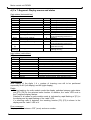
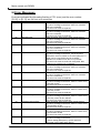
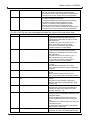
9) Error Messages
Errors are indicated by alternating flashing of "Er" (error) and the error number.
{Er.00} to {Er.13} are self-test error measures.
Error No.
00
Error description
ROM test
01
RAM test
02
Watchdog test
03
EEprom access
04
EEprom data
05
M1 current measurement
06
M2 measurement
07
Switch off relay M1
08
Switch off relay M2
09
Switch off relay M1+M2
10
Transistor switch off M1
11
Transistor switch off M2
12
Hardware SE
28 / 35
Action
Switch off power, wait 10 sec, switch power back on.
If the error message is still active, there is a hardware
error in the controller.
The control unit must be replaced.
Switch off power, wait 10 sec, switch power back on.
If the error message is still active, there is a hardware
error in the controller.
The control unit must be replaced.
Switch off power, wait 10 sec, switch power back on.
If the error message is still active, there is a hardware
error in the control unit.
The control unit must be replaced.
Switch off power, wait 10 sec, switch power back on.
If the error message is still active, there is a hardware
error in the control unit.
The control unit must be replaced.
Switch off power, wait 10 sec, switch power back on.
If the error message is still active, the saved menu
parameters, the force values or the travel paths are no
longer correct. Only [M.A0] can be accessed.
Adjustment to another menu item is not possible.
The control unit must be reset and re-adjusted. New
teaching runs must then be completed.
Switch off power, wait 10 sec, switch power back on.
If the error message is still active, there is a hardware
error in the control unit.
The control unit must be replaced.
Switch off power, wait 10 sec, switch power back on.
If the error message is still active, there is a hardware
error in the control unit.
The control unit must be replaced.
Switch off power, wait 10 sec, switch power back on.
If the error message is still active, there is a short-circuit
in the relay for M1.
The control unit must be replaced.
Switch off power, wait 10 sec, switch power back on.
If the error message is still active, there is a short-circuit
in the relay for M2.
The control unit must be replaced.
Switch off power, wait 10 sec, switch power back on.
If the error message is still active, there is a short-circuit
in the relay control for M1 and M2.
The control unit must be replaced.
Switch off power, wait 10 sec, switch power back on.
If the error message is still active, there is a short-circuit
in the transistor for M1.
The control unit must be replaced.
Switch off power, wait 10 sec, switch power back on.
If the error message is still active, there is a short-circuit
in the transistor for M2.
The control unit must be replaced.
Switch off power, wait 10 sec, switch power back on.
If the error message is still active:
a) Check setting [M.b6] and [J.1] with respect to
connected closing edge safety device.
Motor control unit DCM31
13
Hardware LS
b) Check connection of the closing edge safety device,
especially the earth connection at terminal [Kl.23].
c) If a) and b) correct, there is possibly a hardware error
in the control unit. The control unit must be replaced.
Switch off power, wait 10 sec, switch power back on.
If the error message is still active:
a) check setting [M.b4] and [M.C4] (external LS test)
with respect to connected photoelectric barrier.
b) Check connection of the photoelectric barrier,
especially earth connection at terminal [Kl.23].
c) if a) and b) correct, there is possibly a hardware error
in the control unit. The control unit must be replaced.
{Er.20} to {Er.29} are fault messages and show the cause of the last motor stop.
Fault No.
20
Fault message
No current in the startup motor 1
21
No current in startup motor 2
22
Motor stop by LS
23
Motor stop by SE
24
Motor stop due to exceeding of running
time
25
Emergency stop actuated
26
Electricity stop motor 1
27
Electricity stop motor 2
Action
Give renewed start command.
If gate travel interrupted again with error
message this means that no motor current
was measured.
a) Current of motor 1 is too low (<1A) =>
Motor and control unit do not match
b) no motor connected to [Kl.5]+[Kl.6].
c) Motor defective or cable break.
Give renewed start command.
If gate travel interrupted again with error
message this means that no motor current
was measured.
a) Current of motor 2 is too low (<1A) =>
Motor and control unit do not match
b) no motor connected to [Kl.5]+[Kl.6].
c) Motor defective or cable break.
Gate travel was stopped by actuation of the
LS input.
Check whether obstruction in the way.
If no, check photoelectric barrier and setting
of [M.b4]
Gate travel was stopped by actuating the SE
inputs.
Check whether obstruction in the way.
If no, check safety strip and setting of [M.b6]
Motor operation was longer than set in
[M.C5].
Check motor, transmission, emergency
release. If necessary adjust [M.C5] to gate
running time.
Gate travel was interrupted by actuation of
the emergency stop input or simultaneous
actuation of input A and input B (or radio
receiver channel 1 + 2).
The control unit stopped gate travel, as the
forces at motor 1 exceeded the teaching and
permitted values.
a) Check whether obstruction in the way.
b) Check gate leaf for smooth running and
M1.
c) Delete forces and travel path and carry out
new teaching runs.
d) Check force values in [M.A7] and [M.A8]
and increase if necessary.
The control unit has stopped gate travel, as
the forces at motor 2 exceeded the teaching
29 / 35
Motor control unit DCM31
28
30 / 35
Undervoltage
and permitted values.
a) Check whether obstruction in the way.
b) Check gate leaf for smooth running and
M2.
c) Delete forces and travel path and carry out
new teaching runs.
d) Check force values in [M.A9] and [M.b0]
and increase if necessary.
The supply voltage to the control unit is
temporarily or continuously too low.
Check mains connection.
Motor control unit DCM31
10) Technical Specifications
The control unit may only be used if the technical specifications are observed!
Parameter
Symbol
Power supply
Mains voltage
Umains
Mains frequency
Fmains
Secondary voltage
USec
Internal logic voltage
UV
Current input when idle
IR
Power input
PPrim
st
Start time voltage / 1 start
tStart
Inputs
Emergency stop not actuated
UEMERclosed
(closed)
Emergency stop actuated (open)
UEMERopen
Emergency stop current (closed)
IEMER
ES open / close not actuated
UESclosed
(closed)
ES open / close actuated (open)
UESopen
ES open / close current (closed)
IES
Photoelectric barrier not actuated
ULsclosed
(close)
Photoelectric barrier actuated
ULsopen
(open)
Photoelectric barrier short-circuit
ILSin-0
current
Photoelectric barrier reaction time
tLS-1
Photoelectric barrier reset time
tLS-0
SE (8K2) not actuated
RSE12-0
SE (8K2) actuated
RSE12-1
SE (OSE) level, release
USE12OSE-0
SE (OSE) frequency
fSE12OSE-0
SE reaction time
tSE12-1
SE reset time
tSE12-0
A / B not actuated (open)
UO-AB
A / B actuated (closed)
UCI-AB
A / B pulse duration (debounce)
TAB
NF Low level
VNFLow
NF High level
VNFHigh
Outputs
Voltage 12V output
U12V
Current 12V output
I12V
Voltage 24V output
U24V
Current 24V output
I24V
Motor current
IMotor
Current allowance value
IZug
Motor running time
tMot
Motor operating time
ED
OUT maximum voltage
UOut
OUT maximum current
IOut
Warning light output
PWarn
Radio (radio module mode)
Receiver data
Coding systems
Teaching capable transmission
buttons
Ambient conditions
Operating temperature
Storage temperature
Relative air humidity
Printed circuit board
Controller frequency
Length
Width
Height
Weight
Housing
Length
Width
Min.
190
48
18
4.8
Limit values
Typical
Max.
230
50
24
5.0
40
2.0
2.5
0.0
170
2.5
3.5
VAC
Hz
VAC
V
mA
VA
s
0.5
V
1.0
200
V
mA
0.5
V
1.0
V
mA
0.5
V
4.5
0.5
4.5
6.0
17.0
4.0
0.5
V
0.5
1.0
mA
25
250
8.2
50
350
13.0
5.5
1.0
2.0
50
350
ms
ms
KΩ
KΩ
V
KHz
ms
ms
V
V
ms
V
V
1.0
25
250
4.5
30
35
0.5
50
0.7
3.5
11.5
12.0
20
32
1.0
0.4
1
Ntransmitter
Toper
Tstor
RH
250
52
29
5.2
Units
-20
-25
20
12.5
40
39
200
11.0
5.0
100
25
30
4
500
VDC
mA
VAC
mA
A
A
S
%
V
A
W
40
Each
+50
+80
90
°C
°C
%
Test condition
At terminals 1 / 2
at terminals 32 / 33 at rest / at full load
terminals 32 / 33, no loads / cards
terminals 32 / 33, no loads / cards
@ USecondary = 24VAC
Via terminals 14 / 15
Terminal 15 / 0V
Via terminals 14 / 15
Terminal 16, 18, 19, 21 against 0V
Terminal 16, 18, 19, 21 against 0V
Via terminals 16/17, 18/17, 19/20, 21/20
Terminals 22 / 23
Terminal 22 against 0V
Via terminals 22 / 23
Time LS-command until motor switched
terminals 23 / 24
terminals 23 / 24
terminals 23 / 24
terminals 23 / 24
At 8K2 or OSE
At terminals 25 / 26, 27 / 26
At terminals 25 / 26, 27 / 26
@ UV = 5.0V, Pin14 of BL1
@ UV = 5.0V, Pin 14 of BL1
Full load / idle mode
Full load / idle mode
Adjustable via menu
At maximum motor current, max running time
At terminals 12 / 13
At terminals 12 / 13
At terminals 3 / 4
Depending on plug-in card radio module /
receiver
12- / 18-Bit linear, Keeloq (others on request)
Transmission buttons
In normal installed position
No condensation permitted!
fCont
LLP
BLP
HLP
mLP
4.19
110
166
45
320
MHz
mm
mm
mm
g
Internal PLL at 16.76MHz
LHous
BHous
255
176
mm
mm
Without cable entry
Without radio module, no other plug-in card
31 / 35
Motor control unit DCM31
Height
Weight
Material
Degree of protection
32 / 35
Hhous
Mhous
80
980
mm
g
incl. electronics, without toroidal transformer
ABS, self-extinguishing
IP54
Motor control unit DCM31
11) Notes
33 / 35
Motor control unit DCM31
12) Images/Diagrams
X1
X2
X3
inactive
X4
active
J1
X5
X6
34 / 35
Motor control unit DCM31
Ta.+
Ta.F
Ta.M
Ta.-
X7
Bl.1
Bl.2
X9
X8
X10
35 / 35