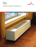
1
Installation Instructions
NOTE:
Read
installation.
the entire
instruction
manual
before
starting
the
suggestions
which will result in enhanced
installation,
reliability,
or
operation.
TABLE
OF CONTENTS
PAGE
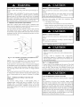
SAFETY
CONSIDERATIONS
INTRODUCTION
HEATER
........................
..................................
PACKAGES
INSTALLATION
..............................
Step 2 - Mount
Step 4 - Electrical
..........................
Step 6 - Refrigerant
Flow-Control
Step 7 - Condensate
Drains
Step 8 - Accessories
...............................
START-UP
CARE
AIRFLOW
PROCEDURES
Improper installation,
or use can cause
conditions
which
and Evacuation
Device
. ..
..............
Models
9
10
.......................
TABLES
10
................
or property
damage.
or your distributor
or
qualified
installer or
or accessories
when
modifying
this product.
Refer to the individual
packaged with kits or accessories when installing.
instructions
Follow all safety codes. Wear safety glasses and work gloves. Use
quenching
cloth for brazing
operations.
Have fire extinguisher
Read these
instructions
thoroughly
and follow
all
or cautions attached to the unit. Consult local building
codes
and
requirements.
Recognize
When
National
safety
Electrical
information.
you see this symbol
(NEC)
This is the safety-alert
for
for personal
Understand
words
special
symbol
on the unit and in instruction
be alert to the potential
the signal
Code
_.
manuals,
injury.
DANGER,
personal
injury
or
death.
CAUTION,
WARNING
signifies
hazards
which could result in personal injury or death. CAUTION
is used
to identify unsafe practices which may result in minor personal
injury
or product
and property
damage.
units are available
nominal
cooling
NOTE
and FH4C
are designed
for flexibility
or downflow
applications.
(kit required) and
These units are
for systems of 18,000 through
capacity.
Factory-authorized,
and
60,000
Btuh
field-installed
electric heater packages are available in sizes 5 through
Product Data literature for available accessory kits.
HEATER
30kW.
See
PACKAGES
factory-approved,
field-installed,
UL listed heater package
is
available from your equipment
supplier. See unit rating plate for a
list of factory-approved
heaters. Heaters
that are not factory
approved could cause damage which would not be covered under
the equipment
warranty.
If fan coil contains
a factory-installed
heater package, minimum
circuit ampacity (MCA) and maximum
fuse/breaker
may be different
than units with
a same
size
field-installed
accessory heater. The differences is not an error and
is due to calculation
is used to highlight
difference
per UL guidelines.
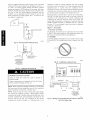
INSTALLATION
Step 1 -- Check Equipment
Unpack unit and move to final location.
not to damage unit.
Remove
carton taking
care
Inspect equipment for damage prior to installation. File claim with
shipping company if shipment is damaged or incomplete.
Locate
unit rating plate which contains
proper installation
information.
Check
WARNING,
and NOTE. These words are used with the safety-alert
symbol.
DANGER
identifies the most serious hazards which will result in
severe
FC4D
This unit may or may not be equipped
with an electric heater
package.
For units not equipped
with factory-installed
heat, a
adjustment,
alteration,
service, maintenance.
explosion,
fire. electrical
shock,
or other
injury
FA4C.
designed to meet the low air leak requirements
currently
in effect.
Because of this. the units need special attention in the condensate
pan and drain connection
area and when brazing tubing. These
10
CONSIDERATIONS
a qualified installer, service agency,
for information
or assistance.
The
must use factory-authorized
kits
available.
warnings
injury
INTRODUCTION
can be used for upflow, horizontal,
manufactured
and mobile
home
8
......................
personal
result in personal
Before installing or servicing unit. always turn off all power
to unit. There may be more than 1 disconnect
switch. Turn
off accessory heater power, if applicable.
7
7
.........................
may cause
could
4
7
.........................
PERFORMANCE
SAFETY
Consult
branch
agency
Connection
AND MAINTENANCE
HAZARD
2
......................
Tubing
of Operation
this warning
4
Step 5 - Refrigerant
Step 9 - Sequence
Failure to follow
or death.
1
................................
Connections
SHOCK
1
Unit ...............................
Step 3 - Air Ducts
ELECTRICAL
1
1
...................................
Step 1 - Check Equipment
1
rating plate to be sure unit matches
job specifications.
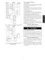
Step 2 -- Mount Unit
NOTE:
Unit can stand or lie on floor, or hang from ceiling
space for wiring, piping, and servicing unit.
IMPORTANT:
and/or
When
living
area,
unit
is installed
building
codes
over
or wall. Allow
a finished
may require
ceiling
a field-supplied
pan to be installed under the entire
allow as an alternative,
the running
separate,
secondary
condensate
additional
restrictions
or precautions.
A. Upflow
If return
Consult
local
unit.
of a
codes
for
air is to be ducted
through
a floor, set unit on floor over
opening and use 1/8 to 1/4" (3 to 6 mm) thick
gasket between duct, unit, and floor.
is a field option
dimensions.
required.
(See
C. Horizontal
Fig.
fireproof
on slope coil models.
1.) A field-supplied
KFAHD0101SLP
is also required
to
air
maintain
low
leak/low
for
sweat
Installation
Units must not he installed with access panels facing up or down.
The FH4C003
and 004 size units equipped with accessory cooling
coils are not approved
resilient
Cut opening
bottom
for horizontal
are factory built for horizontal
When suspending
unit from
suitable location
Fig. 2.)
Installation
Side return
kit number
applications
performance.
secondary
condensate
Some localities
may
line.
Gasket
all downflow
applications.
left installation.
ceiling, dimples
of screws for mounting
For horizontal
applications
having
All other
metal support
high
return
units
(See Fig. 2 and 3.)
in casing indicate
straps. (See
static
and humid
return air, the Water Management
Kit. KFAHC0125AAA.
need to be used to assist in water management.
may
per
closure
is
POWER ENTRY -OPTIONS
@R_MARY
018
O48
21'
(533
ram)
060
060
24" (610ram}
FRONT
RAiN
SERVICI
CLEARANCE
HANGING
UNIT
STRAPS
A
018
024
{?30
036
12" (305
ram)
17" (432
19" (483
ram)
ram)
018
048
21" {533
CLEARANCE
{FULL FACE
©F UNIT)
UPFLOW/DOWNFLOW
o2o°L
......
i" (38 ram)
19'
Oa3
m m)
--.._
ENTRY
OPTIONS
i
175" (44 ram)
F_ER ACCESS
CLEARANCE
UPFLOW/DOWNFLOW-SECONDARY
DRAIN
UPFLOW/DOWNFLOW
PRIMARY
ram)
060 060 24" {610 rr ,r')
FnONT SERVICE
DRA_N
j
SECONDARY
DRA_N
DRAIN
A07566
A07565
Fig. 1 - Slope
B. Downflow
Coil Unit in Upflow
Fig. 2 - Slope
Coil Unit in Horizontal
Left Application
Application
Installation
In this application,
field conversion
of the evaporator
is required
using accessory
downflow
kit along with an accessory
base kit.
Use fireproof
resilient gasket,
between duct, unit, and floor.
1/8
to
1/4"
(3 to 6 mm)
thick.
HORIZONTAL
UNIT
Failure
OR PROPERTY
DAMAGE
to follow this caution
HAZARD
may result in product
or property
CONNECTIONS
damage.
A00072
The conversion
of the fan coil to downflow
requires special
procedures for the condensate
drains on both A-coil and slope
units. The vertical drains have an overflow hole between the
Fig. 3 - A-Coil
Installation
To convert
Instructions
units
for downflow
supplied
with
applications,
kit for proper
refer
Left Application
(Factory
Ready)
primary and secondary drain holes. This hole is plugged for all
applications except downflow, but must be used for downflow.
During
the conversion
process,
remove
the plastic
cap
covering the vertical drains only and discard. Remove the plug
from the overflow
hole and discard. At completion
of the
downflow
installation,
caulk around the vertical pan fitting to
door joint to retain the low air leak performance
of the unit.
NOTE:
in Horizontal
PROPERTY
DAMAGE
Failure to follow
damage.
to
HAZARD
this caution may result
in product
or property
For optimum
condensate
drainage
performance
in horizontal
installations, unit should he leveled along its length and width.
installation.
For slope fan coils, use kit Part No. KFADC0201SLP.
For A-coils,
use kit Part No. KFADC0401ACL
Use fireproof resilient gasket.
NOTE:
1/8 to 1/4" (3 to d mm) thick, between
accommodates
duct, unit, and floor.
moved
Modular
separately
installation
units
can be
to installation
small
scuttle
sites. (See Fig. 4.)
disassembled
and
area for reassembly.
holes
and
limiting
components
This
process
entrances
to
4. Slide coil and pan assembly
5. Remove
horizontal
drain
out of unit.
pan
support
bracket
support rail on left side of unit and reinstall
rail on right side of unit. (See Fig. 7.)
6. Convert
air-seal
a. Remove
screws.
assembly
air-seal
for horizontal
assembly
from
coil
on coil support
right.
from coil by removing
4
(See Fig. 6.)
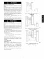
2SCREWS
b. Remove air splitter (B) from coil seal assembly by
removing 3 screws. (See Fig. 3-factory
shipped inset.)
c. Remove filter plate (A) and install air splitter (B) in
place of filter plate.
*_fREAR CORNER
BRACKET
d. Install filter plate (A) as shown in horizontal
application.
e. Remove condensate
tube sheets.
2SCREWS
CO]LBOX
troughs
right
(C) and install on opposite
f. Install hose onto plastic spout.
NORIZONTAL
RJGNT
ION
A95293
SUPPORT
Fig. 4 - Removal
Horizontal
Right
of Brackets
on Modular
Conversion
of Units With
kit
KFAHD0101SLP
NOTE:
Gasket
horizontal
slope coil conversion
number
to maintain
Units
Slope
RAIL
Coils
is required
low air leak/low
for
sweat
SUPPORT
performance.
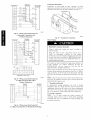
1. Remove
Fig. 5.)
blower
and coil access
panel and fitting panel.
(See
SUPPORT
BRACKET
2. Remove
coil mounting
right side casing flange.
screw
securing
coil
assembly
to
HORIZONTAL
3. Remove
HORIZONTAL
4. Lay fan coil unit on its right side and reinstall
with condensate
pan down. (See Fig. 5.)
5. Attach coil to casing
previously removed.
6. Make
RIGHT
coil assembly.
flange
using
door
screw
door is properly
seated
the low air leak rating
of the
to retain
from kit KFAHD
8. Align
with
connections,
tubing
and reinstall
Make sure liquid and suction
air leaks and cabinet
Right
Applications
Using
SUPPORTBRACKET
per kit instructions.
connections
and condensate
access panels
and fitting panel.
tube grommets
sweating.
for Horizontal
A-Coil
DRAIN PAN
7. Add gaskets
holes
A00071
Fig. 6 - Conversion
mounting
sure the pan cap in the fitting
on the fitting
unit.
coil
RIGHT
coil assembly
pan
are in place to prevent
Install after brazing.
A07571
Fig. 7 - Drain
7. Install horizontal
Pan Support
Bracket
pan on right side of coil assembly.
8. Slide coil assembly into casing. Be sure coil bracket
corner of vertical pan engages coil support rails.
A03001
Fig. 5 - Conversion
for Horizontal
Slope
Horizontal
Right
Conversion
Right
Applications
blower
2. Remove
Remove
metal clip securing
fitting panel.
3. Remove
2 snap-in
a
Coil
and coil access
panels.
A-Coils
A-coil
10. Remove
(See Fig. 6.)
fitting panel to condensate
clips securing
9. Reinstall 2 snap-in clips to correctly position and secure
coil assembly in unit. Be sure clip with large offsets is used
on right side of unit to secure horizontal
of Units With
1. Remove
Using
in unit.
on each
pan.
two oval fitting caps from the left side of the coil
door and fitting panel.
pan.
11. Remove
panel.
insulation
knockouts
on right side of coil access
12. Remove
2 oval coil access panel plugs and reinstall
holes on left side of coil access panel and fitting panel.
into
13.Installcondensate
panfittingcaps(fromitem10)in the
rightsideofthecoildoormaking
surethatthecapsnaps
andseats
cleanly
onthebacksideofthecoildoor.Make
sure
noinsulation
interferes
withseating
ofthecap.
14.Reinstall
access
fittingpanels,
aligning
holes
withtubing
connections
andcondensate
panconnections.
Besureto
reinstall
metalclipbetween
fittingpanelandvertical
condensate
pan.
Make
sure
liquidandsuction
tubegrommets
areinplace
toprevent
airleaks
andcabinet
sweating.
D. Manufactured
1. Fan
and Mobile
coil
unit
field-supplied
must
Home
be
Housing
secured
Applications
to the
structure
using
hardware.
2. Allow a minimum
panels.
3. Recommended
of 24" (610 mm) clearance
method of securing
for typical
from access
applications:
insulation lining. As an alternative,
fibrous ductwork may be used
if constructed
and installed in accordance
with the latest edition of
SMACNA
construction
standard
on
fibrous
glass
acoustical lining and fibrous ductwork
shall comply
Fire Protection Association
as tested by UL Standard
1 air ducts.
Step
4 --
Electrical
ducts.
Both
with National
181 for Class
Connections
All products from the factory utilize a printed-circuit
board (PCB)
which has a low voltage circuit protective fuse (5 amp), fan motor
speed tap selection
jumper. To disable
terminal
the TDR
(SPT), and time delay relay (TDR)
feature, sever the jumper wire JW1.
(See Fig. 9 and 10.)
When a factory-approved
accessory
control package
has been
installed,
check all factory wiring per unit wiring diagram and
inspect factory wiring connections
to be sure none were loosened
in transit or installation.
see unit rating plate.
If a different
control
package
is required,
a. If fan coil is away from wall. attach pipe strap to top of
fan coil using no. 10 self-tapping
screws. Angle strap
down and away from back of fan coil, remove all slack,
and fasten to wall stud of structure using 5/16-in.
lag
screws.
Typical
both sides of fan coil.
b. If fan coil is against
wall, secure
fan coil to wall stud
using 1/8" (3 mm) thick right-angle
brackets.
brackets to fan coil using no. 10 self-tapping
and to wall stud using 5/16-in.
4" (102mm)
(See Fig. 8.)
MAX
SECURE
UNIT
lag screws.
Attach
screws
FAN
AWAY
COILTO
FROM
PIPE STRAP
(TYPICAL
BOTH
x,,.
STRUCTURE
WALL
SIDES)
oR
NIT_LNA_AGAI
NST WALL
125' (3mm)
MOUNTING BRACKET
(TYPICAL BOTH BIDES)
A03010
Fig. 9 - Fan
(:oil Printed
Circuit Board
Models
for FA4C
and FH4C
DOWN FLOW
(KFACB)
SECURE UNIT TO FLOOR
ANGLE BRACKET OR PIPE STRAP
f
4" (102ram)
MAX
0
<t
tH
A07567
Fig. 8 - A-Coil
Step 3
--
Connect
provided
Air
I
Use flexible
transmission
heat-resistant
unit
at discharge
equipped
space
with
connection.
must
I0
Acoustical
Ductwork
be insulated
20-30kW
mm) clearance to combustible
of supply duct.
Ductwork
and seal duct-to-unit
joint.
install
factory-authorized
connectors
between
ductwork
and unit to prevent
of vibration.
When electric heater is installed,
use
material for flexible
connector
between
ductwork
unconditioned
barrier.
Units
0
supply-air
duct over the outside of 3/4" (19 mm) flanges
on supply-air
opening.
Secure duct to flange, using
proper fasteners for type of duct used,
If return-air
flanges
are required,
accessory kit.
and
.@
Ducts
electric
materials
passing
and covered
heaters
require
through
with
vapor
a 1" (25
for the first 36" (914 mm)
Treatment
Metal duct systems that do not have a 90 ° elbow and 10' (3m) of
main duct to first branch takeoff may require internal acoustical
@ggozi
Id33
A05181
Fig. 10 - Fan
(:oil Printed Circuit
for FC4D Model
Board
FAN
THERMOSTAT
PROPERTY
DAMAGE
Failure to follow
damage.
If a disconnect
where drill
components.
Before
HAZARD
this caution
may result in product
R
]
.....
]
.....
[]
or property
COIL
(CONTROL)
W2
w3
switch
is to be mounted
or fastener
will
on unit, select
not contact
electrical
a location
E
or refrigerant
_x
proceeding
with
electrical
connections,
make
certain
z_
C
AiR COND.
that
supply voltage, frequency, phase, and ampacity are as specified on
the unit rating plate. See unit wiring label for proper field highand low-voltage
wiring.
Make
all electrical
connections
in
accordance
with the NEC and any local
may apply. Use copper wire only.
The unit must have a separate
field-supplied
disconnect
switch
readily
On
accessible
units
codes
branch
located
or ordinances
that
electric circuit with a
within sight from, and
A94058
Fig. 11 - WMng
Air Conditioning
Only)
FAN
THERMOSTAT
from, the unit.
with
Layout
(Cooling
Unit
COIL
(CONTROL)
2z_ RED R
a factory-installed
disconnect
with
pull-out
removed, service and maintenance
can be safely performed
the load side of the control package.
£_
on only
GRY
_W
3wriT
G
Writ
W2
E
ELECTRICAL
Failure
death.
SHOCK
to follow
HAZARD
this warning
AIR COND.
could
result in personal
Field wires on the line side of the disconnect
unit remain
maintenance
injury
or
found in the fan coil
live, even when the pull-out
is removed. Service and
to incoming
wiring cannot be performed
until the
main disconnect
switch (remote
to the unit) is turned
A94059
off.
Fig. 12 - Wiring
A. Line
Voltage
If unit will
power
Connections
contain
plug from
For units without
yellow
NOTE:
ground
Units
opening.
This
condensation.
will
B. 24-v
Control
male plug
harness.
(See
metal
reduce
heater
Electric
to
HEAT
PUMP
SONTR
Heater
z;_
power
leads
from
field
disconnect
to
]
.........................
c
L)
R
without
WHI
air leakage
W2
lug.
electric
block-off
C
.........
leads.
plate
heat
should
covering
and formation
have
the
a
heater
[]
[]
/
v_° Z__
E -
W2
of exterior
]
O
.........
System
in accordance
with wiring
label on the blower.
(See Fig. 11 through 16.) Use no. 18 AWG color-coded,
insulated
(35°C
minimum)
wire to make the low-voltage
connections
between the thermostat,
the unit, and the outdoor equipment.
If the
is located more than 100' (30
along
the low-voltage
wire),
m) from the unit (as
use no. 16 AWG
color-coded,
insulated (35°C minimum) wire. All wiring must be
NEC Class 1 and must be separated from incoming power leads.
Refer to outdoor
procedure
Heat)
FAN COIL
(CONTROL)
THERMOSTAT
Unit
To Unit
Wire low voltage
thermostat
measured
and 1-Stage
and discard
from
Air Conditioning
_G
wire to unit ground
installed
sheet
remove
heater:
208/230v
field-supplied
Connection
wiring
and black stripped
2. Connect
heater,
fan coil and connect
electric
1. Connect
(Cooling
accesso W electric
female
plug from unit
Installation
Instructions.)
Layout
unit wiring
recommendations.
instructions
for any additional
wiring
A94060
Fig. 13 - Wiring
(Cooling
Layout
and 2-Stage
No Outdoor
Heat Pump
Heat with
Thermostat)
Unit
THERMOSTAT
Transformer
FAN COiL
(CONTROL)
HEAT PUMP
(CONTROL)
.............................
R
[]-
Transformer
applications,
transformer
Information
is factory-wired
for 230v
operation.
disconnect
the black wire from the 230v
and connect
it to the 208v
terminal.
For 208v
terminal on
(See Fig. 17.)
4::3_c
E
[]
[]
[]-
RED
g: y
A94061
Fig. 14 - Wiring
Layout
Heat Pump
[;nit
(Cooling and 2-Stage
Heat with
1 Outdoor Thermostat)
A05182
Fig. 17 - Transformer
FAN COIL
(CONTROL)
THERMOSTAT
Heater
HEAT PUMP
(CONTROL)
Connections
Staging
G
t. c
PROPERTY
DAMAGE
Failure to follow
property damage.
w3W2BLUvlo
_
this
If W2. W3, and E on
30kW)
are individually
thermostats
or any other
be used. This relay is in
normally
used with kit
........
outdoor
thermostat
HAZARD
caution
may
result
in product
or
any 3 stage heater (18, 20, 24, or
connected
as with
outdoor
situation, emergency heat relay must
kit Part No. KHOT0201SEC
and is
Part No. KHAOT0301FST
for 2
systems.
The controls are factory circuited for single-stage
2-stage
operation,
use
outdoor
thermostat
operation.
kit
Part
For
No.
KHAOT0301FST.
KHAOT0201SEC
kits
No.
When
2 stages
and for 3-stage
and KHAOT0301FST.
are desired,
use
both
Part
cut W3 at the W2 wire nut.
strip and
reconnect per the thermostat kit instruction.
(See Fig. 14.) When 3
stages are desired, cut the W2 wire nut off and discard. Strip W2.
W3, and E and reconnect per thermostat kit instructions.
(See Fig.
EMERGENCY
HEAT
RELAY
15.)
A94062
Fig. 15 - Wiring
Layout
Heat Pump
[;nit
FAN COIL
(CONTROL)
When
HEAT PUMP
(CONTROL)
[]...........................................
o
C. Manufactured
Housing
In manufactured
Regulations,
Title
housing
applications,
24. Chapter XX. Part
supplemental
D. Ground
connecting
.......................................................................................................................
(Cooling
and 2-Stage
Layout
Heat Pump
Heat for Manufactured
[;nit
Housing)
electric
heat
be locked
is not
kit Part No.
tire Code
of Federal
3280.714
requires that
out at outdoor
temperatures
Connections
Use
UL-listed
supply
wire(s)
conduit
to unit
Grounding
may also be accomplished
provided in control box.
0
A03088
Fig. 16 - Wiring
the E terminal
above 40°F (4°C), except for a heat pump defrost cycle. Refer to
Fig. 16 for typical low voltage wiring with outdoor thermostat.
NOTE:
]
3 stages are used or anytime
tied to W2. the emergency
heat relay, part of outdoor
KHAOT0201SEC
must be used.
(Cooling and 2-Stage
Heat with 2
Outdoor Thermostats)
THERMOSTAT
NOTE:
and
conduit
to obtain
connector
proper
by using
for
grounding.
grounding
lugs
ELECTRICAL
SHOCK
HAZARD
Failure
tofollowthiswarning
couldresult
inpersonal
injuryor
death.
According
toNEC,ANSI/NFPA
70,andlocalcodes,
thecabinet
musthaveanuninterrupted
orunbroken
ground
tominimize
personal
injuryif anelectrical
faultshould
occur.
Theground
mayconsist
ofelectrical
wireormetal
conduit
wheninstalled
in
accordance
withexisting
electrical
codes.
If conduit
connection
uses
reducing
washers,
aseparate
ground
wiremust
beused.
E. Minimum
CFMand Motor Speed Selection
Units with or without
Refer to the unit wiring
electric heaters require a minimum
CFM.
label to ensure that the fan speed selected is
not lower than the minimum
Fan speed
selection
fan speed
for FA4C
PRODUCT
Failure to follow
damage.
A brazing
brazed
surface
HAZARD
this caution
shield
MUST
may result in product
be used
when
1. Cut tubing
to correct
liquid
3. Braze connection
brazing
below
materials.
800°F
or property
sets are being
damage
tube
to the unit
connections.
Make
length.
2. Insert tube into sweat connection
is done at the fan
tubing
to the unit connections
to prevent
and condensate
pan fitting caps.
Units have sweat suction
and
suction tube connection
first.
indicated.
and FH4C models
DAMAGE
on unit until it bottoms.
using silver bearing
or non-silver
Do not use solder (materials
/ 427°C).
Consult
bearing
which
melt
local code requirements.
relay printed-circuit
board. To change motor speeds, disconnect
fan lead used on relay terminal (SPT) and replace with motor speed
tap desired. (See Fig. 18.) Save
lead removed from relay.
insulating
cap and place on motor
PRODUCT
Failure
DAMAGE
to follow
HAZARD
this caution
may result in product
or property
damage.
Wrap a wet cloth around rear
TXV and factory-made
joints.
Step 6 -- Refrigerant
PRODUCT
_AN
A97529
Fig. 18 - Fan
NOTE:
('oil
Relay and Speed Tap Terminal
and FH4C Models
In low static applications,
be used to reduce possibility
Some
units have 3 motor
lower
motor
of water being
blown
speed taps. Low speed
for FA4C
speed
(red) is designed
systems.
selection
on the FC4D
models
to prevent
damage
to
Device
HAZARD
this caution
may result in improper
product
If using
a TXV
in conjunction
with
a single-phase
reciprocating
compressor,
a compressor
start capacitor and
relay are required. Consult outdoor unit pre-sale literature for
start assist kit part number.
tap should
off coil.
for mismatched
outdoor unit applications.
Medium speed (blue) is
designed for straight matched
operations.
High speed (black) is
used with high external static duct systems of straight matched
The fan speed
Flow-Control
OPERATION
Failure to follow
operation.
DEC_
of fitting
Step 7 --
Condensate
To connect
drains,
Drains
the cap openings
must be removed.
Use a knife
to start the opening near the tab and using pliers, pull the tab to
remove the disk. Clean the edge of the opening if necessary and
install the condensate
line. Finally caulk around the lines where
they exit the fitting to retain the low leak rating of the unit.
is done at the motor.
To change motor speeds, disconnect fan lead from terminal 2 and
move to desired speed tap; Low speed (1), Medium (2), and High
(3).
Step 5 -Evacuation
UNIT
Refrigerant
Tubing
Connection
Use accessory
tubing
package
or
refrigerant
grade. Suction
tube must
damaged,
refrigerant
field-supplied
be insulated.
dirty, or contaminated
tubing
flow-control
device. ALWAYS
field-supplied
tubing
service valves.
to 500 microns
and
before
because
evacuate
opening
OR PROPERTY
Failure to follow
damage.
tubing
Do not
of
use
it may plug
the coil and
outdoor
unit
DAMAGE
this caution
HAZARD
may result in product
or property
The conversion
of the fan coil to downflow
requires special
procedures
for the condensate
drains on both A-coil and slope
units. The vertical drains have an overflow
hole between
the
primary and secondary
drain holes. This hole is plugged for all
applications
except downflow,
but must be used for do,_vnflow.
During the conversion
process, remove the plastic cap covering
the vertical drains only and discard. Remove the plug from the
overflow
hole and discard. At completion
of the downflow
installation,
caulk around the vertical pan fitting to door joint to
retain the low air leak perfornrance
of the unit.
Unitsareequipped
withprimary
andsecondary
3/4-in.FPTdrain
connections.
Forproper
condensate
lineinstallations
see
Fig.1,2,
3,5 and6.Toprevent
property
damage
andachieve
optimum
drainage
performance.
BOTHprimary
andsecondary
drainlines
should
beinstalled
andinclude
properly-sized
condensate
traps.
(SeeFig.19and20.)Factory-approved
condensate
trapsare
available.
It is recommended
thatPVCfittingsbeusedonthe
plastic
condensate
pan.Finger-tighten
plus1-1/2turns.
Donot
over-tighten.
Usepipedope.
alternative
to using
an external
may allow the use of a separate
condensate
pan.
some
localities
3/4" (19 mm) condensate
line (with
appropriate
noticeable.
trap) to a place where
the condensate
The owner of the structure must be informed
will be
that when
condensate
flows from the secondary
pan, the unit requires
servicing
Install traps in the condensate
drain or external
or water damage
condensate
will occur.
lines as close to the coil as possible.
(See Fig. 20.) Make sure that the outlet of each trap is below its
connection
to the condensate
pan to prevent
condensate
from
overflowing
the drain pan. Prime all traps, test for leaks, and
insulate traps if located above a living area. Condensate
drain lines
UNIT
should be pitched downward at a mininmm
slope of 1" (25 mm)
for every 10' (3 m) of length. Consult local codes for additional
restrictions
or precautions.
f
2" MtN
(51 mm)
;mm,
Step
A.
8 --
Accessories
Electronic
Air Cleaner
The Electronic Air Cleaner may be connected
to fan coil as shown
in Fig. 22. This nmthod requires a field supplied transformer.
See
Electronic Air Cleaner literature for kit requirements.
B. Humidifier
A03002
Fig. 19 - Recommended
Condensate
Connect humidifier and humidistat to fan coil unit as shown in Fig.
23 and Fig. 24. The cooling lockout relay is optional.
(See Fig.
23.)
Trap
s
PANEL
-
SECONDAR
Y DRA_N
APPROPRIATE
(USE
PRIMARY
/USE
FFELD
TRAP
RE
FACTORY
SUPPLIED
SUFFICIENT
STANDARD
[RE_
KiT
FIELD
WITH
TRAP
FACTORY
REQUFRED
DO
KIT OR
SUPPUED
NOT
USE SHALLOW
RUNNtNG
TRAPSf
TRAP)
OR
A03013
TRAP OF
DEPTH
P TRAPS
Fig. 21 - Insufficient
ARE
Condensate
Trap
NOT $U FF_C[ENT
SEE
FIGURE OF RFCOMMENDED
CONDENSATE
TRAP)
CONTROL BOARD
A03003
Fig. 20 - Condensate
PROPERTY
DAMAGE
Failure
to follow
property
damage.
Shallow
running
proper condensate
Trap
C C C
and Unit
HAZARD
this
caution
may
result
in product
traps are inadequate
and DO NOT
drainage. (See Fig. 21.)
or
allow
BLOWER
NOTE:
When
connecting
filter access panel,
thus preventing
prinm both primary
NOTE:
from
drain lines,
filter removal.
and secondary
If unit is located
may result
condensate
condensate
in or above
condensate
a living
overflow,
avoid
blocking
After connection,
TO EAC
a field-supplied,
external
pan should
be installed
underneath
the entire unit. and a
condensate
line (with
appropriate
trap)
from
unit
condensate
pan
the
should
pan.
Any
be drained
condensate
to a noticeable
should
in this
place.
FROM MOLEX
PLUG AND
TRANSFORMER
(IN UNIT)
damage
secondary
into
TOMoToRTRANSPORMER
_
'_
COM
traps.
space where
condensate
the
"
be run
external
As an
A03011
Fig. 22 - Wiring
Layout
of Electronic
for FY4A
Models
Air Cleaner
Only
to Fan
Coil
FAN COIL
(CONTROL)
THERMOSTAT
HEAT PUMP
(CONTROl_)
R
A.
Continuous
Thermostat
Fan
closes
R to G. G energizes
fan relay
completes circuit to indoor blower motor. When
there is a 90-sec delay before relay opens.
[]g: c
[]
[]
[]
Step 9 -- Sequence of Operation
B. Cooling
before
E
w2
i
I
i
i
i
z2x
DI
i
L .....
Mode
fan relay opens.
C. Heat Pump
Mode
o
Y
de-energized,
ther is a 90-sec
i
i
I
I
D. Heat Pump
Heating
delay before
with Auxinary
fan relay opens.
Electric
Heat
Thermostat
energizes R to G, R to Y, and R to W. G energizes fan
relay on PCB which completes
circuit to indoor blower motor. W
,,,,
energizes
[--
Heating
Thermostat
energizes R to G and R to Y. G energizes fan relay on
PCB which completes circuit to indoor blower motor. When G- is
i
RELAY
electric
heat relay(s)
which
completes
circuit
to heater
element(s).
When W is de-energized,
electric heat relay(s) open,
turning
off heater elements. When G is de-energized
there is a
--
1
I
which
Thermostat
energizes R to G. R to Y. and R to O (heat pump only).
G energizes
fan relay on PCB which completes
circuit to indoor
blower motor. When G is de-energized,
there is a 90-sec delay
W3
1
on PCB
G is de-energized,
90-sec
HUM D STAT
delay before
fan relay opens.
I
E. Electric
Heat
or Emergency
Heat
Mode
Thermostat
closes R to W. W energizes electric heat relay(s) which
completes circuit to heater element(s).
Blower motor is energized
through normally
closed
contacts
on fan relay. When W is
de-energized,
A95294
Fig. 23 - Wiring
Layout
of Humidifier
to Heat
Pump
heat relay(s)
opens.
PROCEDURES
Refer to outdoor unit Installation
Instructions
for system
instructions and refrigerant charging method details.
FAN COIL
(CONTROL)
THERMOSTAT
electric
START-UP
start-up
..............
R
..............
G
w2
,_N
C
i
COMPONENT
HAZARD
Failure
to follow this caution
may result in product
damage.
Never operate unit without a filter. Damage to blower motor
or coil may result. Factory authorized filter kits must be used
when locating the filter inside the unit. For those applications
where
access
to an internal
filter
is impractical,
a
field-supplied
filter must be installed
in the return duct
system.
AIR CGND.
i
--
UNIT
i
i
CARE AND MAINTENANCE
i
To continue high performance
and minimize
possible equipment
failure, it is essential that periodic maintenance
be performed
on
this equipment.
Consult
frequency of maintenance
Ag52g5
Fig. 24 - Wiring
Layout of Humidifier
With Electric Heat
to Fan Coil
your local
contract.
dealer
as
to
the
proper
The ability to properly perform maintenance
on this equipment
requires certain mechanical
skills and tools. If you do not possess
these, contact your
service recommended
on a monthly
basis.
dealer for maintenance.
The only consumer
or required is filter replacement
or cleaning
AIRFLOW
PERFORMANCE
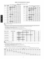
Table
FC4C
SIZE
BLOWER
SPEED
TOTAL EXTERNAL
1 - Airflow
0.20
(in. we)
0.30
0.40
Medium
Low
(CFM)
614
659
572
619
530
578
486
538
441
024
High
Medium
Low
823
633
905
786
583
868
747
533
830
707
482
030
High
Medium
Low
1130
1033
840
1097
1000
802
1063
965
760
High
Medium
1282
i"398
1238
Low
FA4A
SIZE
BLOWER
SPEED
499
396
018
High
Low
792
665
431
753
622
378
O24
1028
928
713
992
888
663
955
846
609
O36
1354
1192
1308
1142
1257
1090
1204
1036
042
H gh
036
Performance
STATIC PRESSURE
0.10
018
TABLES
0.50
0.60
666 819 566
TOTAL EXTERNAL STATIC PRESSURE
(in. wc)
0.10
0.20
0.30
0.40
0.50
0.60
620
588
538
607
468
504
380
1070
910
878
1032
888
818
978
849
860
754
908
791
793
686
822
715
724
614
721
621
High
Low
1352
1137
1316
1112
1273
1081
1223
1043
1167
998
1103
946
High
Medium
1576
1_
_02
1540
1488
1521
1421
1426
1338
1316
1239
1388
633
High
Low
High
Low
O3O
05_
1168
1118
1067
1014
959
903
Low
1330
1278
1209
1124
042
High
Medium
Low
1479
1303
1578
1437
1258
1533
1392
1211
1480
1344
1161
1420
1293
1108
1353
1240
1054
048
High
Medium
Low
_9C_2 _824
_30:i762
1825
1584
1743
1690
1531
1659
1611
1465
1571
1527
1387
1479
1436
1296
048
High
Medium
Low
1805
1652
1458
1772
1617
1418
1739
1581
1377
1704
1543
1335
1669
1504
1292
1632
1463
1248
060
High
Medium
Low
28
1959
1748
1965
1829
1659
1875
1750
1598
1778
1663
1525
1674
1566
1442
High
Medium
1799
1766
1989
1731
1954
1695
1916
1658
1878
1618
1667
1633
1596
1558
1517
1475
060
Low
Airflow
-
outside
450
1367
_06_
1898
1709
cfm/ton.
NOTES:
1, Airflow based upon dry coil at 230v with factory-approved
filter and electric heater (2 element heater sizes 018 through 036, 3 element heater sizes 042
through 060). Airflow at 208 volts is approximately
10% lower for FA4A models. For FC4D models, airflow at 208 volts is approximately the same as 230
volts because the X13 motor is a constant torque motor. The torque doesn't drop off at the speeds the motor operates,
2. To avoid potential for condensate blowing out of drain pan prior to making drain trap:
-Return static pressure must be less than 0.40 in. wc.
-Horizontal
applications of 042 - 060 sizes must have supply static greater than 0.20 in. wc.
3, Airflow
above 400 ofm/ton on 048-060
MODEL & SIZE
size could result in condensate
BLOWER SPEED
FH4C 001 with
FH4C 002 with
_34
690
1352
1137
Low
FH4C 003 with
High
Medium
KFAEC0901048
FH4C 004 with
STATIC PRESSURE
0.4
(in. we)
0.5
0.6
86o
793
686
724
614
878
818
754
666
633
591
1316
1112
iiiil}iiiiii,ii,ll,ii,liiiiill"830)il}})ii_i!;ll_i!;li)ii!;ii
1763
1625
1584
Low
iiii;iiiiii;li;iii ii !!i!i!!!!!!!!!!!i!;!
ii 811i iiiilii i;i i
High
Medium
Low
KFAEC1001060
out of drain pan.
476
1247
538
1322
High
Medium
KFAEC0801036
TOTAL EXTERNAL
0.2
0.3
0.1
High
Medium
Low
KFAEC0701024
blowing off coil or splashing
1273
1081
1223
1043
1167
1743
1690
1659
1611
1571
1527
1479
1436
1531
1465
1387
1296
1875
1750
1778
1663
1674
1566
1598
1525
1442
1959
1898
1965
1829
1748
1709
1659
1103
946
998
- Airflow outside 400 cfm/ton.
NOTES:
1, Airflow based upon dry coil at 230v with factory-approved
accessory filter
heat, sizes 003 and 004). Airflow at 208 volts is approximately 10% lower.
2. To avoid potential for condensate blowing out of drain pan prior to making
-Return static pressure must be less than 0.4 in. wc.
-Horizontal
applications of 048-070 sizes must have supply static greater
3, Airflow above 400 ofm/ton on 004 size could result in condensate blowing
Table
FA, FC
SIZE
018
024
030
036
042
048
060
2 -AirDelivery
500
600
0.034
0.049
0.016
0.027
......
..........
..............
..................
......................
Performance
700
0.063
0.038
800
Con_cfion
900
1000
Component
1100
..........................
0.049
0.059
......................
0.049
0.059
0.070
0.080
0.055
0.064
and electric heater (lO-kW
electric heat, sizes 001 and 002; 15-kW
electric
drain trap:
than 0.20 in. wc.
off coil or splashing
Pl_ssure
Drop
CFM
1200
1300
..................
0.073
0.081
0.049
0.056
10
out of drain pan.
(in. wc)atIndicatedAirflow
1400
1500
..............
0.063
0.070
0.038
0.043
1600
(Dry toWer
(:oil)
1700
1800
1900
2000
..........
0.049
0.054
0.027
0.031
0.059
0.035
....
0.039
0.043
Table
3 - Factol_,-Installed
0.092
800
1000
CFM
1200
1400
0.075
0.110
0.072
0.100
600
0.044
001
002
003
004
Table
(in. wc)
1400
0.075
0.048
-
400
Drop
0.100
0.070
800
0.044
0.022
FH4C
UNIT SIZE
Pressure
0.072
0.051
600
0.020
-
Static
1000
400
018
024,030
036,042,048
060
Filter
CFM
1200
FA, FC
SIZE
4 - Electric
Heater
Static Pressure
1600
0.120
0.086
0.152
0.105
0.130
1600
1800
2000
0.120
0.120
0.152
0.152
0.187
(in. wc)
FA, FC
018 - 036
FH4C
FA, FC
042 - 060
FH4C
001,002
003,004
kW
EXTERNAL STATIC
PRESSURE
CORRECTION
HEATER
ELEMENTS
0
0
+.02
1
2
3
4
3, 5
8,10
9, 15
20
+.01
0
.02
.04
HEATER
ELEMENTS
2000
-
0.130
0.092
Drop
1800
kW
EXTERNAL STATIC
PRESSURE
CORRECTION
0
0
+.04
2
3
4
6
8, 10
9,15
20
18, 24, 30
+.02
0
.02
.10
The airflow performance data was developed using fan coils with 10-kW electric heaters (2 elements) in FA4C / FC4D sizes 018 through 036 and FH4C sizes
001 and 002 and 15-kW heaters (3 elements) in FA4C / FC4D sizes 042 through 060 and FH4C sizes 003 and 004. For fan coils with heaters of a different number of elements, the available external static at a given CFM from the curve may be corrected by adding or subtracting available external static pressure as indicated above.
11
Copyright
2007 CAC / BDP •
Manufacturer
reserves
7310 W. Morris
St. •
indianapolis,
iN 46231
the right to change_ at any time_ specifications
Printed
and designs
in US.A.
without
Edition
notice and without
12
Date:
06/07
obligations.
Catalo_l No: IM-FA4C-03
Replaces:
IM- FA4C-02