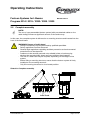
1
Operating Instructions
Festoon Systems for I-Beams
Program 0314 / 0315 / 0320 / 0325 / 0330
www.conductix.com
BAL0300-0007-E
Page 1 of 37
Operating Instructions
Festoon Systems for I-Beams
Program 0314 / 0315 / 0320 / 0325 / 0330
Contents
BAL0300-0007-E
Page
1
Target audience for operating instructions ............................................................... 4
2
General information ................................................................................................... 4
2.1
General safety information ........................................................................................ 4
2.1.1
Safety and hazard information .................................................................................. 4
2.2
General safety regulations and organization ............................................................. 5
2.3
Special safety notes .................................................................................................. 5
2.4
Information regarding protection from hazards ........................................................ 7
2.4.1
Mechanical hazards .................................................................................................. 7
2.4.2
Electrical hazards ...................................................................................................... 7
2.5
Technical status ........................................................................................................ 8
2.5.1
Technical Data........................................................................................................... 8
2.5.2
Repeat inspections.................................................................................................... 8
2.6
Intended use.............................................................................................................. 9
2.6.1
How to use the operating manual ............................................................................. 9
3
Special instructions ................................................................................................. 10
3.1
Track beam ............................................................................................................. 10
3.2
Complete assembly................................................................................................. 15
3.3
Adjusting the running gear of the cable trolleys ...................................................... 16
3.4
Attaching the end clamp to the beam ..................................................................... 16
3.5
Attaching the towing clamp to the crane towing arm ............................................. 18
3.6
Festoon systems with towing trolley, crane interface ............................................. 19
3.7
Running cables ........................................................................................................ 20
3.7.1
Running round cables ............................................................................................. 20
3.7.2
Arrangement of flat cables ...................................................................................... 21
www.conductix.com
Page 2 of 37
Operating Instructions
Festoon Systems for I-Beams
Program 0314 / 0315 / 0320 / 0325 / 0330
BAL0300-0007-E
3.8
Cable clamps .......................................................................................................... 22
3.8.1
Round cable clamps ............................................................................................... 22
3.8.2
Mounting the round clamps .................................................................................... 22
3.9
Spacers ................................................................................................................... 24
3.9.1
Flat cable clamp ...................................................................................................... 24
3.10
Towing rope ............................................................................................................ 25
3.10.1
Mounting the towing rope ....................................................................................... 25
3.10.2
Inspection of towing ropes and criteria for replacement ........................................ 26
3.10.3
Maintenance of towing ropes .................................................................................. 27
3.11
Damping devices..................................................................................................... 28
4
Commissioning the festoon system ........................................................................ 29
4.1
Inspections after installing the festoon system ....................................................... 29
4.2
Functional testing of the festoon system ................................................................ 29
4.3
Operating the festoon system ................................................................................. 29
5
Maintenance ............................................................................................................ 30
5.1
Inspection ................................................................................................................ 30
5.1.1
Inspecting the deactivated system ......................................................................... 30
5.1.2
Inspecting the activated system ............................................................................. 31
5.2
Service..................................................................................................................... 32
5.2.1
Wearing parts .......................................................................................................... 33
5.2.2
Wear Limits ............................................................................................................. 33
5.2.3
Spare parts .............................................................................................................. 34
5.3
Repair ...................................................................................................................... 34
6
Copyright ................................................................................................................. 35
7
Product observations .............................................................................................. 35
www.conductix.com
Page 3 of 37
Operating Instructions
Festoon Systems for I-Beams
Program 0314 / 0315 / 0320 / 0325 / 0330
1
BAL0300-0007-E
Target audience for operating instructions
The operating instructions are intended for qualified personnel who install the festoon
systems, operate them and who are familiar with the requirements regarding work safety
and accident prevention.
2
General information
2.1
General safety information
2.1.1
Safety and hazard information
The following symbols and designations are used in these operating instructions as safety
and/or hazard information:
WARNING! Bodily Harm!
Serious physical injury or fatal accidents may result if work and operating
instructions with this symbol are ignored or not followed properly. Notices in the
“Warning” category are to be strictly followed.
ATTENTION! Machine/Property Damage!
Serious machine or material damage may result if work and operating
instructions with this symbol are ignored or not followed properly. Notices in the
“Attention” category are to be exactly followed.
*
INFORMATION!
Work is facilitated if you follow advice and operational instructions with this
symbol.
INFORMATION!
Refers to another applicable document
www.conductix.com
Page 4 of 37
Operating Instructions
Festoon Systems for I-Beams
Program 0314 / 0315 / 0320 / 0325 / 0330
2.2
BAL0300-0007-E
General safety regulations and organization
The operating instructions must always be stored in a readily accessible on-site location
near the festoon system. In addition to the operating instructions, general regulations
regarding accident prevention and environmental protection are to be observed.
The operator must observe the following standards and regulations when operating a
festoon system:
98/37/EG
73/23/EWG
93/68/EWG
DIN EN ISO 12100
EU Machinery Directive
EU Low Voltage Directive
IEC 60038
Machine Safety
IEC standard voltages
IEC 60364
Electrical installations of buildings
IEC 60947
Low-voltage switchgear and controlgear
Accident prevention regulations
• Installation, set-up, maintenance and operation of the festoon system must be performed
by sufficiently qualified and trained specialists.
• Before beginning work, operation and maintenance personnel must have read and
understood the operating instructions and safety guidelines, in particular. Protective gear
for operation and maintenance personnel must be provided and used.
• The system operator or his/her representative is to supervise machine operation to
ensure the safety of personnel when working on or with the system.
2.3
Special safety notes
Transport / Installation:
• Individual parts and larger assembly groups are to be secured on suitable hoisting devices
or load-carrying equipment that are in good working order and have sufficient load
capacity.
For electrical and mechanical connections:
• Connections are only to be made by personnel specially trained for the given task.
For commissioning and operation:
• Before initial commissioning and daily start-up, a visual check and predefined inspection
procedure is to be performed (see Chapter 4).
• Any procedures that could threaten safety are to be avoided.
• The system should only be operated with functional protective gear and safety devices.
www.conductix.com
Page 5 of 37
Operating Instructions
Festoon Systems for I-Beams
Program 0314 / 0315 / 0320 / 0325 / 0330
BAL0300-0007-E
• Notify the responsible party immediately in case of damage to the festoon system.
• Protect the festoon system from accidental or unauthorized operation.
• It is forbidden to enter the operating area of the festoon system.
See also intended use in Chapter 2.6.
For cleaning / service / repair / maintenance / reconditioning:
• Turn off power supply and ensure that no inadvertent activation is possible.
• When installation tasks are carried out above eye level, use proper climbing aids and
working platforms.
• Do not climb on machine components.
• Check cables for wear or damage.
• Ensure that exhaust, collection and disposal of process materials be done in a safe and
environmentally-friendly manner.
• Safety devices that are removed for installation, service or repair must be remounted and
inspected after work is completed.
• Observe the inspection and maintenance intervals described in the maintenance
instructions.
• Observe the directions in the operating and maintenance instructions for replacing parts.
• Ensure that sufficient space for maintenance work is available.
• Ensure that the festoon system is not inadvertently activated during maintenance work.
• Ensure that detached parts do not fall.
• Screw joints that are disconnected during maintenance work are to be reattached and
secured as instructed.
• Fasteners and seals that cannot be reused are to be replaced (such as self-locking nuts,
disks, splints, O-rings, glued or microencapsulated screws).
• Lubrication points that are cleaned or wiped during maintenance and repair work must be
re-lubricated as instructed.
• After finishing work, collect all tools and materials and check that all are present.
• Disassembled parts and components that were replaced are to be collected, stored in a
safe place, recycled, or sent back.
www.conductix.com
Page 6 of 37
Operating Instructions
Festoon Systems for I-Beams
Program 0314 / 0315 / 0320 / 0325 / 0330
2.4
BAL0300-0007-E
Information regarding protection from hazards
Hazard areas must be identified with warning signs and be protected with barriers. Ensure
that hazard area notices are observed.
Hazards can result from
• improper use
• failure to adequately observe safety notices
• inadequate inspection and maintenance work
2.4.1
Mechanical hazards
WARNING! Bodily harm! Unconsciousness and injury due to
- crushing, pinching, cutting, wrapping
- retracting, blunt collision, stabbing, grinding
- slipping, stumbling, falling
Causes:
- Areas where danger of crushing, pinching and wrapping exists
- Part failure or explosion
Ways to protect yourself:
- Keep floors, devices, and machines clean.
- Repair leaks.
- Observe the required safety distance.
2.4.2
Electrical hazards
All errors must be analyzed before remedying the problem.
Work on electrical systems or production equipment may only be performed by specialized
electricians or persons under the supervision and direction of an electrician in accordance
with electrical rules (qualified personnel).
WARNING! Bodily harm!
Death due to electric shock, injury and burns due to
Touching live sources
Faulty insulation
Inadequate maintenance and repair
Short circuits
Causes:
- Touching or coming too close to uninsulated current-bearing parts
- Using uninsulated tools
- Current-bearing parts that are laid bare due to insulation failure
- Inadequate safety checks after maintenance work
- Use of improper fuses
www.conductix.com
Page 7 of 37
Operating Instructions
Festoon Systems for I-Beams
Program 0314 / 0315 / 0320 / 0325 / 0330
BAL0300-0007-E
Ways to protect yourself:
- Ensure that current to machines and system parts that are to undergo
maintenance work is turned off and protected against reactivation.
- Check parts to ensure that they are free of current. Cover and isolate nearby
live parts.
- Check electrical equipment regularly.
- Immediately replace loose or damaged cable or lines.
- Always replace blown fuses with identical fuses.
- Avoid touching live parts.
- Use insulated tools.
2.5
Technical status
These operating instructions were prepared in May 2007.
2.5.1
Technical Data
INFORMATION!
See project-specific technical documentation such as system sketches, cable
running suggestions, and round or flat cable clamp layout.
2.5.2
Repeat inspections
Every operator is to record all inspection, service and maintenance tasks in a machine book
in an orderly manner. This is to be confirmed by a technical expert. In case of inaccurate or
missing entries, the warranty is rendered null and void.
CAUTION! System or property damage!
Devices and systems are to be periodically inspected by an expert. In general,
visual and functional checks are to be performed. The condition of components
with regard to damage, wear, corrosion or other damage is to be determined.
Generally speaking, the completeness and functionality of the safety equipment
is evaluated. To better evaluate the wear and tear of parts, disassembly may be
required.
CAUTION! System or property damage!
All regular inspections are to be performed by the operator.
www.conductix.com
Page 8 of 37
Operating Instructions
Festoon Systems for I-Beams
Program 0314 / 0315 / 0320 / 0325 / 0330
2.6
BAL0300-0007-E
Intended use
The festoon system is built in accordance with recognized safety/technical regulations using
the latest technology and has been checked for safety compliance by the manufacturer.
Only festoon systems that are in good technical condition may be employed for their
intended use. These may only be operated by trained personnel aware of safe operating
practices and possible hazards. Intended use of the system also includes the observance of
manufacturer operation, service, and maintenance requirements. See Chapter 4.
Non-intended use includes the following:
• Exceeding projected load capacities
• Exceeding projected speeds
• Excessive braking deceleration
• Use of inappropriate cables (see also Chap. 2.5)
• Changing atmospheric conditions (including a change to projected physical location)
• Bridging and/or deactivating electrical sensors or switches
• Use of technically inappropriate guide systems (such as inappropriate or corroded track
beams, poorly aligned girder joints, etc.), see Chap. 2.1.
• The presence of projecting edges on the surrounding steel framework too close to the
cable trolley
The manufacturer is in no way liable for damages to the system or third parties resulting
from non-intended use.
2.6.1
How to use the operating manual
As a supplement to the operating instructions, the operator must observe the following
documentation (if available):
• Project-specific technical documentation
• Installation instructions, see Chap. 2
• Maintenance instructions, see Chap. 4
• Drawings
• Spare part lists
• Sketches
www.conductix.com
Page 9 of 37
Operating Instructions
Festoon Systems for I-Beams
Program 0314 / 0315 / 0320 / 0325 / 0330
3
Special instructions
3.1
Track beam
BAL0300-0007-E
The operator is basically responsible for ensuring that the track beam is securely fastened
as well as checking it for wear, corrosion or defects.
The following procedures are to be observed when installing the track beam:
CATION! System or property damage!!
- In general, track beams are to be protected from corrosion using appropriate
measures.
- The running surfaces of the main rollers and the horizontal guide rollers must
be clean and free of objects or defects that could damage the rollers
(scratches, cracks, holes, uneven segments, etc.).
- If multiple beams are welded together, they must all have the same
measurements and positional tolerances.
- The beam flanges are to be aligned with particular care in horizontal and
vertical planes.
- Track beams that have been damaged during transport or rolling must not be
used.
- Modified areas (from welding, sanding, etc.) on the track beam are to be
protected from corrosion with appropriate measures.
Sketch 1: Smoothing of welded track beams
CAUTION! System or property damage!
Bumps and uneven areas on all sides of the welded track beams are to be
sanded smooth for a length of 100 mm.
NOTE!
Required tools and materials:
*
sanded
sanded
sanded
www.conductix.com
sanded
Page 10 of 37
Operating Instructions
Festoon Systems for I-Beams
Program 0314 / 0315 / 0320 / 0325 / 0330
BAL0300-0007-E
Sketch 2: Use of even welded track beams
CAUTION! System or property damage!
Welded joints on the track beams must be even at points that could come into
contact with the cable trolleys. Fasteners and suspended objects that could
come into contact with the cable trolleys are not permitted
No uneven areas, fasteners, suspended
objects, etc.
Sketch 3: Girder joint for non-welded track beams:
CAUTION! System or property damage!
For non-welded girder joints, the gap between girders must not exceed 5 mm.
The cut is at a 45° angle.
*
NOTE!
Required tools and materials:
www.conductix.com
Page 11 of 37
Operating Instructions
Festoon Systems for I-Beams
Program 0314 / 0315 / 0320 / 0325 / 0330
BAL0300-0007-E
Sketch 4: Girder joint for non-welded track beams:
CAUTION! System or property damage!
For non-welded girder joints, the horizontal and vertical separation between
girders must not exceed 2 mm. Transitions must be ground smooth within
about 100 mm of the beginning of the cut. All transitions must be beveled and
rounded
*
NOTE!
Required tools and materials:
Horizontal and vertical
deviation ±2 mm
Edges beveled and
rounded
Edges beveled
and rounded
Smooth and clean the transitions in all directions up
to 100 mm away from the beginning of the cut!
www.conductix.com
Page 12 of 37
Operating Instructions
Festoon Systems for I-Beams
Program 0314 / 0315 / 0320 / 0325 / 0330
BAL0300-0007-E
Sketch 5: Horizontal deviation of track beams
CAUTION! System or property damage!
The horizontal deviation over the length of the track beam may not exceed
±5 mm. For lengths shorter than 2 m, deviation may not exceed ±2 mm.
*
NOTE!
Required tools and materials:
Sketch 6: Vertical deviation of track beams
CAUTION! System or property damage!
The vertical deviation over the length of the track beam may not exceed ±5
mm. For lengths shorter than 2 m, deviation may not exceed ±2 mm.
www.conductix.com
Page 13 of 37
Operating Instructions
Festoon Systems for I-Beams
Program 0314 / 0315 / 0320 / 0325 / 0330
BAL0300-0007-E
Sketch 7: Poor horizontal alignment between the operator’s crane beam and the track
beam
CAUTION! System or property damage!
The horizontal alignment gap between the crane beam and track beam must
not exceed ±7.5 mm. This tolerance should include a possible alignment
deviation of the trolley winch.
*
NOTE!
Required tools and materials:
Crane beam
Track beam
Sketch 8: Poor vertical alignment between the crane beam and track beam
CAUTION! System or property damage!
The horizontal alignment gap between the crane beam and track beam must
not exceed ±15 mm. This tolerance should include a possible alignment
deviation of the main trolley of the crane.
Crane beam
Track beam
www.conductix.com
Page 14 of 37
Operating Instructions
Festoon Systems for I-Beams
Program 0314 / 0315 / 0320 / 0325 / 0330
3.2
*
BAL0300-0007-E
Complete assembly
NOTE!
The use of a pre-assembled festoon system (with pre-attached cables on the
cable trolley) will save a significant amount of time and money.
In this case, the complete system is delivered on a mounting structure and inserted into the
front of the track beam.
WARNING! Danger of bodily harm!
- Lifting of loads may only be performed by qualified specialists.
- Safety regulations must be observed.
- General legal regulations regarding accident prevention and environmental
protection are to be observed.
- Loads are to be carefully secured onto suitable hoists or load-carrying
devices that are technically intact and have sufficient load capacity.
- The use of a load track may be required, depending on the weight of the
system.
- Before lifting a mounting structure, ensure that the festoon system is firmly
installed on the mounting structure.
- Only lift mounting structures in a horizontal position.
Sketch 9: Complete assembly
Load Track
www.conductix.com
Page 15 of 37
Operating Instructions
Festoon Systems for I-Beams
Program 0314 / 0315 / 0320 / 0325 / 0330
3.3
BAL0300-0007-E
Adjusting the running gear of the cable trolleys
The horizontal guide rollers of the cable trolley are delivered set to the maximum width
tolerance indicated for the track beams stated at the time of ordering, with the exception of
Prog. 0314.
Sketch 10: Adjusting the horizontal guide rollers to the actual width of the beam
CAUTION! System or property damage!
- Distance A between both sides of the cable trolley should not exceed the
beam width by more than 40 mm.
- After adjusting the side section, ensure the screws are properly secured.
Track beam
Side shields
3.4
Attaching the end clamp to the beam
When attaching the end clamp to the beam, the following should be observed (see Sketch 11):
CAUTION! System or property damage!
- Height differences greater than 5 mm between the cable trolley and the end
clamp buffer must be compensated for by installing a filler plate (see Sketch
11). When installing the cable trolley with a buffer on one side, ensure that
contact is always between buffers or between the buffer and the end stop,
but that end stops do not collide.
- The end clamp should be installed and adjusted with deviation of no more
than 1° (see Sketch 13) from the longitudinal and transverse axes of the track
beam.
- To take up the buffer energy, a shear plate is to be attached (see Sketch 13).
www.conductix.com
Page 16 of 37
Operating Instructions
Festoon Systems for I-Beams
Program 0314 / 0315 / 0320 / 0325 / 0330
BAL0300-0007-E
Sketch 11: Height equalization of the end clamp by a steel packing plate.
Track beam
max. permissible height offset
Δh 5 mm. If Δh is greater than
5 mm: use steel packing plate!
Track beam
Sketch 12: Permissible deviation between end clamp and track beam
Track beam
End clamp
www.conductix.com
permitted
deviation: 1°
Page 17 of 37
Operating Instructions
Festoon Systems for I-Beams
Program 0314 / 0315 / 0320 / 0325 / 0330
BAL0300-0007-E
Sketch 13: Welded shear plate on the track beam
*
NOTE!
Required tools and materials:
Track beam
Welded shear plate
3.5
End clamp
Attaching the towing clamp to the crane towing arm
CAUTION! System or property damage!
- Height differences between the cable trolley buffer and the towing clamp
buffer or towing clamp deflector must be equalized using a filler plate.
- When installing the cable trolley with a buffer on one side, ensure that
contact is always between buffers or between the buffer and the end stop,
but that end stops do not collide.
- The towing clamp should be installed and adjusted with a deviation of no
more than 1° from the longitudinal and transverse axes of the track beam.
- The free space [h] between the towing arm and the lower border of the track
beam must be at least 12 mm.
www.conductix.com
Page 18 of 37
Operating Instructions
Festoon Systems for I-Beams
Program 0314 / 0315 / 0320 / 0325 / 0330
BAL0300-0007-E
Sketch 14: Permissible deviation between towing clamp and track beam
permissable deviation
max. 1°
3.6
Festoon systems with towing trolley, crane interface
CAUTION! System or property damage!
The towing arm must have enough play in the opening (towing window) in all
directions. The towing arm is to be aligned to the center of the towing window.
Sketch 15: Aligning the towing arm in the towing window
Towing Arm
Towing unit
www.conductix.com
Page 19 of 37
Operating Instructions
Festoon Systems for I-Beams
Program 0314 / 0315 / 0320 / 0325 / 0330
3.7
BAL0300-0007-E
Running cables
CAUTION! System or property damage!
Only suitable flexible cables may be used.
3.7.1
Running round cables
CAUTION! System or property damage!
Improper arrangement of cables in the cable package and in loops can damage
the cables and the festoon system.
The projected cable setup for the festoon system is to be maintained. The following rules
are recommended:
• Place the cable package into the track beam so that the balance of torque is in the
middle.
• Cables with large copper diameters are to be placed towards the center of the trolley and
arranged symmetrically.
• When using cable trolleys with multiple cable support, the heaviest cables are to be
placed on the uppermost support.
• When using cable trolleys with multiple cable support, the uppermost cables should be
made slightly shorter than the cables below. Each layer of cables should be given
somewhat less play than the cables below them.
• When using round cable clamps, cables should be run on the outer surface of the
supports that are suitable for anchoring the round cable clamps. Unshielded cables with
a large copper diameter are preferred.
• The clamping bars of the cable supports are to be screwed on tightly enough that thin
cables are not pulled through during operation, but that cables are not damaged by
being over-tightened. If necessary, clamping pieces can be used.
Sketch 16: Diameter differences
If possible, the diameter of the round cables should be fairly uniform. This helps to prevent
them from getting clamped on the cable supports.
www.conductix.com
Page 20 of 37
Operating Instructions
Festoon Systems for I-Beams
Program 0314 / 0315 / 0320 / 0325 / 0330
BAL0300-0007-E
Sketch 17: Using Clamping Pieces
For differences in diameter for adjacent
cables that are more than 15 mm, clamping
pieces are to be used for tight clamping.
Clamping piece
Sketch 18: Balance of cable torque
Pay attention to the balance of torque when positioning the cables. The thicker, heavier
cables are to be placed in the middle.
Balanced
Very good
3.7.2
Unbalanced
Inadmissable
Arrangement of flat cables
CAUTION! System or property damage!
Improper arrangement of cables in the cable package and in loops can damage
the cables and the festoon system.
The projected cable setup for the festoon system is to be maintained. The following rules
are recommended:
• Balance of torque of the cable package to the track beam center
• When using layered flat cables, give each layer of cables slightly less slack than the layer
below.
• When using cable trolleys with multiple cable supports, the uppermost cables should be
made slightly shorter than the cables below. Each layer of cables should be given
somewhat less play than the cables below them.
• Cables with a large copper diameter are to be placed symmetrically to the center of the
cable trolley and at the top of the cable package.
• When using flat cable clamps, only the uppermost cables are clamped. The other cables
must be freely movable in the flat cable clamp window.
www.conductix.com
Page 21 of 37
Operating Instructions
Festoon Systems for I-Beams
Program 0314 / 0315 / 0320 / 0325 / 0330
BAL0300-0007-E
Sketch 19:
Very good
100% clamping
Good
50% clamping
Poor
Sketch 20:
Thicker cables (such as 4x50) are to be placed at the top of
the cable package. This allows for good heat dissipation and
solid clamping of smaller cables. Traction forces that occur
during movement can be taken up by these cables.
3.8
3.8.1
Cable clamps
Round cable clamps
CAUTION! System or property damage!
- Improper positioning of the round cable clamps can lead to damage of
the cables and festoon system.
- Improper mounting and arrangement of cables in the round cable clamp can
damage the cables and the festoon system.
3.8.2
*
Mounting the round clamps
NOTE!
Required tools and materials:
www.conductix.com
Page 22 of 37
Operating Instructions
Festoon Systems for I-Beams
Program 0314 / 0315 / 0320 / 0325 / 0330
BAL0300-0007-E
Sketch 21: Mounting the round cable clamps
mounted
Not mounted
Inner cable loose
Outer cable
damped
Clamp round cable with
Profile side
Spacer
It is recommended that the round cable clamps be preassembled as shown in this diagram
in order to maintain two identical halves.
Diagram for round cable clamp subassembly
Clamped
Loos
Clamped
The outer left and right cables are firmly clamped between the rubber profiles.
Ensure that the inner cables can move freely in the round cable clamp window. If spacers
need to be used (in order to prevent turning and superimposition of cables), insert them
before closing the cable clamp. The use of spacers depends on the diameter of the cables.
The cable clamp screws must be lubricated. Screws must be tightened crosswise.
www.conductix.com
Page 23 of 37
Operating Instructions
Festoon Systems for I-Beams
Program 0314 / 0315 / 0320 / 0325 / 0330
3.9
BAL0300-0007-E
Spacers
CAUTION! System or property damage!!
Improper positioning or removal of spacers in round cable clamps can cause
damage to the cables or the festoon system.
Sketch 22: Spacer
3.9.1
Flat cable clamp
CAUTION! System or property damage!
- Improper positioning of the flat cable clamps can lead to damage of the
cables and festoon system.
- Improper mounting and arrangement of cables in the flat cable clamp can
damage the cables and the festoon system.
- Clamp the uppermost cables in the flat cable clamp. The other cables must
be freely movable in the flat cable clamp window.
Sketch 23:
www.conductix.com
Page 24 of 37
Operating Instructions
Festoon Systems for I-Beams
Program 0314 / 0315 / 0320 / 0325 / 0330
BAL0300-0007-E
Sketch 24:
Power cables
clamped
Control cables with free
space in the window
3.10 Towing rope
CAUTION! System or property damage!
Ensure that the shackles and thimbles can be freely moved after installation.
Sketch 23:
3.10.1 Mounting the towing rope
*
NOTE!
Required tools and materials:
The towing rope is mounted between two cable trolleys. Ensure that the shackles can be
easily moved after tightening the self-locking nut. The shackles must be serviced at regular
intervals (see the section “Maintenance”). If towing ropes are used with retaining bushes,
the retaining bushes must be pressed or hammered into the drill hole in the center plate of
the cable trolley.
www.conductix.com
Page 25 of 37
Operating Instructions
Festoon Systems for I-Beams
Program 0314 / 0315 / 0320 / 0325 / 0330
BAL0300-0007-E
Sketch 25: Towing rope
grease
Shackle must be able to move
freely after mounting
3.10.2 Inspection of towing ropes and criteria for replacement
In case of defects, towing ropes are to be taken out of operation immediately and replaced.
A towing rope must be replaced if one or more of the following criteria are fulfilled:
1 Wire breakage
2 Structural changes
3 Corrosion
4 Abrasion
CAUTION! System or property damage!
Towing ropes must be inspected at regular intervals. The inspections must be
performed at least every 12 months.
The following cable deformations are grounds for replacement:
• Corkscrew-like deformation: A towing rope must be replaced if it has corkscrew
deformations with waves that measure more than a third of the cable diameter.
• Fraying: Replace the cable if it starts to fray.
• Loop formation: Replace the cable if loop formation has led to significant changes in the
cable structure.
• Loosening: Replace if wires are loosened due to rust or abrasion.
• Node formation: Replace if nodes – points where the cable is widened – form in the steel
cable.
www.conductix.com
Page 26 of 37
Operating Instructions
Festoon Systems for I-Beams
Program 0314 / 0315 / 0320 / 0325 / 0330
BAL0300-0007-E
• Constriction: Replace in case of severe constrictions in the cable.
• Curling: Replace the towing rope if permanent deformations are present, such as those
caused by being pulled over a corner.
• Kinks: Replace if kinks form after tension is applied to cable loops.
• Bends: Replace the towing rope if it has been bent by an external force.
3.10.3 Maintenance of towing ropes
*
NOTE!
Towing ropes and the accompanying connection elements and stops are to be
serviced. We recommend regular maintenance using cable spray every four
weeks.
www.conductix.com
Page 27 of 37
Operating Instructions
Festoon Systems for I-Beams
Program 0314 / 0315 / 0320 / 0325 / 0330
BAL0300-0007-E
3.11 Damping devices
The damping device is to be mounted in accordance with installation instructions.
WARNING! Bodily harm!
Before performing maintenance or approaching a system with Damping
devices, release the Damping devices.
CAUTION! System or property damage!
Ensure that the mounting eyes and Shackle for the towing rope can be freely
moved after installation.
*
NOTE!
Required tools and materials:
Sketch 26: Damping Device with 2 shock cords
www.conductix.com
Page 28 of 37
Operating Instructions
Festoon Systems for I-Beams
Program 0314 / 0315 / 0320 / 0325 / 0330
4
BAL0300-0007-E
Commissioning the festoon system
The festoon system is commissioned together with the system operator and is documented.
All necessary personnel for commissioning including crane operators, electricians and
installation technicians are to be provided by the system operator for the course of
commissioning. Free access to the system must be provided.
After successful commissioning, Wampfler AG will receive a final handover document that is
authorized by the system operator (see the last page of the commissioning checklist)
indicating that the system meets all requirements.
The commissioning is to be performed based on the “Commissioning Checklist” document.
4.1
Inspections after installing the festoon system
• Check the cable trolley for proper condition, function and movement, firm seating and for
deformations.
• Check electrical connections and supplies for secure guiding and seating.
• Check functionality of track beams.
• Check the steel construction for projecting edges, firm seating and mobility.
4.2
Functional testing of the festoon system
For commissioning, the festoon system must be operated with a nominal load.
4.3
Operating the festoon system
For operation, it is mandatory that the safety notices in Chapter 1 are observed.
www.conductix.com
Page 29 of 37
Operating Instructions
Festoon Systems for I-Beams
Program 0314 / 0315 / 0320 / 0325 / 0330
5
BAL0300-0007-E
Maintenance
In order to retain warranty rights and to avoid damage, the system operator is responsible
for performing the following maintenance tasks. Inspection, service and repair are to be
performed and documented by trained and qualified specialists.
The following tasks fall under the category “Maintenance”:
Maintenance
Service
Cleaning
Cleansing
Conserving
Lubricating
Expanding
Adjusting
Inspection
Checking
Measuring
Inspecting
5.1
5.1.1
Maintenance
Improving
Exchanging
Inspection
Inspecting the deactivated system
WARNING! Bodily harm!
Before approaching systems with Damping devices, these must be released.
www.conductix.com
Component
Rollers
Buffers
Center plates
Cable supports
Fasteners
Cables
Cable clamps
Fixed installation length
Installation connections
Towing ropes
Towing devices
End stops
Track beams
Task
Description
- for proper condition
- for proper function
- for proper mobility
Visual Inspection
Every 30 days: 2 shift ooperation, at the
lataest after 300 operational hours
Every 14 days: 3 and 4 shift operation, at
the latest after 300 opearational hours
Inspections:
Interval
- for firm seating
- for deformations
- for wear
- for damages
- for dirt
- for corrosion
Page 30 of 37
Operating Instructions
Festoon Systems for I-Beams
Program 0314 / 0315 / 0320 / 0325 / 0330
5.1.2
BAL0300-0007-E
Inspecting the activated system
WARNING! Bodily harm!
Observe the safety regulations.
Component
Task
Rollers
Cable trolleys
Towing device
Towing ropes
Damping devices
Track beams and
system
Function Test
Every 30 days: 2 shift ooperation, at the lataest
after 300 operational hours
Every 14 days: 3 and 4 shift operation, at the latest
after 300 opearational hours
Inspections
Interval
Descriptio
for easy and unobstructed running
of the main rollers, horizontal guide
rollers and anti-lift rollers on the
track beam running surfaces
for proper entry and exit of the cable
trolleys in the storage area
for reliable operation of the towin
devices based on the required
horizontal and vertical balancing
movements
for functionality of the towing
ropes and damping devices,
especially when the system is
completely extended
of the track beam and the entire
system, for dirt and corrosion that
influence functionality
Should problems be identified during inspection, the service work shown in Point 5.2 should
be performed.
www.conductix.com
Page 31 of 37
Operating Instructions
Festoon Systems for I-Beams
Program 0314 / 0315 / 0320 / 0325 / 0330
5.2
BAL0300-0007-E
Service
WARNING! Bodily harm!
Before approaching systems with Damping devices, these must be released.
Task
Description
Tighten all Fasteners.
Cable mounting
Tighten all Fasteners on clamping
bars and cable clamps.
Damping device
Towing rope
Surface/corrosion
protection
Corrosion protective
coating
Replace worn parts if necessary.
Replace shock cords if necessary.
Tighten mounting
screws. Lubricate
shackles.
Improve/replace
Towing device
Maintenance measure
Roller mounting
Every 3
monts
Every 30 days: 2 shift ooperation, at the
lataest after 300 operational hours
Component
Varies (dependent on external
influences)
Every 14 days: 3 and 4 shift operation,
at the latest after 300 opearational hours
Service tasks:
Interval
Refinish hot-dip galvanized surfaces
with zinc coating.
Refinish lacquered surfaces.
The bearings of the trolley rollers do not require service.
www.conductix.com
Page 32 of 37
Operating Instructions
Festoon Systems for I-Beams
Program 0314 / 0315 / 0320 / 0325 / 0330
5.2.1
BAL0300-0007-E
Wearing parts
Wearing parts are excluded from the warranty. This includes:
•
•
•
•
•
All trolley rollers including main rollers, horizontal guide rollers, counter-pressure rollers
Shock cords on damping devices
Special damping devices in the towing trolley window
Rubber or cellular buffers
Other definitions require written documentation.
5.2.2
Wear Limits
Component
Wear limit has been reached if
Rollers
- the diameter of the roller has been reduced from the
nominal diameter by 2 mm
- sharp impressions can be seen
- cracks, broken-off pieces, or embrittlements have formed
on Vulkollan or Adiprene rollers, or if initial signs that the
outer section is disengaging from the core appear
- increased bearing play occurs due to worn ball bearings
- significant lubrication leakage is seen
- the rollers do not run smoothly
- cracks, breaks or embrittlements are seen
- corrosion protection has failed
Buffers
Center plates and side
shields
Cable supports
Fasteners
Cables
Cable clamps
Towing ropes
Towing devices
www.conductix.com
-
corrosion protection has failed
initial signs of cracks in the supports are seen
corrosion protection has failed
connection integrity (screw joints, clamp connections, glued
connections) is no longer ensured
wire, shielding or jacket breakage is seen
corkscrews have formed
corrosion protection has failed
cracks and embrittlements are seen in the clamp rubber
the clamp does not hold cables sufficiently
see Chap. 3.10.2
wires break, structural changes occur, corrosion and
abrasion
see chapter 3.10.2
if there are broken wires, structural changes, corrosion and
wear and tear
Page 33 of 37
Operating Instructions
Festoon Systems for I-Beams
Program 0314 / 0315 / 0320 / 0325 / 0330
Component
End clamp
Damping devices and
shock cords
Track beam
5.2.3
BAL0300-0007-E
Wear limit has been reached if
- corrosion protection has failed
- attachment to the track beam is no longer secure
- corrosion protection has failed
- severe constrictions in the shock cords occur
- the mantle of the shock cordis even partially torn
- fraying strands on the shock cord appear
- mechanical deformations on the shock cord consoles
appear
- corrosion protection has failed
- significant tracks from the rollers of the cable trolley unit
appear
Spare parts
The following spare parts are available:
• cable support, complete with clamping bar and fasteners
• side shield complete with trolley rollers
5.3
Repair
Request a customer service technician from Wampfler AG for all repairs.
If qualified service technicians from the system operator perform the repairs themselves, all
information contained in these operating instructions must be observed.
Wampfler AG accepts no liability or responsibility for damages and production faults that
result from failure to follow these operating instructions. For maintenance and repair, only
use
• suitable tools in good working order
• original spare parts from Wampfler AG or spare parts that have been explicitly approved
by Wampfler AG
www.conductix.com
Page 34 of 37
Operating Instructions
Festoon Systems for I-Beams
Program 0314 / 0315 / 0320 / 0325 / 0330
6
BAL0300-0007-E
Copyright
This documentation is protected by copyright law. The rights established herein, including
translation, reprinting, the use of figures, radio transmission, reproduction using
photographic or similar methods or saving in electronic format remain reserved, even for
partial use.
Wampfler AG reserves the right to make technical changes without informing the recipient
of this document / these data.
Wampfler AG accepts no liability, inasmuch as this is legally permissible, for errors in this
documentation or for damages that occur in connection with delivery and use of the
documentation.
© Wampfler AG 2007
7
Product observations
We strive to observe our products after delivery in order to further improve them and
better meet your needs.
Please use the form on the following pages to communicate your experiences and issues
with us that could be of interest for our improvement process.
Thank you very much for your help.
For example:
• changed configuration data
• experiences with the festoon system
• recurrent errors
• difficulties with documentation
www.conductix.com
Page 35 of 37
Product Observation
Fax to: +49 (0) 7621/662-284
Product Management
Festoon systems for I-Beams
Prog. 0314 / 0315 / 0320 / 0325 / 0330
Your contact data
Company:
Department
Contact Person
Address
PO-Box
City
Phone
Email
Cust.-No.:
Zip code
Zip code
Fax
Your experiences and observations:
www.wampfler.com
Page 36 of 37
Product Observation
Fax to: +49 (0) 7621/662-284
Product Management
Festoon systems for I-Beams
Prog. 0314 / 0315 / 0320 / 0325 / 0330
www.wampfler.com
Page 37 of 37