1
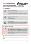
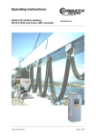
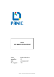
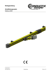
Radio Controls Protean Series P/N 701P0200 2008.09.29 Rev. 4 Protean Radio Controls Manual 1 Conductix Incorporated The technical data and images which appear in this manual are for informational purposes only. NO WARRANTIES, EXPRESS OR IMPLIED, INCLUDING WARRANTIES OF MERCHANTABILITY OR FITNESS FOR A PARTICULAR PURPOSE, ARE CREATED BY THE DESCRIPTIONS AND DEPICTIONS OF THE PRODUCTS SHOWN IN THIS MANUAL. Conductix makes no warranty (and assumes no liability) as to function of equipment or operation of systems built according to customer design or of the ability of any of its products to interface, operate or function with any portions of customer systems not provided by Conductix. Seller agrees to repair or exchange the goods sold hereunder necessitated by reason of defective workmanship and material discovered and reported to Seller within one year after shipment of such goods to Buyer. Except where the nature of the defect is such that it is appropriate, in Seller’s judgment, to effect repairs on site, Seller’s obligation hereunder to remedy defects shall be limited to repairing or replacing (at Seller’s option) FOB point of original shipment by Seller, any part returned to Seller at the risk and cost of Buyer. Defective parts replaced by Seller shall become the property of Seller. Seller shall only be obligated to make such repair or replacement if the goods have been used by Buyer only in service recommended by Seller and altered only as authorized by Seller. Seller is not responsible for defects which arise from improper installation, neglect, or improper use or from normal wear and tear. Additionally, Seller’s obligation shall be limited by the manufacturer’s warranty (and is not further warranted by Seller) for all parts procured from others according to published data, specifications or performance information not designed by or for Seller. Seller further agrees to replace or at Seller’s option to provide a refund of the sales price of any goods that do not conform to applicable specifications or which differ from that agreed to be supplied which non-conformity is discovered and forthwith reported to Seller within thirty (30) days after shipment to the Buyer. Seller’s obligation to replace or refund the purchase price for non-conforming goods shall arise once Buyer returns such goods FOB point of original shipment by Seller at the risk and cost of Buyer. Goods replaced by Seller shall become the property of Seller. There is no guarantee or warranty as to anything made or sold by Seller, or any services performed, except as to title and freedom from encumbrances and, except as herein expressly stated and particularly, and without limiting the foregoing, there is no guarantee or warranty, express or implied, of merchantability or of fitness for any particular purpose or against claim of infringement or the like. Seller makes no warranty (and assumes no liability) as to function of equipment or operation of systems built to Buyer’s design or of the ability of any goods to interface, operate or function with any portions of Buyer’s system not provided by Seller. Seller’s liability on any claim, whether in contract, tort (including negligence), or otherwise, for any loss or damage arising out of, connected with, or resulting from the manufacture, sale, delivery, resale, repair, replacement or use of any products or services shall in no case exceed the price paid for the product or services or any part thereof which give rise to the claim. In no event shall Seller be liable for consequential, special, incidental or other damages, nor shall Seller be liable in respect of personal injury or damage to property not the subject matter hereof unless attributable to gross misconduct of Seller, which shall mean an act or omission by Seller demonstrating reckless disregard of the foreseeable consequences thereof. Seller is not responsible for incorrect choice of models or where products are used in excess of their rated and recommended capacities and design functions or under abnormal conditions. Seller assumes no liability for loss of time, damage or injuries to property or persons resulting from the use of Seller’s products. Buyer shall hold Seller harmless from all liability, claims, suits and expenses in connection with loss or damage resulting from operation of products or utilization of services, respectively, of Seller and shall defend any suit or action which might arise there from in Buyer’s name - provided that Seller shall have the right to elect to defend any such suit or action for the account of Buyer. The foregoing shall be the exclusive remedies of the Buyer and all persons and entitles claiming through the Buyer. 2 Protean RAdio Controls manual P/N 701P0200 2008.09.29 Rev. 4 Index Disclaimer/General Warranty 1.0 Radio Warranty 1.1 Warranty 1.2 Warranty Period 1.3 Warranty Service 1.4 Excluded Parts 1.5 Remarks 2.0 Safety Considerations 2.1 Symbols 2.2 Warnings 3.0 Standard Components 3.1 Receiver (RX) 3.2 Transmitter (TX) 4.0 Installation Procedure 4.1 General Procedure 4.2 Receiver Setup 4.2.1 Power Supply Selection 4.2.2 R0 N.O./N.C. Configuration 4.3 Receiver Installation 4.4 Remote Setting 4.5 Transmitter Setup 5.0 Operation 5.1 General Precautions 5.2 Emergency Procedure 6.0 Basic Troubleshooting and Maintenance 6.1 General Precautions 6.2 General Error Codes and Resolution 6.3 Change of Fuse 6.3.1 Change of Fuse DC Type 6.4 Change of Frequency/Crystal 7.0 Function Settings 8.0 Specifications 8.1 General 8.2 Transmitter 8.3 Receiver P/N 701P0200 2008.09.29 Rev. 4 Protean Radio controls manual 3 1.0 Radio Warranty 1.1 Warranty Conductix-Wampfler guarantees that this equipment meets its published specifications at the time of shipment from the factory. This equipment will perform as described if installed properly. However, Conductix-Wampfler cannot guarantee that operation of remote control system is absolutely errorfree, or without interruption. 1.2 Warranty Period This equipment is warranted against defects in materials and workmanship for a period of one (1) year from the date of shipment. During the warranty period, Conductix-Wampfler is responsible for necessary repairs/ replacement as long as the product can be proven defective. 1.3 Warranty Service For warranty service or repair, this equipment must be returned to Conductix-Wampfler. Customer is responsible for shipping charges to ConductixWampfler. Conductix-Wampfler’s warranty covers only parts and factory labor. No on site in and out charges are covered under this warranty. 1.4 Excluded Parts This warranty does not include consumable parts such as joysticks, batteries, fuses, buttons, and relays. Also, this warranty does not cover defects caused by improper installation, improper/insufficient maintenance, unauthorized modification, improper operation, ignorance of environmental specifications, and/or improper software/interfacing. 1.5 Remarks No other warranty is expressed or implied, except for the above mentioned. The remedies provided herein are the buyers’ sole and exclusive remedies. Conductix-Wampfler shall not be liable for any direct/indirect, special, incidental, or consequential damage. Consult Conductix-Wampfler general warranty for further information. 2.0 Safety Considerations 2.1 Symbols 2.1.1 Safety Considerations: Check input voltage BEFORE wiring this Protean Unit. Insufficient or overvoltage WILL damage unit and VOID Warranty. The default value for AC units is 110v + 10% (99 to 121 VAC). For DC units, the voltage should be 12-24 Volts. This product and related documentation must be reviewed for familiarization with safety markings and instructions before operation. This product requires strict adherence to instructions in order to ensure operational safety. 2.1.2 Safety Symbols The following symbols may be found on the remote control or throughout the remote control documentation. Their purpose is to alert you to potentially dangerous situations. Refer To Manual When the product is marked with this symbol refer to the instruction manual for additional information. High Voltage Indicates presence of hazardous voltage. Unsafe practice could result in severe personal injury. Protective Earth Ground Indicates protective earth terminal 4 Protean RAdio Controls manual P/N 701P0200 2008.09.29 Rev. 4 2.0 Safety Considerations 2.1 Symbols continued Warning Denotes hazard. Included text will give proper instructions. Failure to follow instructions could result in severe personal injury and/or property damage. Caution Denotes hazard. Included text will give proper instructions. Failure to follow instructions could result in minor personal injury and/or property damage. 2.2 Warnings 1. Read this manual carefully before operating and installing this product. 2. Due to the complex nature of equipment, it is necessary to read the entire manual before installation. 3. Only authorized personnel should service this equipment. Unauthorized work on this unit will void the warranty. 4. This manual is for reference only; please call your distributor or Conductix-Wampfler if further assistance is required. 5. The equipment has been tested for correct operation before delivery from the factory. However, it must not be used in critical or hazardous operation where incorrect operation may cause personal injury or equipment damage. 6. After daily operation, please shut off main power in crane and the power to the receiver. 7. Transmitter should be placed in a safe place when not in use to avoid accidental pressing of buttons. 8. The crane should be equipped with mainline contactor, limit switches, and other required safety devices as dictated by CMAA, OSHA, or all other applicable governing regulations. 9. The GND (ground) of receiver must be connected to ground of machine, or electrical shock can occur. 10. Do not use this device during electrical storms or under conditions of electrical interference. 11. Ensure transmitter batteries are in good condition and power for receiver is correct. 12. Installation and maintenance should be done only while the machine’s main power and receiver’s power are off and locked out to prevent electrical shock. 13. Contents of the manual may be amended by the manufacturer without notice. P/N 701P0200 2008.09.29 Rev. 4 Protean Radio controls manual 5 3.0 Standard Components A standard full set of Protean Radio Control consists of: 700PRO4, 700PRO6, 700PRO8, 700PRO6HT and 700PROL8B Kits include a single (1) transmitter 700PRO4D, 700PRO6D, 700PRO8D, 700PRO6DHT and 700PROL8BD Kits include two (2) transmitters. NOTE: Upon receipt of the radio kit, please identify and verify the correct number of transmitters have been included. Model No. Receiver Part No. 700PRO4 701P0040 700PRO4-DC 701P0040-DC 700PRO6 701P0060 700PRO6-DC 701P0060-DC 700PRO6HT 701PROL6B-RX 700PRO6HT-DC 701PROL6BDC-RX 700PRO8 701P0080 700PRO8-DC 701P0080-DC 700PROL8B 701P0080 700PROL8B-DC 701P0080-DC 3.1 Receiver 3.2 Transmitter Style A 6 Style Model Transmitter Part No. A 4 Button 701P0004 B 4 Button HT 701PROL6B-TX A 6 Button 701P0006 B 6 Button L8B 701L8001 A 8 Button 701P0008 Style B Protean RAdio Controls manual P/N 701P0200 2008.09.29 Rev. 4 4.0 Installation Procedures 4.1 General Precautions 1. Observe all safety precautions when climbing or working on the machine. 2. Turn off the main power source of cranes before installation to avoid electric shock. Lockout/Tagout the main power source. 3. Receiver must be installed as to not touch any part of the machine or structure during the operation, except for mounting provisions. 4. The receiver must be fastened securely via shock-proof mount provided. 5. Before installation, inspect the crane’s safety devices and make sure everything is in proper working condition. 6. To avoid any interference, the receiver must be located away from motors, frequency drives, and power cables (shown on page 7). 7. Coil suppressors must be installed on all contactor coils and relay coils where an inductive load may damage the radios relay contacts. Conductix-Wampfler recommends RC type suppressors Conductix-Wampfler Parts 103KVFCC1 with wire leads or 103KVFCC2 with bare metal leads. 4.2 Receiver Preparation 4.2.1 Power Supply There are two types (DC and AC) available for the Protean: DC Type: Input Voltage: 12~24VDC Relay contact: 10A-36VDC AC Type: (4 different transformers: 24/48V, 48/110V, 110/220V, 220/380V): The voltage selection jumper is: Transformer LO HI AC 24/48V 24V 48V AC 48/110V 48V 110V AC 110/220V 110V 220V AC 220/380V 220V 380V 4.2.1 Power Supply Continued 1. Locate the Hi/Low jumper to the lower left of the transformer. 2. Place the jumper connecting the two pins to enable the correct transformer setting as shown in the chart above. NOTE: The Default transformer is the 48/110V version. Please contact your distributor for other options and lead-times. 4.2.2 R0 Open/Closed Setup The Protean series provides two different outputs: NO and NC. The NO is the default setting. If an NC output is necessary, please remove the No. 8 wire (R0/Start) from the connector and insert it into No. 10. Procedure: #8 Pin Remove it Push In P/N 701P0200 2008.09.29 Rev. 4 Protean Radio controls manual 7 4.0 Installation Procedures Procedure Continued Step 3 Step 4 #10 Pin Reconnect it to #10 Pin Lift Up 4.3 Receiver Installation 1. Turn off main power to the machine. 2. Locate a proper place for the receiver. (See diagram below.) a. Select a stable place free from electrical noise, vibration, excessive heat, etc. b. Select a location that is visible from the operation location. c. Select a location at least 3 feet away from motors, relays power cables, and frequency converters. d. Keep away from high voltage wiring and devices. e. The receiver box must be at least 1.5” (4cm) away from other obstacles. 3. Drill four (4) 6mm holes for the receiver mounting the unit with the included hardware. 4. Connect wire to the control circuit of the machine according to the wiring diagram of the receiver (shown in Section 4.3.1). 5. Secure the cable between the receiver and the machine so that the cable sheath will not wear due to vibration. 6. Complete Section 4.5 and test every function of the radio control making sure all motions are correct. 7. Secure the cover making sure not to pinch any wires between the case and the lid. 8. This completes the receiver installation. 8 Protean RAdio Controls manual P/N 701P0200 2008.09.29 Rev. 4 4.0 Installation Procedures 4.3.1 Radio Schematics AC Models 4 Button Protean 6 Button Protean 8 Button Protean & 6 Button L8B P/N 701P0200 2008.09.29 Rev. 4 4 Button Protean HT Protean Radio controls manual 9 4.0 Installation Procedures DC Models 10 4 Button Protean 6 Button Protean 8 Button Protean & 6 Button L8B 4 Button Protean HT Protean RAdio Controls manual P/N 701P0200 2008.09.29 Rev. 4 4.0 Installation Procedures 4.4 Remote Setting Remote setting allows you to pair the new TX and RX if either of them becomes damaged. In order for the radios to work the TX & RX must have the same ID codes and frequency. Using remote setting will set both the TX and RX to have the same ID codes. 4.4.1. Please ensure the following conditions are met before attempting the remote setting procedure. (a) Both TX and RX are of the SAME model and frequency. (c) Turn off the RX power for at least 10 seconds and then turn it on again. (d) Complete the “Remote Setting” within 4 minutes after turning on the RX. The RX will NOT accept the remote setting signal after 4 minutes time has elapsed. (b) Place the transmitter as close as possible to the receiver to avoid any interference. 4.4.2. Remote Setting Instructions: 1. Depress the transmitter STOP or EMS pushbutton. 2. Press DOWN pushbutton and hold it. 3. Press UP pushbutton (4) times and release “STOP or EMS & DOWN” pushbuttons when the red light flashes. 4. Start the system per General Operation (Section 5.0). 1. Press and hold the STOP/EMS pushbutton 2. Press and hold the DOWN pushbutton 3. Press the UP push button 4 times * NOTE: On HT Model (2 speed only depress to first indent for steps 2 & 3) ATTENTION: l In case the remote setting procedure fails, repeat the instructions above within 4 minutes. l The remote setting procedure will update the ID code only. It will not change function settings. l All same model systems on the same frequency will be paired with the transmitters ID code within the operating distance. P/N 701P0200 2008.09.29 Rev. 4 Protean Radio controls manual 11 4.0 Installation Procedures 4.4.3 Remote setting precautions. If a receiver on CH1 and other receivers, for example, on CH2 and CH3 are on the same power line controlled by a switch, such as different hoists on the same crane or rail, special care must be taken. When on CH1 receiver is turned off for the required 10 seconds and then turned on the ID registration, the CH2 and CH3 receivers would be switched on simultaneously and might receive the ID registration signal from the CH1 transmitter. To avoid this, please observe the following: a) The CH2 and CH3 receivers must be at least 20 meters away from the CH1 transmitter it is being used to pair with the CH1 receiver; otherwise the CH2 and CH3 receivers may pair with the CH1 transmitter. In case this happens, switch off the receiver which incorrectly paired for at least 10 seconds, then turn it on again, and use the correct transmitter to pair with it within 4 minutes. Or, switch off the receiver and directly pair the two using the copier to read the data from the correct transmitter and then write to the receiver. Please refer to the “Copier User’s Manual”. On the same power line receiver (CH2) receiver (CH1) The transmitter on CH1 must be at least 20 meters away from receiver on CH2 The CH1 transmitter must be as close to the CH1 receiver as possible. This can exceed 20 meters at some work sites. receiver (CH1) The transmitter on CH1 must be at least 20 meters away from receiver on CH3 transmitter (CH1) b) Because receivers do not accept an ID registration past 4 minutes after application of power to the receiver, or after the MAIN relay is energized, the best way to avoid incorrect programming of other receivers is to press “START” on the CH2 and CH3 transmitters to energize the MAIN relay in the CH2 and CH3 receivers, then use the CH1 transmitter to complete ID code registration within 4 minutes of switching on the receiver. 4.5 Transmitter Setup Two (2) AA sized alkaline batteries are required for the TX. The LED will flash GREEN when the battery power is sufficient. The LED will flash RED when the battery power is low. NOTES: 1. The operating distance will shorten when the batteries are low. 2. Replace with new batteries when battery power is low. 3. Re-chargeable batteries are NOT recommended, use only Alkaline batteries. 12 Protean RAdio Controls manual P/N 701P0200 2008.09.29 Rev. 4 5.0 General Operation 5.1 Standard Operation 1. Turn on the main power switch of the equipment. 2. Install two (2) aa sized alkaline batteries in the transmitter. 3. Press the START/R0 pushbutton or turn the key clockwise to the start position to turn on the main relay inside receiver. 4. Operate normally according to the function settings. 5. Please perform the following procedure when done operating: a. Press STOP or EMS pushbutton. b. Place the transmitter in safe storage location. 6. Turn off the main power switch to the equipment. 5.2 Emergency Operation In case of any emergency please: 1. Press STOP pushbutton or EMS Button on the HT & L8B Models. 2. Switch off the main power of crane. If the problem persists contact your local distributor for service. 6.0 LED Malfunction Alert 6.0 LED MALFUNCTION ALERT 6.1 General Precautions Daily inspection is important and will ensure safe operation. Inspection should include testing the emergency stop and other safety devices and functions. If there is any doubt, operation must be stopped immediately and problems must be corrected before operation is resumed. 6.2 General Error Codes and Resolutions 1. Red LED flashing quickly (every 0.2 sec) when any pushbutton is pressed. Possible Problems: (a) One of the pushbuttons is jammed. (b) The system is not properly powered according to the instructions. *If a problem is found, please contact your local distributor for repair. 2. TX LED flashes slowly (every 0.5 sec). The TX memory is defective. Contact the distributor for repair. 3. RX Error LED flashes slowly (every 0.5 sec). The RX memory is defective. Contact the distributor for repair. NOTE: The receiver error LED is located on the inside of the receiver, observe the appropriate precautions when opening the unit. P/N 701P0200 2008.09.29 Rev. 4 Protean Radio controls manual 13 6.0 LED Malfunction Alert 6.3 Change of Fuse (F1 thru F4) Depress the fuse cover and turn counter-clockwise with a flat screwdriver to open up the fuse cover. Remove the old fuse and insert a new fuse into the cover first. Place this fuse along with cover into the fuse holder base. Depress the fuse cover and turn clockwise with flat screwdriver. Legend: F= Fuse F5 F3 Jumper Wires F2 F1 F4 (AC Type) Relay Board Reference: Relay board shown above is for 700PRO8 (DC Type) Relay Board Reference: Relay board shown above is for 700PRO8-DC 6.3.1 Change of fuse DC Type. 14 Unplug the yellow fuse “F5” (20A) and replace with a new one. Protean RAdio Controls manual Ref Fuse # F1 F2 F3 F4 F5 Size .5A .5A 10A 1.5A 20A Part Number 701C0045 701C0045 701D0032 701D0038 701P0211 P/N 701P0200 2008.09.29 Rev. 4 6.0 LED Malfunction Alert 6.4 Change of Frequency/Crystal The frequency of Protean system can be simply changed by replacing the correspondent crystal frequency in both the TX and RX. Please consult factory for further details. Internal Antenna Crystal Crystal Transmitter Circuit Board (Protean HT & L8 Models) Transmitter Circuit Board (Protean 4, 6, & 8 Button) Crystal Receiver Circuit Board (All Models) 7.0 Function Settings The Protean series offers the following function settings in the transmitter: Normal, ON-OFF, Toggle, and interlocked. By default they are set in an interlocked mode. Protean series radios can be custom programmed at the factory based on requirements and specific applications, please contact your distributor for more information. P/N 701P0200 2008.09.29 Rev. 4 Protean Radio controls manual 15 8.0 Specifications 8.1 General 1. Enclosure: IP65 2. Structure: Glass Fiber/ABS 3. Operating Temperature: -45 ~ +80oC -50 ~ +175oF 4. Relay: 10A/250VAC (AC Power) 15A/12VDC (DC Power) 5. ID Code: 32bit (Greater than 4 Billion unique codes) 6. Hamming distance 7. Static > 15KV 8. Remote ID code setting 9. Operating range: Up to 328 ft (100 meters) 8.2 Transmitter (4, 6 & 8 Button Model) 1. L x W x H: 4.72 x 2.17 x 1.00 in. (120 x 55 x 25 mm) 2. Weight: 5.47 oz. (155g) (with batteries) 3. Uses 2 AA alkaline batteries 4. Low power indicator (LED flash red) 5. Pushbutton jammed detector 6. Shock resistant 7. Output power 4 mW 8. Normal power consumption: 10 mA 9. Sleep mode consumption: 1uA 10. Modulation: FM 8.2 Transmitter for (4 Button HT & 6 Button L8B) 1. L x W x H: 6.42 x 1.93 x 1.77 in. (163 x 49 x 45 mm) 2. Weight: 8.82 oz. (250g) (with batteries) 3. Uses 2 AA alkaline batteries 4. Low power indicator (LED flash red) 5. Pushbutton jammed detector 6. Shock resistant 7. Output power < 4 mW 8. Normal power consumption: 10 mA 9. Sleep mode consumption: < 1uA 10. Modulation: FM 8.3 Receiver 1. L x W x H: 6.34 x 2.91 x 2.05 in. (161 x 74 x 52 mm) 2. Weight: 2.43 lbs. (1.1kg) (w/out cable) 3. AC type: 48/110, 110/220, 220/380VAC DC type: 12V - 24VDC 4. Sensitivity: approx. - 105dBm 5. Shock resistant design 16 6.1 (4) independent common lines (U/D, E/W, S/N, R/O) for 8 Button & L8B Models. 6.2 (3) Independent common lines (U/D, E/W, R/O) for 6 Button Model. 6.3 (2) independent common lines (U/D, R/O) for 4 Button Model. 6.4 (2) independent common lines (U/D, E/W) for HT Models. Protean RAdio Controls manual P/N 701P0200 2008.09.29 Rev. 4 Notes P/N 701P0200 2008.09.29 Rev. 4 Protean Radio controls manual 17 Notes 18 Protean RAdio Controls manual P/N 701P0200 2008.09.29 Rev. 4 Notes P/N 701P0200 2008.09.29 Rev. 4 Protean Radio controls manual 19 www.conductix.com Conductix-Wampfler 10102 F Street Omaha, NE 68127 USA Customer Support Phone: 800 521 4888 Fax: 800 780 8329 Phone: 402 339 9300 Fax: 402 339 9627 [email protected] www.conductix.com 20 Protean Radio Controls Manual P/N 701P0200 2008.09.29 Rev. 4