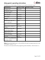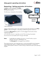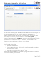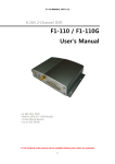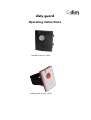
1
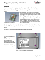
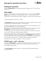
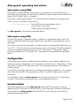
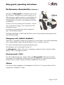
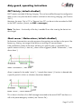
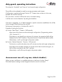
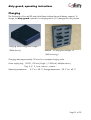
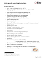
disty-guard
Operating Instructions
Standard version, black
Antibacterial version, white
Table of contents
General....................................................................................................................3
Application................................................................................................................4
ASCOM – Protocol ( DECT location service per SMS )....................................................5
Various ways to wear the tag.......................................................................................6
Putting into operation..................................................................................................7
Subscription...............................................................................................................7
ASCOM system / multi - cell system..........................................................................7
Subscription using PARK......................................................................................8
Subscription using SARI.......................................................................................8
Configuration............................................................................................................8
Unsubscription...........................................................................................................8
Factory setting...........................................................................................................9
Requesting / Setting parameters & Functions...............................................................11
Performance characteristics ( features )........................................................................14
Emergency call ( default: disabled )........................................................................14
Announcement ( Call )...........................................................................................14
Volume................................................................................................................14
DECT Activity ( default: disabled )...........................................................................15
Shock sensor / Motion alarm ( default: disabled )....................................................15
Announcement tone off ( ring tone, default: disabled )...............................................16
Performance characteristics “Hospital” ( default: disabled )........................................17
Call setup ( ASCOM only, with OAPT – interface )....................................................18
Setting through DTMF............................................................................................18
Configuration via microphone ...............................................................................19
Special location request ( default: disabled )..........................................................19
Battery warning as SMS ( ASCOM only, default: disabled ).......................................19
Personal Alarm ( default: disabled )........................................................................19
Special Location Alarm ( ASCOM only, default: disabled )........................................20
Trembler ( OPTION, default: disabled )...................................................................20
Speech Phrase ( OPTION, default: disabled )...........................................................20
SMS - messages ( @ OAPT, 2011-12-05 )...................................................................20
Product approval/ CE mark.......................................................................................20
Charging................................................................................................................21
Operating display....................................................................................................22
Package list.............................................................................................................23
Technical Data.........................................................................................................24
List of functions ........................................................................................................25
disty-guard, operating instructions
General
To maintain an overview over the position of a stranger or staff in a difficult or dangerous
environment at all times, the DECT installation is complemented by a localization function.
This requires a mobile unit disty-guard that is fastened e.g. to the arm or the protective
helmet.
The control center can initiate a request through a
central server in respect of any staff that is equipped
with this device. The server will then establish contact
with the disty-guard; it reports back the current
field strength of the base stations whose signals are
most strongly received and if necessary, additional
information through Beacon service ( ASCOM 9LD
Locator ). The server calculates the position using
such transmitted information and shows it in a layout
Components of the device
plan at the control center.
This Operating Manual is meant for the administrator of the facility who is well informed
about the DECT technology and has the duty of setting and managing this special terminal
device.
The device is supplied in a cardboard box along with a User’s Manual.
The IPEI is indicated on the
label.
The RFID number is
documented with the
manufacturer and can be
requested whenever needed.
The label also fulfills the
function of a warranty seal.
Screw is covered by label = Warranty seal
Page 3 of 25
disty-guard, operating instructions
Application
Components of an ASCOM system
In-built RFID – Tag as identification for passing
through restricted areas or for other
authorization purposes.
Page 4 of 25
disty-guard, operating instructions
ASCOM – Protocol ( DECT location service per SMS )
ASCOM - Beacon - service
Page 5 of 25
disty-guard, operating instructions
Various ways to wear the tag
The disty-guard can be worn or fastened to your body in four different ways.
Possibility 1: Fastening at the wrist:
The two spring bars must be put through the holes of the wrist band and
then inserted into the side holes of the tag as illustrated. Place one side
of the spring bar into the hole and press the other side with your finger
tip so that you will be able to place the opposite top of the spring bar
into the opposite hole.
In case of dismounting press a small stick, like
a paper clip, into the outside of the hole from
the tag so that the spring bar can be removed.
Possibility 2: Fastening with the Clip
As a prerequisite place the two spring bars as illustrated above. Put one side
of the belt clip over one spring bar and than over the other. Please note, that
the hole of the clip is placed at the side of the microphone of the
distyloactor tag.
Possibility 3: Fastening with the Lanyard
Mount the belt clip as described above and connect the snap hook
through the hole of the clip.
Possibility 4: Fastening with the Velcro strap
Thread the strap through the mounted spring bars and attach the
distyloactor tag at your upper arm or helmet as shown in the picture.
Page 6 of 25
disty-guard, operating instructions
Putting into operation
Charge the disty-guard in the disty-guard charger ( Charger station / CS ) until the red
LED turns off.
Subscription
There is an in-built algorithm to accelerate the login process in such a way that the distyguard begins by searching for the strongest base station. It is therefore of paramount
importance to ensure that the terminal device is logged-in in the proximity of a base station!
The preset authentication code ( AC ) is 0000.
The disty-guard is prepared through the following procedure. The process functions only if
the device is not subscribed. See chapter on “Factory setting”.
The device is plugged into the CS. Press the key within the next 5 seconds and wait 10 sec
for the green LED to light up. Now let go off the key.
The function has now been activated. The green LED begins to flash. This indicates that the
disty-guard is searching for the base station that is ready for subscription.
The DECT base station is activated for the subscription process. Ensure that no other base
station / DECT system has activated subscription readiness.
You will hear a “Beep” after successful subscription and the device will restart to accept the
data. The subscription process is thus completed and the disty-guard can be removed
from the charger station. The device begins to search for the base station and register itself.
It switches to the “Stand-by state” ( = idle locked ) after successful synchronization.
The green LED will now flash up briefly once in every 10 seconds.
ASCOM system / multi - cell system
Normally, the disty-guard is subscribed as described in the previous chapter. The system
has already been activated for subscription. The system administrator enters the new
terminal device into the system.
Is the disty-guard required to function in a specific facility? If yes, please follow the
following instructions.
Page 7 of 25
disty-guard, operating instructions
Subscription using PARK
RFPI/ PARI ( = Channel element / Base station ) is the default on which subscription is
performed. This information can be found in ASCOM as System Administrator under DECT/
Radio/ RFPI 9014BC1008 ( <- Example! ).
The process is described as follows. This is performed with the help of the programming
station ( Function ‘set PARK’, manual entry ).
•
c_31_9014_bc10_08
Set the RFPI of the channel element that is
to be used for subscription.
( Please observe hexadecimal entry! )
The disty-guard is subscribed as described above.
Subscription using SARI
In case of big systems ( integrated systems ), affiliation is regulated through a SARI. This
number will be disclosed to the system administrator and the new terminal device set-up in
the system.
The system is activated for subscription; the administrator has disclosed the SARI used ( e.g.
3111111111115 ) and the new terminal device set-up in the system. The SARI is entered in
the device through the programming station ( PS, see chapter on “Requesting / Setting
parameters and functions” ) ( Function 14 ). Subscription is now performed as described
above.
Configuration
Some settings were made in the device during production, which shall be adapted to the
respective purpose of application. For this purpose, see the section on “Requesting / Setting
parameters” as well as “Configuration data”. Factory settings are listed in the chapter on
“Factory setting”.
It is necessary to configure the device accordingly depending on application. This is easiest
when done with the aid of the programming station – a special charging station with PC
connection.
It is advisable to restart the disty-guard after changing parameters. This is done using
Function 3 at the end of the setting process on the programming station.
Unsubscription
The logical disconnection of the disty-guard and the DECT base station is done by
deleting the DECT subscriber in the base station. This process also includes the removal of
relevant data in the disty-guard through the DECT protocol as long as the function is
supported by the base station.
Page 8 of 25
disty-guard, operating instructions
Process: see “Factory setting”.
This is the last step required by the system administrator to delete the subscription data of the
disty-guard from the system and thus unsubscribe the device.
Subscription data are deleted also by resetting to the default status ( Factory setting ).
After a maximum of 3 minutes, the disty-guard switches to the sleeping mode: no LED
lights up, DECT activity is halted.
Factory setting
The following operating procedure is performed to reset to delivery status factory setting
(default), which will work only when the device is subscribed.
•
Set disty-guard to CS. Red LED illuminates as confirmation and acoustic “beep”
signal is heard.
•
Press the alarm key latest after 5 seconds and hold for 10 seconds
•
Green LED illuminates
•
Let go of alarm key before LED switches off ( 2 seconds time )
•
A ( 450 Hz ) tone is heard and red LED illuminates
•
Remove disty-guard from charging station
•
disty-guard switches to power down ( every function switches off )
Page 9 of 25
disty-guard, operating instructions
All values return to basic setting. The device is now ready for subscription again.
Characteristic
Factory setting
Emergency call
Not active
Loudspeaker volume
4
Ring tone volume
2
DECT ACTIVITY
Not active
Shock sensor
Not active
Hospital
Not active
Authentication code ( AC )
0000
Personal setting
( up to eight digits )
PIN
0000
Special location request ( PCnumber )
Not active
Beacon-service ( ASCOM
location device 9dLD )
Not active
Special location alarm
( Beacon-service )
Not active
SMS on low battery
Not active
Ring tone
Active
Personal alarm ( Alarm button
acts as on a ASCOM-Handset
and sends a SMS )
Not active
Note: Alternatively, default status can be established through the programming station ( see
next chapter, Function 5 / 6 ).
The device can be removed from the programming station thereafter ( without function 2. ).
Page 10 of 25
disty-guard, operating instructions
Requesting / Setting parameters & Functions
Parameters can be configured in the distyguard using the programming station that can
be ordered as accessory.
PC
The following is a description of the handling.
USB
PS
12VDC/
150mA
Programming station
With the Single Charging station with programming function (PS), the battery of the distyguard can either be charged or some settings modified through data transmission.
To charge the disty-guard using the PS, it must be plugged into the station without
entering a command.
A PC with USB connection is required to use the PS for the setting of parameters.
The PS will now be connected to the PC through a USB cable.
Note:
If applicable, the installation of a driver ( = Virtual Com-Port ) may be
required ( CDC driver, USBLadestation.inf ).
The disty-guard is not plugged during installation.
The programming tool ( ‘disty Programmer App’ ) can be downloaded from the homepage
of the company Disty. Save it in a folder of your choice and activate it. A window will
appear with the question: Execute or Cancel. Clicking on Execute will open up the operating
program.
Page 11 of 25
disty-guard, operating instructions
The App has the sheet “PC-COM” selected. This is the default after start of the program. On
this sheet the appropriate COM port should be selected via the drop-down list.
With the upper left button the APP starts into programming mode. The lower line, which
shows the hint and/ or status gives the command to insert the disty-guard.
After the PS has recognized the disty-guard, the communication begins ( the LEDs of the
tag will blink ). The status line will light up in green color. The tool is ready for use!
Now you can choose the function or value you want to change.
As an Example: alarm number:
•
go to sheet 'Configuration 1'
•
write the appropriate number, which shall be dialed by pressing the alarm button,
into the field 'Alarm number'
•
initiate the transmission by clicking the 'write' button
Now the LEDs again start blinking to indicate the ongoing communication. At the end of
transmission we see the green status line.
Page 12 of 25
disty-guard, operating instructions
In this way several parameters can be set to your needs.
In the end you stop the mode by pressing the upper left button.
The PS can be used as charging station. Therefore, no PC connection is needed.
The disty-guard is plugged in and out as usual.
Page 13 of 25
disty-guard, operating instructions
Performance characteristics
( features )
Basically, the disty-guard is conceived in such a way
that an event is transmitted to a central instance as an
SMS message or speech connection is established with
a preset number. Both actions can also be combined.
This depends on one hand, on the application and the
infrastructure.
An event in this sense means press the button, insertion
into/ remove from charger or an incident due to the
acceleration sensor.
For setting or activation through ‘disty Programmer
App’, see preceding chapter.
Exchange of messages via SMS and the Beacon service are possible only during operation
with ASCOM facilities.
Emergency call ( default: disabled )
If the button is pressed for longer than 3 seconds in a normal state, a link will be established
with a programmed number; the red LED flashes. That is a speech connection.
This can be terminated only by pressing the button again.
The emergency call is set through Function 10.
If a disty-guard is called, which has no emergency number set, then it stores the callers
identity ( CLIP ) as emergency number.
Announcement ( Call )
If a call is made through any random number, the disty-guard builds-up the connection
immediately. The loudspeaker and the green LED are switched on and a brief tone informs
the bearer that an audio connection has been established with the caller.
Volume
The volume of the loudspeaker can be adapted to Function 19 in 5 steps while that of the
ringing tone is adapted in 2 steps
Page 14 of 25
disty-guard, operating instructions
DECT Activity ( default: disabled )
DECT remains switched off during charging. This can be modified through the configuration
data in such a way that the device remains switched on also during charging ( see Function
24.2 )
Moreover, the event “Set in CS” or “Remove from CS” can be set to be transmitted as SMS
to the OAPT interface ( format, see SMS – messages ).
Note: The alarm – functionality of the key is enabled 5 sec after inserting the device into
the charger!
Shock sensor / Motion alarm ( default: disabled )
Performance characteristics serve the purpose of recognizing an accident on the part of the
bearer e.g. fainting, non-usage of the device or touching of a secured object.
If the acceleration values of the sensor fall short of a specific value ( = threshold ) for a
specific amount of time ( = time out ), alarm will be triggered ( Mode “Quiescence” / ‘man
down alarm’ )
Mode “Quiescence” / man down
Alarm is reported in the mode “active” ( / ‘moved after timeout’ ) if motion is detected after
a specific period in which no vibrations have been detected.
Mode “Active” / motion detection
This is done in the form of an SMS message transmitted to the central OAPT interface as a
call to the preset emergency number ( see Function 24 ).
Page 15 of 25
disty-guard, operating instructions
The values for “threshold” and “time out” can be set through configuration.
The profile can be adapted to needs by varying parameters and timeout.
Configuration is performed through Function 21. Timeout time can be set in this case,
between 20 and 254 seconds.
The ‘man down’ variation will then be active in the basic setting.
It will be set to ‘motion detection’ by setting the checkbox.
If an event is triggered, i.e. an SMS transmitted / speech connection established, this will be
shown through a brief flashing of the red LED.
Performance characteristic is switched off in the CS.
Examples of setting the functions:
a) Function “Man Down”, Timeout = 240 seconds
Alarm time of 4 minutes must be set through configuration ( Programming station
( PS ): Function 21 ).
If the device is not moved for a minimum of 4 minutes, the respective SMS will be
displayed at the OAPT interface. The precise format is listed further behind ( MD ).
Alternatively, a call is put through to the preset number.
b) Function “Motion Detection”, Timeout = 180 seconds.
The function as well as the alarm time of 3 minutes must be set through configuration.
If the device has not been moved for 3 minutes and is then moved once again, an
SMS will be transmitted to the OAPT interface.
Alternatively, a call will be put through to the preset number.
Announcement tone off ( ring tone, default: disabled )
When you get a call there is an audible indication in the form of a short "beep".
The locator options setting can be changed so that this sound is not heard.
Page 16 of 25
disty-guard, operating instructions
Performance characteristics “Hospital” ( default: disabled )
The feature is described as follows:
Alarm case
•
Patient presses button→ disty-guard is switched on for at least 10 minutes and
dispatches a SMS message (→ Alarm & Coordinates, depending on configuration )
•
Patient receives visual and acoustic feedback
•
Nurse is informed through her handset and can gets back to patient
•
After 10 minutes, the device switches off again and is ready for new alarm
The following parameters are used as setting:
•
Emergency number ( -> Function 10 )
•
Locator options → Function 24.3.
Page 17 of 25
disty-guard, operating instructions
Call setup ( ASCOM only, with OAPT – interface )
Call setup SMS: if a SMS with the content (PTP)CS;A=12345;S=0 is sent to the distyguard, it calls the subsciber 12345.
With an additional parameter only the microphone is enabled. No optic/ acoustic
indication will be observed at the disty-guard, when a SMS with this parameter setting is
sent. Please use with caution!
•
(PTP)CS;A=12345;S=0 -> normal
•
(PTP)CS;A=12345;S=1 -> silent ( microphone only )
Setting through DTMF
Different parameters can be alternatively set with the help of the DTMF technology. Speech
contact is first established with the disty-guard for this purpose and the remote subscriber
sends the respective sign.
After recognizing the desired setting, in this case the introductory sign ‘**9’, a one-minute
countdown begins for the modification of the desired parameter.
Following successful programming, a positive acknowledgment tone will sound and the
connection will be terminated.
Only one parameter can be modified.
•
Authentication Code ( AC ) '* * 9 pin 5 <ac> #'
( ac = 0..9, 4-/ 8- digits )
•
Volume of loudspeaker
'* * 9 pin 1 <Volume value> #'
( Volume value = 1 .. 5 )
•
Volume of ringing tone
'* * 9 pin 4 <Volume value> #'
( Volume value = 1..2 )
•
Emergency call number
'* * 9 pin 2 <Calling number>1 #'
( Calling number max. 20 digits )
•
Shock sensor2
'* * 9 pin 3 <Value> #'
( Value = 0: Off,
1: Man down alarm,
2: Moved after timeout )
pin: 4 digits. Required only if it is not 0000.
1 1st number = * → internal, = # → external number
2 Timeout = 2 minutes
Page 18 of 25
disty-guard, operating instructions
To avoid disturbing noises during transmission, it is advisable to switch off the microphone of
the transmitting device.
Configuration via microphone
To configure a disty-guard without programming station, it is possible to adjust the
parameter sent by DTMF tones through the microphone. This may be necessary if the base
station uses an AC, which differs from the default setting.
As a prerequisite the disty-guard must be unsubscribed.
The function is activated by pressing the alarm button. Both LEDs are illuminated.
Now the device will record the DTMF-tones via the microphone for the next 30 seconds.
For example, the setting of an AC = 0627 would be as follows: ** 9 5 0 6 2 7 #.
To generate those sounds, there are various possibilities. This can be done with a tone
generator, a telephone, mobile phone or a PC - program. In the case of a telephone a
connection is made to any subscriber. Then place the disty-guard near the earpiece or
speaker of the phone, push the button on the disty-guard and now select the abovedescribed combinations of numbers on the push button at the telephone.
The successful programming is indicated by a positive acknowledgment tone.
If you want to change other parameters, this procedure must be repeated accordingly.
Special location request ( default: disabled )
For certain pabx, the current location of the user/ terminal is determined by a short call. This
process is carried out periodically by a PC.
Not to disturb the normal operation, the caller's number ( CLIP ) is compared to a
programmed one. In case the call comes from the PC, the connection will be released
immediately. The use informed about this process through the brief flash of the green LED.
Battery warning as SMS ( ASCOM only, default: disabled )
If the battery reaches its low limit of capacity, a corresponding text message is sent to the
control panel ( format, see SMS – messages ).
Personal Alarm ( default: disabled )
If this feature is enabled ( locator options → Function 24.6. ), the function of the key is
changed. The disty-guard responds as the alarm button at a ASCOM - handset:
long press → 'Test - alarm', two short pressures → 'User - alarm'.
The messages of the alarm button and the shock sensor will be transmitted as SMS Page 19 of 25
disty-guard, operating instructions
message.
For more details on the protocol, please refer to the german version of this document!
Special Location Alarm ( ASCOM only, default: disabled )
Works together with ASCOM locator device 9dLD. Sends an alarm, when it detects such
beacon.
Trembler ( OPTION, default: disabled )
Push the button to get a picture how it feels to have this option ( DEMO! ).
Speech Phrase ( OPTION, default: disabled )
The peer partner hears a speech phrase, like “123 man down” at the beginning of a call, if
the shocksensor is enabled and the situation of 'man down' was raised.
SMS - messages ( @ OAPT, 2011-12-05 )
For an complete overview of the implemented protocol, please refer to the documents
•
SSD – Ascom IP-DECT concept (B).pdf
•
SSG-Bedienungsanleitung.pdf
Product approval/ CE mark
Disty communications GmbH hereby declares that the disty-guard conforms to the
fundamental requirements and other relevant regulations stated in Directive 1999/5/EU
( Radio and Telecommunication Terminal Equipment, R&TTE ). Conformity is declared by the
CE mark.
The full declaration of conformity can be viewed on our website: http://www.disty.de.
Page 20 of 25
disty-guard, operating instructions
Charging
The illumination of the red LED and a brief beep indicate the end of battery capacity. To
charge, the disty-guard is placed in a charging device ( CS ) designed for this purpose.
Charging station disty-guard charger 1
( Table device )
Multiple – CS disty-guard charger 10
( Wall mounting )
Charging takes approximately 12 hours for a complete charging cycle.
Power supply plug: 12 VDC, 150 mA ( Single - ), 1500 mA ( Multiple station ),
Plug: 5,5 * 2,1 mm, interior +, exterior Operating temperature:
0 °C to + 40 °C; Storage temperature: - 20 °C to + 60 °C
Page 21 of 25
disty-guard, operating instructions
Operating display
Operating status can be read on the LEDs.
Mode
LEDs / Acoustic
1
Plug into charging station
“Beep” tone, red LED illuminates once
2
Remove from charging station Abort charging: red LED goes off
3
Charging ( DECT activity on )3 Red LED flashes during charging and turns off when
charging is completed
( Flash rhythm: every second )
Green LED as in 6) / 7) / 8)
4
Charging ( DECT activity off ) Red LED flashes during charging and turns off when
charging is completed
( Flash rhythm: every second )
Green LED is off
5
Charge status low
Red LED flashes once in every 30 seconds and beep
tone4
6
Subscribed, registered
Green LED flashes once in every 10 seconds
7
Subscribed, out of range /
searching for base station
Red LED flashes every second
8
DECT connection
Green LED is switched on
9
Alarm
Red LED flashes once in every 0.5 seconds
10 Range ( Limit )
Red LED flashes fast. Warning tone
11 Status on delivery (Default),
Press of button
Red and green LED on
12 Programming through DTMF
Green LED flashes
It is fixed in factory settings that DECT activity turns off when the disty-guard is in the CS.
If the device is configured in such a way that DECT operation is continuously active, the
meaning of the green LED during charging as stated in the above table will be maintained.
Moreover, the respective SMS is then sent to the control center while plugging into the CS or
removing from the CS.
If DECT activity is off, DECT operation will be stopped during charging. Moreover, no SMS
will be sent as described above.
3 depending on setting
4 Tone stops after 5 min.
Page 22 of 25
disty-guard, operating instructions
The LEDs have a different meaning if operated on a programming station.
Mode
LEDs
Device is plugged in the programming
station and is ready for data
transmission
Green and red LED illuminate
Data transmission
Green LED illuminates, red LED flashes => Data
received / Red LED illuminates, green LED flashes
=> Transmitting data5
Charging voltage too low / PS is in
data transfer mode
Green and red LED flash together for 3 seconds
Package list
The following items will be found together with the disty-guard in the box.
•
disty-guard
•
two spring bars
•
Strap for the upper arm with Velcro
•
Belt clip
•
Lanyard
•
Wristband
•
Operating manual
•
Carton
•
Charging - / Programming station, incl. Power supply & USB - cable ( optional )
5 After sending 20 symbols only the blinking LED will be on.
Page 23 of 25
disty-guard, operating instructions
Technical Data
•
DECT – GAP, EN 300 444 ( EU -/ US - DECT )
•
Plastic housing, 75 mm x 60 mm x 16 mm, curved, edges rounded
with radius = 2 mm
•
Shock protection through circumferential intermediate ring
( Housing dimension above all 75 mm x 68 mm x 16 mm )
•
Fastening using belt strap through two lateral eyelets
( Sizes: 28 mm x 2.5 mm ) Belt clip or arm band
•
Dialing number field is dimensioned at 15 mm x 8 mm
•
Weight is approximately 66 g
•
Protection class IP 65
•
Operating6: > 120 hrs., Position request: once every 15 minutes, no activated
Beacon – Service
•
Talk time: up to six hours
•
Charging/ Programming method: inductive
•
information transmission through SMS7
•
Motion sensor
•
Loudspeaker for acoustic signaling or speech output
•
Button for emergency call and operation
•
LEDs for operative display ( 2 colors )
•
Sealing / Abutting edge / Button: material in soft plastic
•
Microphone
•
Lithium ion battery, Capacity: 450 mAh, 3,7 V,
Charging time: about 12 hrs. for a complete charging cycle
•
Operating temperature: - 10 °C bis + 40 °C8; Storage temp.: - 10 °C bis + 60 °C
•
Black or white housing ( antibacterial )
•
Integration of a RFID-Tag for EM4102 ( Key-Fob in 125 kHz technology )
•
More information: www.disty.eu
6 at optimal temperature: + 20 °C
7 usage results in higher power consumption
8 charging operation up to a max. + 35 °C!
Page 24 of 25
disty-guard, operating instructions
List of functions
The following is a table containing all relevant functions that are required for the setting of
the disty-guard. The PS will be required for this purpose ( see chapter on “Requesting /
Setting parameters and functions” ).
Ser. Nr.
Name
Command
Parameter
1
start connection
c 3
2
stopp connection
c 4
3
reset disty-guard
c 900
4
reset PS
c 9
5
factory reset
c 126 d 0 0
6
factory reset, params only
c 126 d 1 0
7
read authentication code
c 67 34
8
set authentication code
c 66 34 ffff 0000
9
read alarm number
c 6a
10.1 set alarm number, extern
c 69 dfff ffff ffff ffff ffff ffff ffff ffff
10.2 set alarm number, intern
c 69 cfff ffff ffff ffff ffff ffff ffff ffff
10.3 set alarm number, SIP-pabx
c 69 dccf ffff ffff ffff ffff ffff ffff ffff
11
read firmware revision
c 1b
12
read configuration revision
c 1c
13
read SARI
c 128
14
set SARI
c 127 0 ffff ffff
15
read PLI/ LAL/ ZAP
c 36
16
read PARK
c 32
17
read IPEI
c 34
18
read volume
c 67 33
19
set volume ( 4, 2 )
c 66 33 3 1
20
read shocksensor
c 67 27
21
set shocksensor ( 120 s )
c 66 27 1 78
22
read range alarm
c 67 2b
23
read locator options
c 67 3a
24.1
set locator option
c 66 3a 1 0
24.2
set locator option
c 66 3a 2 0
24.3
set locator option
c 66 3a 4 0
24.4
set locator option
c 66 3a 8 0
24.5
set locator option
c 66 3a 10 0
24.6
set locator option
c 66 3a 208 0
25
read PIN
c 67 0
26
set PIN
c 66 0000 ffff
27 ( = 16 ) read PARK
c 32
28
set PARK
c 31 ffff ffff ff
29 ( = 15 ) read PLI
c 36
30.1
set PLI
c 35 0 ff
30.2
set LAL
c 35 1 ff
30.3
set ZAP
c 35 2 1f
30.4
set PARK empty
c 35 3 1
30.5
set subscription record empty c 35 4 1
40
set debug off
c 1 0
41
set debug on
c 1 4
42
show status
c 129
43
show battery voltage9
c 123 1
44
set PC number
c 6E ffff ffff ffff ffff ffff ffff ffff ffff ffff
44
read PC number
c 6F
24.1, 24.2, 24.3: combination possible
24.4, 24.5: alternative
9 Output semi-decimal, 4.9 mV/ step
Page 25 of 25
Tel: +49 (0)4 31/3 64 58-00
Operating instructions disty-guard
http://www.disty.eu
All rights to changes reserved!
disty communications gmbh
Holzkoppelweg 14
D - 24118 Kiel
Version 9.4
Germany
Edition 07/ 2013