1
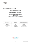
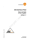
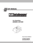
Operating instructions
7390884/00 04/2014
AS-i Profibus gateway
AC1411 / AC1412
UK
Contents
1 Preliminary note���������������������������������������������������������������������������������������������������4
1.1 Notes on this document���������������������������������������������������������������������������������4
1.2 Symbols used������������������������������������������������������������������������������������������������4
2 Safety instructions�����������������������������������������������������������������������������������������������4
2.1 General����������������������������������������������������������������������������������������������������������4
2.2 Installation and connection����������������������������������������������������������������������������4
2.3 Tampering with the device�����������������������������������������������������������������������������5
3 Functions and features����������������������������������������������������������������������������������������5
3.1 Configuration interface X3�����������������������������������������������������������������������������5
3.2 Fieldbus interface X6�������������������������������������������������������������������������������������5
3.3 Electrical supply���������������������������������������������������������������������������������������������6
4 Installation�����������������������������������������������������������������������������������������������������������6
5 Electrical connection��������������������������������������������������������������������������������������������6
5.1 Device supply �����������������������������������������������������������������������������������������������6
5.1.1 Device supply via AUX, AS-i supply via AS-i power supply������������������6
5.1.2 Device and AS-i supply via the AS-i power supply�������������������������������7
5.1.3 Device and AS-i supply via one common power supply�����������������������7
5.2 Wiring������������������������������������������������������������������������������������������������������������8
6 Operating and display elements��������������������������������������������������������������������������9
6.1 Operating elements���������������������������������������������������������������������������������������9
6.2 LED indicators���������������������������������������������������������������������������������������������10
6.2.1 Device LED H1�����������������������������������������������������������������������������������10
7 Operation�����������������������������������������������������������������������������������������������������������10
7.1 Settings��������������������������������������������������������������������������������������������������������10
7.1.1 Language selection����������������������������������������������������������������������������10
7.2 Navigaton���������������������������������������������������������������������������������������������������� 11
7.2.1 Navigation elements��������������������������������������������������������������������������� 11
7.2.2 Pictograms and main navigation��������������������������������������������������������12
8 Diagnostics��������������������������������������������������������������������������������������������������������13
9 Technical data����������������������������������������������������������������������������������������������������13
9.1 Data sheets�������������������������������������������������������������������������������������������������13
9.2 Programming manual����������������������������������������������������������������������������������13
2
10 Maintenance, repair and disposal��������������������������������������������������������������������13
11 Approvals / standards��������������������������������������������������������������������������������������14
12 Scale drawing��������������������������������������������������������������������������������������������������14
UK
3
1 Preliminary note
1.1 Notes on this document
This document applies to devices of the type "AS-i Profibus gateway"
(art. no.: AC1411 / AC1412).
It is part of the device and contains information about the correct handling of the
product.
This document is intended for qualified electricians. These specialists are people
who are qualified by their training and their experience to see and to avoid
possible hazards that may be caused during operation of the device.
►► Read this document before using the device.
►► Keep this document during the service life of the device.
1.2 Symbols used
►
>
[…]
→
Instructions
Reaction, result
Designation of pushbuttons, buttons or indications
Cross-reference
Important note
Non-compliance can result in malfunction or interference.
Information
Supplementary note
2 Safety instructions
2.1 General
►► Observe these operating instructions.
►► Adhere to the warning notes on the product.
Non-observance of the instructions, operation which is not in accordance with use
as prescribed below, wrong installation or incorrect handling can affect the safety
of operators and machinery.
2.2 Installation and connection
The device must only be installed, connected and put into operation by a qualified
electrician as the safe function of the device and machinery is only guaranteed
when installation is correctly carried out.
4
The installation and connection must comply with the applicable national and
international standards. Responsibility lies with the person installing the device.
This is a class A product. The device may cause radio interference in
domestic areas. In this case it can be necessary for the user to take
appropriate measures.
2.3 Tampering with the device
Tampering with the device is not allowed and will lead to an exclusion of liability
and warranty. Tampering with the device can affect the safety of operators and
machinery.
►► Do not open the device.
►► Do not insert any objects into the device.
►► Prevent metal foreign bodies from penetrating.
UK
3 Functions and features
The AS-i Profibus gateway integrates one (AC1411) or two (AC1412) AS-i
masters, a WEB server and a Profibus interface with a 9-pole D-Sub socket.
• It controls the exchange of data to the sensor / actuator level.
• It communicates with the superior control level via Profibus.
• It visualises sensor / actuator data on the integrated WEB server.
• It allows device configuration via the WEB server.
3.1 Configuration interface X3
• 10 Mbps and 100 Mbps
• TCP / IP - Transport Control Protocol / Internet Protocol
• UDP - User Datagram Protocol
• IT functionality: HTTP server
• RJ45, Twisted-Pair
3.2 Fieldbus interface X6
• Profibus DP (DPV0 / DPV1)
• 9.6 kbaud to 12 Mbaud
5
3.3 Electrical supply
• The device can be supplied either from 24 V (AUX) or from AS-i
• AS-i power 24 V compatible
4 Installation
►► Fix the AS-i Profibus gateway onto a 35 mm raised rail.
The protection rating of the device is IP 20, therefore it should be mounted in a
protected location (e.g. control cabinet).
Ensure a condensation-free environment. Avoid excessive dust, vibration
and shock. The air circulation through the vents must not be impeded.
Avoid installation in direct vicinity of frequency inverters or other interfering
sources.
5 Electrical connection
The device must be connected by a qualified electrician.
►► Disconnect power before connecting the device.
►► Observe the national and international regulations for the installation of
electrical equipment.
►► Connect the device as indicated on the terminals.
►► Ensure an electrical connection between the AS-i Profibus gateway
(terminal FE) and the ground of the installation.
►► Only insert or remove the AUX jumper when the device is disconnected.
Otherwise, a device failure may occur.
5.1 Device supply
To operate an AS-i system, an AS-i power supply (e.g. AC1236) or the
data decoupling module AC1250 (not supplied) with a DC power supply is
required.
►► Supply the device with one of the following versions.
5.1.1 Device supply via AUX, AS-i supply via AS-i power supply
►► Supply the device with a voltage of 24 V DC (18...32 V PELV) (e.g. from the
24 V DN3011 power supply of ifm electronic). The connection is made to the
terminals X2.
6
►► Pull out the AUX jumper.
►► To supply the AS-i lines, connect the terminals X1 to one or two AS-i power
supplies (AC1411: one AS-i master, AC1412: two AS-i masters).
►► Ensure a low-resistance connection of the symmetry point of the device
(terminal X1.5 FE) to the ground of the installation.
5.1.2 Device and AS-i supply via the AS-i power supply
►► To supply the AS-i lines, connect the terminals X1 to one or two AS-i power
supplies (AC1411: one AS-i master, AC1412: two AS-i masters).
►► Ensure a low-resistance connection of the symmetry point of the device
(terminal X1.5 FE) to the ground of the installation.
UK
The AUX jumper is plugged onto the connector X2 (factory setting), the
device is supplied via AS-i line 1 (X1.3 and S1.4).
5.1.3 Device and AS-i supply via one common power supply
►► Plug the data decoupling module AC1250 (not supplied) into the terminals X1
and X2 to supply the device and the connected AS-i lines.
AC141x
AC1250
7
►► Ensure a low-resistance connection of the data decoupling (terminal "FE") to
the ground of the installation.
The gateway and both AS-i lines are supplied via one power supply
(PELV 21.5 V...31.6 V AS-i or AUX). The AS-i lines have a thermal short-circuit
protection (4 A).
Several gateways can be supplied by one powerful power supply.
5.2 Wiring
8
Terminal X1 Combicon
Pin
Designation
AS-i 2 +
1
AS-i + for AS-i line 2
AS-i 2 -
2
AS-i - for AS-i line 2
AS-i 1 +
3
AS-i + for AS-i line 1
AS-i 1 -
4
AS-i - for AS-i line 1
FE
5
Functional earth
Terminal X2 Combicon
or AUX jumper
Pin
Designation
24 V
1
+24 V device supply
0V
2
0 V device supply
Terminal X3 RJ 45
Configuration interface
Terminal X6 D-Sub 9
Profibus interface
6 Operating and display elements
6.1 Operating elements
UK
1:
2:
3:
4:
5:
6:
7:
8:
9:
Profibus interface (D-Sub 9) X6
Device LEDs H1 green / yellow / red
Softkeys
Navigation buttons
Combicon connector X1
AUX jumper X2
Front flap
Slot for SD card
Configuration interface X3 (RJ45)
9
6.2 LED indicators
6.2.1 Device LED H1
A diagnostic LED on the AS-i Profibus gateway informs you of the state of the
device and the connected systems.
LED status
The green LED is lit:
Yellow LED flashes slowly (0.5 Hz):
Red LED flashes quickly (2 Hz):
Description
>> Device has been started.
>> There is no warning message.
>> There is no error message.
>> There is a warning message.
>> There is no error message.
>> There is an error message.
7 Operation
7.1 Settings
During operation the display is switched off after 10 minutes without
operation.
►► Activate the display by pressing any desired button.
7.1.1 Language selection
►► Change the user language of the device by pressing the ► button and the ▲
button or ▼ button simultaneously.
10
7.2 Navigaton
7.2.1 Navigation elements
xxx
#
UK
xxx
1:
2:
3:
4:
5:
6:
7:
8:
xxx
User level
Focus
Operating area
Softkey labelling
Navigation compass
Navigation status bar
Main navigation bar
Info bar
11
7.2.2 Pictograms and main navigation
Quick setup (summary of the menu points required for a basic
configuration)
•Project all
Projection adaptation for AS-i master 1 and AS-i master 2 (only AC1412)
•Operating mode
Selection of the operating modes for
-- AS-i master 1,
-- AS-i master 2 (only AC1412),
-- System (gateway, manual)
•Fieldbus
-- Display / modify the parameters of the Profibus interface
-- Profibus address
•Configuration interface
-- Display / modify the parameters of the Ethernet configuration interface
-- DHCP
-- IP address
-- Subnet mask
-- Gateway address
•Addressing 1
-- Slave overview AS-i line 1 (with the option to change AS-i addresses)
•Addressing 2
-- Slave overview AS-i line 2 (with the option to change AS-i addresses)
AS-i 1
•AS-i master settings
•AS-i diagnosis
•AS-i slaves
AS-i 2
•AS-i master settings
•AS-i diagnosis
•AS-i slaves
System
•Information
•Settings
•Diagnostics
12
Interfaces
•Settings and information of the configuration interface
•Settings and information of the Profibus interface
Further details see programming manual → chapter 9.2
8 Diagnostics
Any warning or error message is indicated in the display of the device. The
UK
pictogram of the function unit concerned is superposed by a warning or error
symbol. If for one function unit a warning and an error message exist at the same
time, only the error symbol is displayed.
Warning message
Error message
9 Technical data
9.1 Data sheets
Data sheets can be found at:
www.ifm.com → data sheet search → AC1411 / AC1412
9.2 Programming manual
The programming manual can be found at:
www.ifm.com →data sheet search → AC1411 / AC1412
→ Operating instructions
10 Maintenance, repair and disposal
►► Replace the buffer battery of the real-time clock as required, type CR2032.
►► Dispose of the device in accordance with the national environmental
regulations.
13
11 Approvals / standards
The EC declaration of conformity and approvals can be found at:
www.ifm.com → data sheet search → AC1411 / AC1412 → Approvals
12 Scale drawing
106,2
128,2
135,5
93
14
UK
15