1
U
SER MANUAL
DATALOGGER
TM
For Controllers
6035666 & 6073993
AC1754.eps
Manual Number 6075865-R4
cascade
corporation
Cascade is a Registered Trademark of Cascade Corporation
C
ONTENTS
Page
INTRODUCTION, Section 1
Introduction
Special Definitions
INSTALLATION, Section 2
Hardware
Hardware Installation
AFC Retrofit Installation
Wiring Connections
Software
Software Installation
Uninstall Software
Network Settings
AFC Controller Setup
USING AFC DATALOGGER HARDWARE, Section 3
Collecting Clamp Force Data
AFC Datalogger LED
USING AFC DATALOGGER SOFTWARE, Section 4
Opening AFC Datalogger Software
Navigating through the Software
Downloading Data
Card Reader Method
Ethernet Method
Creating Reports – Reports Tab
Event Log
Equipment List
Download Log
Export Reports to Excel
Setup Tab
Add A Truck Description
Set Log Time
Maintenance Tab
Data Backup
TROUBLESHOOTING, Section 5
Troubleshooting
No Data in Report
To Clear 4 Rapid Flashes
PARTS, Section 6
AFC Datalogger Parts
AFC Datalogger Retrofit Kit Parts
i
1
1
2
2
3
3
4
4
6
7
8
9
9
10
10
11
11
13
14
14
15
15
15
16
16
17
17
17
19
19
20
21
23
6075865-R4
I
1.1
NTRODUCTION
Introduction
This manual is for the Cascade AFC Datalogger. Contents
include Installation, Using AFC Datalogger Hardware,
Using AFC Datalogger Software, Troubleshooting and
Parts.
When the AFC Clamp Ready light is on and the clamp
opens, data is collected and logged by the AFC
Datalogger.
IMPORTANT: Proper operation must be verified after
installation and setup by recording and reporting test
clamp force data.
NOTE: If SD (Secure Digital) Card is replaced, limit size to
1 gigabyte. Make sure card is SD media and not SD HD
media.
Da
g
log
ta
u
tN
ar
t P er,
Ki
r:
be
m
86
75
60
3
ce
vi
De
r
Pa
r:
be
um
tN
86
75
60
3
TM
AC1393.eps
1.2
Special Definitions
The statements shown appear throughout this Manual
where special emphasis is required. Read all WARNINGS
and CAUTIONS before proceeding with any work.
Statements labeled IMPORTANT and NOTE are provided
as additional information of special significance or to make
your job easier.
WARNING - A statement preceded by
WARNING is information that should be
acted upon to prevent bodily injury. A
WARNING is always inside a ruled box.
CAUTION - A statement preceded by CAUTION is
information that should be acted upon to prevent
machine damage.
IMPORTANT - A statement preceded by IMPORTANT is
information that possesses special significance.
NOTE - A statement preceded by NOTE is information that
is handy to know and may make your job easier.
6075865-R4
1
I
NSTALLATION
2.1
Hardware
2.1-1
Hardware Installation
40-Pin Connector (Black)
IMPORTANT: Hardware installation should only be
performed by skilled personnel. Failure to install
equipment properly will compromise operation of the AFC
Datalogger.
To AFC
Components
AFC Controller
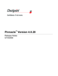
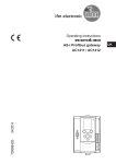
Use the schematic below to connect the AFC Datalogger
to the AFC system.
Main Cable
Harness
AFC Cable
No. 228139
Ethernet
Cable
AFC
Datalogger
Cross-over
Ethernet
Cable
Host
Computer
Ethernet
Connector
3
LED
AC1394.eps
12-Pin Connector (Gray)
4
2
12 Pin
Datalogger
Connector
To AFC
Components
C1
(Controller
Input)
12 Pin Cable
Assembly
SI
(Scanner Input)
NOTE: Scanner Input is
an optional connection for
obtaining bar codes.
If configured with Scanner
Input option, contact
Cascade.
AFC Datalogger
Components
5
4
Connect to
Power Bus
+ –
–
(Next Available +
Circuit)
CN1
(CAN Interface
Input)
CAN
Controller
Next
Available
Circuit
1 Mount the AFC Datalogger in a location
where the SD Card access door (see
image on page 11) and ethernet cable
can be easily accessed.
2 Connect the 12 Pin Cable Assembly to the 12 Pin
Datalogger connector.
Power Bus/ Relay
Unswitched
-+ +-
To AFC Controller
Components
Unswitched
NOTE: Refer to section 2.1-3 for connector details.
Unswitched
Switched
3 Mount the LED in a location where the operator can
view AFC Datalogger activity easily. Assemble LED
wires, connector and wedge. The black wire (wire 2)
to Pin 2 and white wire (wire 1) to Pin 1. Connect LED
wires to the 12 Pin Cable Assembly.
Ground
Truck
Fuse Block
Key
4 For Standard AFC, connect the C1 Cable to the AFC
Truck
Battery
Controller. For CAN-based AFC, connect the CN1
Cable to the CAN Controller.
5 Connect the red (+) and black (-) leads to an open
1 2 3 4
–+–+–+–+
Ground
circuit on the Power Bus/ Relay. If necessary, make a
cable for more length.
2
6075865-R4
I
2.1-2
NSTALLATION
AFC Retrofit Installation
4
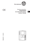
IMPORTANT: Chip installation should only be performed
by skilled personnel. Failure to install properly will
compromise operation of the AFC controller.
Chip Notch
1 Disconnect all connections from the AFC Controller.
2 Remove the eight capscrews from the controller box,
connector side. Remove the circuit board.
3 Use a flat blade screw driver to gently pry chip free.
4 Replace the chip with updated chip. Carefully align all
pins and firmly press the chip into sockets.
CAUTION: Align the notch on the chip with the notch on
the circuit board.
5 Insert the circuit board in the controller box u-shaped
AC1395.eps
guides. Install the eight capscrews.
6 Install new chip sticker onto the controller box for proper
3
identification.
7 Install the AFC Datalogger as described in Section
6
2.1-1.
5
2.1-3
Wiring Connections
Refer to the following diagram for proper connections.
12 Pin Cable Assembly
12 Pin Connector
Connector
Wires
Pin No.
Pin Name
Red ■
1
+ Vin
Black ■
2
- Vin
Pink
3
Tx1 - Out
Grey
4
Rx1 - In
Dark Brown
5
Com1
Orange
6
Tx2 - Out
White
7
Rx2 - In
Light Brown
8
Com2
Green
9
CanH
Violet
10
CanL
Yellow ❖
11
+ LED
Blue ❖
12
- LED
Input
Power Bus
Controller
Input (C1) ●
Scanner
Input (S1) ▲
CAN
Interface
(CN1) ♦
LED
Input
Pin No.
+
1
5
1
3
3
2
5
Black
White
9
6
Scanner Input
(socket side shown)
3
2
1
Controller Input (C1)
Anode
Cathode
■ Connect to a Nominal +12 to +24 VDC observing proper
polarity.
▲ Connect to a 9600 baud serial scanner.
● Connect to AFC Controller.
♦ Connect to CAN-based Cascade AFC Controller.
❖ Panel mounted 12V LED.
6075865-R4
AC1396.eps
2
3 2
6
5 4
7
8 9 10 11 12
1
12 Pin
Connector
(socket side
shown)
AC1826.eps
3
I
NSTALLATION
2.2
Software
2.2-1
Software Installation
1 Insert Cascade AFC Datalogger CD into the host
computer's CD-ROM. From the Start menu, go to 'My
Computer' and double left click on the CD-ROM icon.
AFC Datalogger CD content screen will appear.
2 Open the 'SerialNumber.txt' text file.
Highlight the serial
number. Copy the serial number by going to the 'Edit'
menu and selecting 'Copy'.
3 In the AFC Datalogger CD content screen, open
3
'AFCDataloggerSetup.exe' executable file. A setup
screen will appear. Left click the 'Next' button to
continue with the installation.
4 Read the license agreement and select the radio button
'I agree to the terms of this license agreement'. Left
click the 'Next' button to continue.
2
AC1397.eps
2
Highlight
Serial Number
3
AC1398.eps
Text Menu:
Edit
Select Copy
AC1399.eps
4
4
6075865-R4
I
NSTALLATION
Enter user name here
5 Enter the Name and Company into the appropriate text
boxes. Left click the 'Next' button.
6 Left click the Serial Number text box.
Paste the serial
number by holding the control (CRTL) key and pressing
the 'V' button (or right click in the text box and select
'paste'). Left click the 'Next' button.
7 The setup screen will provide information on were the
software will install. Left click the 'Next' to proceed with
the installation.
8 Another installer, Java 2 Platform, will appear.
• If the host computer does not have Java 2 installed,
a license agreement will appear. Accept the license
agreement and left click the 'Next' button.
• If the host computer has Java 2 installed, an
introduction screen will appear. Left click on the
'Next' button.
9 Java 2 will prompt for a type of installation. Choose
AC1400.eps
Enter company name here
'Typical' for a new installation or 'Modify' to update.
10 Left click the 'Next' button and wait for the software
11 The AFC Datalogger Setup screen will appear.
12 A desktop icon should have been created automatically.
13 Restart the host computer before opening the AFC
5
installs. When a screen appears asking to restart the
host computer, left click the 'No' button.
click the 'Finish' button.
Left
If the icon does not appear, create a desktop shortcut
with the 'AFC Datalogger.cmd' file found in the 'AFC
Datalogger' program folder.
Datalogger software.
6
AC1401.eps
Left click in text box to
paste serial number
11
Right click and select
paste
AC1403.eps
AC1402.eps
6075865-R4
7
5
I
2.2-2
NSTALLATION
Uninstalling Software
IMPORTANT: Uninstalling AFC Datalogger software will
result in deleting the database. Refer to section 4.6 to
create a backup.
1 From the window's 'Start' menu, select 'Programs' ➞
2
3
'AFC Datalogger' ➞ 'Uninstall AFC Datalogger'.
2 Left click the 'Yes' button to confirm uninstalling AFC
Datalogger software and all of its components.
AC1404.eps
3 Another prompt will appear asking to keep or remove
database files. Left click one of the following buttons:
• 'Yes' button to remove the database file.
• 'No' button to keep the database file.
4 Java 2 maintenance screen will appear, left click one of
the following buttons:
• 'Next' button to continue with uninstalling Jave 2
• "Cancel' button to keep Java 2 on the host
computer. Another prompt will appear asking to
confirm cancel. Left click the 'Yes' button. The
Java 2 maintenance screen will appear. Left click
the 'Finish' button. Go to Step 9.
5 Select the 'Remove' radio button and left click on the
'Next' button.
6 When the confirmation screen appears, left click on the
'Remove' button.
7 The software will uninstall.
A screen will appear
indicating software is uninstalled. Left click the 'Finish'
button.
8 The Java 2 software will ask to restart the computer. Left
click on the 'No' button.
9 AFC Datalogger Software will automatically uninstall.
When the message 'Uninstall complete' appears above
the progress bar, left click the 'Close' button.
AC1405.eps
10 Restart the computer.
5
Message will appear when
uninstall is complete
AC1406.eps
AC1407.eps
Progress Bar
6
9
6
6075865-R4
I
2.2-3
NSTALLATION
Network Settings
This setup is important for downloading data through an
ethernet connection.
1 From the window's 'Start' menu, select 'Settings' ➞
'Network Connection' ➞ 'Local Area Connection'.
2 Left click the 'Properties' button.
3 In the list box, select 'Internet Protocal (TCP/IP)' by left
clicking on the text once.
4 Left click the 'Properties' button.
5 Select the radio button 'Use the following IP Address'
and enter in the following information:
IP Address: 192.168.1.101
Subnet Mask: 225.225.225.0
NOTE: The Subnet Mask may appear automatically.
6 Left click the 'OK' button on each screen pertaining to
the network settings.
AC1408.eps
2
AC1410.eps
3
AC1409.eps
Left click once
6075865-R4
4
5
6
5
IP address
7
I
2.2-4
NSTALLATION
AFC Controller Setup-
Enable AFC Datalogger Function
The AFC controller needs to be configured to collect clamp
force data. Open the Hyperterminal file named 'AFC' (See
AFC Manual). The screen will show a blinking cursor. The
words 'arm movement' may appear on screen. Press
ENTER to bring up AFC main menu. Press ENTER again
and follow the on-screen prompts.
NOTE: Refer to the AFC manual for complete instructions
on configuring AFC settings.
CASCADE CORPORATION
ADAPTIVE FORCE CONTROL
NOTE: Type S for U.S units, M for Metric.
Cascade Corporation AFC System
Enter Desired Command at Prompt
2 SET THRESHOLD PRESSURES & CLAMPFORCE-TO-WEIGHT RATIOS
3 DIAGNOSTIC CALCULATIONS
4 TEST PRESSURE TRANSDUCERS
5 TEST SOLENOID VALVES
6 SET ACCUMULATOR PRESSURE
7 ADVANCED SETTINGS
8 ENABLE DATALOGGER
AC0228.eps
8.1
ENABLE DATALOGGER. ENTER Y OR N
PRESS ENTER
8.3
Type 'Y'
ENTER THE CLAMP FORCE CAPTURE
TIME
(250 to 6000 milliseconds, or type D
for default)
PRESS
ENTER
Cascade recommends '2500'
8.2
ENTER TRUCK ID #
(1-9999, or type D for default)
PRESS
ENTER
Type in a unique number that is different for
each truck. This ID number will show up in
the AFC Datalogger software.
8
8.4
ENTER THE HOIST PRESSURE
TRIGGER FACTOR
(1 - 50, or type D for default)
PRESS ENTER
Value is always 35 (default) unless
changed by Cascade.
6075865-R4
U
3.1
SING DATALOGGER HARDWARE
Collecting Clamp
Force Data
Turn Truck On
IMPORTANT: If a load is not lifted off the ground, the
clamp force and load weight field will read zero.
1 Turn truck on. Within ten seconds, the AFC Datalogger
LED should change from constantly lit to two rapid
flashes.
Clamp Load Until AFC
Clamp Ready Light
Turns On
2 Verify proper function by clamping a load or closing
arms until the Clamp Ready (AFC) light turns on. Open
arm(s). The LED should flash three times and then stay
off until the next clamp cycle.
3 Operate the clamp normally.
Each time the AFC
Controller Clamp Ready light goes from lit to off, the
AFC Datalogger LED will flash three times to indicate
data has been collected.
Each Clamp Cycle
Collects Data
NOTE: The weight reported by the AFC Datalogger
is an approximation only and does not represent the
actual legal load weight.
3.2
AFC Datalogger LED
The AFC Datalogger has a LED light that indicates status
to the operator. Use the following chart to determine if the
AFC Datalogger controller is functioning properly.
LED
INDICATES
RESULT
Constantly Lit
Occurs when the truck is initially
started. At any other point,
indicates the SD Card is not
mounted.
LED should go out in
approximately 10 seconds.
Not Lit
Normal operation, in use.
Not applicable.
2 Rapid Flashes
Ready and waiting to receive first
data.
Flashing stops once data is
received.
3 Rapid Flashes
Data is being received.
Flashing stops when no data is
transmitted.
4 Rapid Flashes
No Communication (Previous 5
minutes).
Sending new data will clear 4
rapid flashes. If 4 rapid flashes
continues after normal clamping
cycle, see Troubleshooting
Section (5.1-2).
6075865-R4
9
U
4.1
SING DATALOGGER SOFTWARE
Opening AFC
Datalogger Software
Enter Username: admin
1 From the window's 'Start' menu, select 'Program Files'
➞ 'AFC Datalogger' ➞ 'AFC Datalogger' or select the
'AFC Datalogger' shortcut on the desktop.
2 A command prompt will appear.
to appear.
Wait for a login screen
3 Enter username: admin.
4 Enter password: admin.
5 Left click on the 'Login' button.
6 Left click on a tab to perform a task. The 'Download' tab
AC1411.eps
5
Enter Password: admin
will automatically open upon login.
Selected screen will have a grayed tab
Unselected screen will have a dark blue tab
4.2
AC1412.eps
Navigating Through
The Software
The following chart shows the navigation of the
Datalogger application software.
Login Screen
Data Download
Tab
Reports
Tab
Setup
Tab
Maintenance
Tab
Troubleshooting
Tab
Choose method
to download
data
Choose type of
report
View Truck
See Software
Version
Identification
Contact
Cascade
Information
Download data
to database
Create report
Set Log
Time
(if required)
Export report
10
6075865-R4
U
4.3
SING DATALOGGER SOFTWARE
Downloading Data
Retrieving data from the AFC Datalogger can be done two
ways:
A Download data directly from the SD Card by using a
card reader,
OR
B Download data with an ethernet cable that connects
the AFC Datalogger to the host computer.
The SD Card has a LED light behind the access cover
to indicate its current status. Use the following chart to
determine if the SD Card is functioning properly.
LED
Indicates
Action
Constantly Lit
SD Card is mounted
To Unmount, press Mount/
Unmount button
Not Lit
SD Card is unmounted
OK to insert SD Card into slot
Flashing
SD Card error
Replace SD Card
IMPORTANT: Downloading data from the card reader is
quicker than from the ethernet cable.
4.3-1
Card Reader Method
1 Loosen thumbscrews and remove access cover from
the AFC Datalogger.
WARNING: Removing the SD Card before
the LED is 'off' can cause data to corrupt.
Press the Mount/Unmount button first and
wait for the LED light to turn off or turn truck
off.
2 Turn the truck off or push the Mount/Unmount button
2
86
75
60
tN
r
Pa
e
r:
60
75
86
3
c
vi
De
g
log
ta
Da
u
tN
ar
t P er,
m
be
4 Run the AFC Datalogger application software and login.
r:
reader into the host computer. The SD Card will appear
in 'My Computer' as a separate disk drive.
be
um
3 Insert the SD Card into a card reader. Plug the card
3
TM
next to the SD Card. Wait for the LED light to turn off.
Remove the SD Card from the AFC Datalogger.
Mount/Unmount
Button
Ki
See Section 4.1 for details.
1
6075865-R4
AC1413.eps
11
U
SING DATALOGGER SOFTWARE
10
AC1414.eps
5
9
5 In the 'Download' tab, left click on the 'Select' button.
6 If needed, use the file selection dialog to change the
7
location to access SD Card. The SD Card may be
named 'Removable Disk' with an assigned drive letter.
For example 'Removable Disk (E:)'.
7 Left click once on the 'Cascade' folder
8 Left click on the 'Open' button.
9 Left click the 'OK' button.
10 Once the display message, 'File Downloaded
Successfully for Trucks...,' the file(s) are deleted from
the SD Card.
NOTE: Clicking the 'Cancel' button will clear the
selection from the text box.
11 In the System Tray (typically located in the lower right
12 Left click on 'Safely Remove Hardware'.
13 Once a new screen appears, choose the drive (example
6
8
12
11
hand corner of the window's desktop screen), left click
on the Safely Remove Hardware icon.
USB Mass Storage Device) and left click the 'Stop'
button.
14 Left click on 'Generic Volume - (E:)' ('E' may be different)
15 Remove the SD Card from card reader and return it to
16 Turn the truck on.
AC1415.eps
and left click on the 'OK' button.
the AFC Datalogger card slot. Install the access cover.
If the truck is already on, press the
Mount/Unmount button once and wait (about 5 sec) for
LED to turn on.
13
14
12
AC1416.eps
6075865-R4
U
4.3-2
SING DATALOGGER SOFTWARE
Ethernet Method
The network connection must be setup on the host
computer to download data (see Section 2.2-4 to setup).
1 Connect the provided coupler and cross-over ethernet
cable to the AFC Datalogger and host computer.
A longer cross-over ethernet cable may be used, if
needed.
Appears when download is successful
2 Run AFC Datalogger software and login as described
in the section 4.1.
3 Left click on the 'Download' tab.
4 In the 'IP Address of the Unit' text box, verify that
the IP address is 192.168.1.103
5 Click 'Download Data from Network' button. Various
messages will appear to indicate the download
progress. When the download is complete, the
file(s) on the SD Card will be deleted.
AC1417.eps
4
3
1
IP Address for
the Datalogger
Controller
Host Computer
Ethernet Port
Connect cross-over ethernet
cable and coupler to AFC
Datalogger and host computer.
AFC Datalogger
Ethernet Cable
Cross-over
Ethernet
Cable
Coupler
g
log
ta
Da
um
tN
ar
t P er,
Ki
r:
be
6
58
7
60
3
ce
vi
De
rt
Pa
m
Nu
r:
be
63
8
75
60
TM
AC1444.eps
6075865-R4
13
U
4.4
SING DATALOGGER SOFTWARE
Creating Reports –
Error Message
Reports Tab
3
4 5
8
6
NOTE: The weight reported by the AFC Datalogger is an
approximation only and does not represent the actual legal
load weight.
4.4-1
Event Log
Event Logs are created to show a truck's clamp force
activity based on selected details.
NOTE: Dates entered must be in mm/dd/yyyy format or an
error message will appear.
1 Open the AFC Datalogger software as described in
section 4.1.
2 Select the 'Reports' tab.
3 Choose 'Event Log' in the drop down box.
4 Enter the starting date in mm/dd/yyyy format in the
indicated text box.
5 Enter the ending date in mm/dd/yyyy format in the
indicated text box.
6 Select the trucks to generate the report on. 'All' is
AC1676.eps
7
selected by default.
7 Select the details to show in the report. 'All' is selected
by default.
NOTE: To select more then one detail, hold the control
(CTRL) key and click on the details desired.
8 Left click the 'Run' button to create the report.
9 Refer to Section 4.4-4 to export reports to
Excel. Left click the 'Back' button to go
back to the main reports screen to create
another report.
AC1419.eps
9
14
See Section 4.4-4 to export a
report to Excel.
6075865-R4
U
4.4-2
SING DATALOGGER SOFTWARE
Equipment List
Equipment Lists are created to show trucks with their unit
IDs and additional unit information. To add additional
information about the unit, refer to Section 4.5-1.
2
1 Open the AFC Datalogger software as described in
section 4.1.
2 In the 'Download' tab, choose 'Equipment List' in the
drop down box.
3 Select the trucks to generate the report on. 'All' is
selected by default.
NOTE: To select more then one detail, hold the control
(CTRL) key and click on the details desired.
4 Click 'Run' to create the report.
5 Refer to Section 4.4-4 to export reports to Excel.
AC1420.eps
4
Left
click the 'Back' button to go back to the main reports
screen to create another report.
4.4-3
Download Log
3
2
Download Logs are created to list times and dates of when
data from a truck was downloaded.
1 Open the AFC Datalogger Software as described in
section 4.1.
2 In the 'Download' tab, choose "Download Log" in the
drop down box.
3 Click 'Run' to create the report.
4 Refer to Section 4.4-4 to export reports to Excel.
Left
click the 'Back' button to go back to the main reports
screen to create another report.
4.4-4
AC1421.eps
3
Export Reports to Excel
IMPORTANT: Reports that are exported will overwrite the
previous report. Always save a report in a new directory or
rename.
1 Create a report as described in the Sections 4.4-1, 4.4-2
or 4.4-3.
2 Click on 'Export to Excel' button.
• If an Excel file appears on the screen, go to Step 7 to
save the file to a new location or new name.
• If an Excel file does not appear, continue to Step 3.
4
3 Should the Excel file not appear, go to 'My Computer',
located on the desktop (located in the 'Start' menu).
4 Double left click on 'Local Drive (C:)' icon.
AC1422.eps
6075865-R4
15
U
SING DATALOGGER SOFTWARE
5 Double left click on the 'TEMP' folder icon.
6 Double left click on the 'report.xls' icon. This will open
the exported Excel file.
7 Go to the File Menu and select "Save As".
8 Select a location to save the file to and/or assign a
name. Save the file.
5
AC1423.eps
7
AC1424.eps
6
AC1425.eps
4.5
Setup Tab
The 'Vehicle Setup' tab shows assigned Truck IDs that
have been added to the software when data is downloaded
to the database. Truck IDs can be added manually to
the software; however, Cascade does not recommend
Truck IDs be added manually. To assign a Truck an ID for
distinguishing data, refer to the AFC Manual (Setup section
for Menu 8) or Section 2.2-4.
4.5-1
Click on drop down box arrow to view
Truck IDs currently stored in the software.
Add A Truck Description
1 Open the AFC Datalogger Software as described in
section 4.1.
2 In the 'Setup' tab, choose a Truck ID.
3 In the 'DCD Unit ID' text box, type the desired
description. For example, Truck 2 is located in
shipping. The user can assign a DCD Unit ID of
'Shipping" to Truck 2.
AC1426.eps
Saves entered
description.
Type description
in text box.
4 Click "OK" button to save the assigned DCD Unit ID.
16
6075865-R4
U
4.5-2
SING DATALOGGER SOFTWARE
Set Log Time
The following steps update the AFC Datalogger to the host
computer's current date and time.
IMPORTANT: The host computer must be connected to
the AFC Datalogger with an ethernet cable. See Section
2.2-3 for network setup. This allows the host computer and
AFC Datalogger to communicate.
1 Verify the correct day and time on the host computer
clock.
2 Connect the AFC Datalogger to the host computer using
the coupler and cross-over cable.
3 Open the AFC Datalogger Software as described in
section 4.1.
AC1445.eps
4
4 In the 'Setup' tab, click on the 'Set Log Time' button.
5 When the message 'Success' appears, disconnect the
cables.
6 Verify that the date and time are correct by clamping a
load and downloading data.
4.6
Maintenance Tab
4.6-1
Data Backup
1
Data that is downloaded is saved to a database file. It is
important to backup this database to another drive to
prevent lost information.
IMPORTANT: The 'Backup' button in the 'Maintenance' Tab
will not protect data. The database must be stored on a
separate drive as described below.
1 Enter today's date to backup file in mm/dd/yyyy format.
2 Click the 'Backup' button. The system will create a new
data set with a new name.
3 Open 'My Computer' from the desktop or from the 'Start'
menu.
4 Double left click on 'Local Drive (C:)' icon.
5 Double left click on 'Program Files' icon.
6 Double left click on 'AFC Datalogger' folder.
7 Right click on the 'Cascade_Database.mdb' icon
AC1427.eps
2
7
and choose 'Copy'.
IMPORTANT: Do not 'Cut' the database file.
Removing the file will cause new data to not be
stored and the software to error.
6075865-R4
AC1428.eps
17
U
SING DATALOGGER SOFTWARE
8 In another storage drive or an allocated folder on the
'C' drive, right click within the folder's window. When a
menu appears, select 'Paste'.
9 Rename the file with the backup date.
For example,
rename the file, 'Cascade_Database_04-07-2007.mdb'.
IMPORTANT: The file extension, ".mdb", must remain on
the end of the file name.
9
AC1429.eps
8
NOTE: In the event that a backup file is to be retrieved,
copy the backup file and paste in the 'AFC Datalogger'
folder (located in the 'Program Files' folder).
18
6075865-R4
T
ROUBLESHOOTING
Troubleshooting
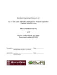
5.1-1 No Data in Report
5.1 Problem
Description
No Data in Report
Clamp load until
'Clamp Ready Light'
illuminates, then
OBSERVE the AFC
Datalogger LED while
opening
Check for proper
communication
connections
Problem
Corrected?
YES
NO
FLASH
2X
Go to
Troubleshooting
Section 5.1-2
FLASH 4X
LED
2X
Is the
SD Card
mounted?
Wait 15 seconds
and check again
YES
Power Cycle
the unit
Try new SD Card
YES
Call Cascade Corp.
Service Dept.
Reset AFC
Datalogger
Internal Clock
(Section 4.5-2)
Data Reported
OK
NO
YES
AFC Datalogger
Unit Malfunction.
Call Cascade Corp.
Service Dept.
6075865-R4
'Reports'
Date filter
formated
correctly?
YES
NO
YES
NO
AC1431.eps
X1
X2
NO
Problem
Corrected?
X1
X2
Data was
received from
clamp
Problem
Corrected?
NO
ON SOLID
FLASH
3X AND
SHUTS OFF
UNTIL NEXT
CYCLE
Check that
AFC setup has
Datalogger enabled
(Section 2.2-4)
1X
Mount SD Card
The System is
working correctly
LOG files
created on
SD Card?
NO
AFC Datalogger
Unit Malfunction.
Call Cascade Corp.
Service Dept.
YES
Application
Software
Problem
YES
LOG file
format
correct?
NO
AFC Datalogger
Unit Malfunction.
Call Cascade Corp.
Service Dept.
Uninstall and reinstall
AFC Datalogger
application Software
19
T
5.1-2
ROUBLESHOOTING
To Clear 4 Rapid Flashes
Problem
Description
No communication
Clamp load until
'Clamp Ready Light'
illuminates, then
OBSERVE the AFC
Datalogger LED while
opening
LED
FLASH 4X
FLASH
3X AND
SHUTS OFF
UNTIL NEXT
CYCLE
Data was
received from
clamp
Go to
Troubleshooting
Section 5.1-1
NO
Verify Data
Reported OK
1X
Power Cycle the unit
2X
Verify SD Card is
mounted correctly
3X
Reset clock, refer to
section 4.5-2
4X
Verify SD Card is not
damaged. Try new
card.
YES
5X
YES
Standard AFC −
Connect to
HyperTerminal and
verify data output
Data
Received
NO
6X
The System is
working correctly
AFC Datalogger
Unit Malfunction.
Call Cascade Corp.
Service Dept.
Problem in AFC
system
AC1493.eps
20
6075865-R4
P
ARTS
AFC Datalogger
Kit
r
Pa
t
be
m
Nu
r:
60
75
3
86
vic
De
e
r
Pa
tN
be
um
r:
60
75
86
3
TM
0
Q
1
2
TM
!
9
8
6
8
7
AC1836.eps
4
5
3
REF
1
2
3
4
5
6
7
8
9
10
11
QTY
1
1
1
1
1
1
1
1
2
1
1
PART NO.
PART NO.
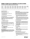
6075874
–
DESCRIPTION
–
6078997
AFC Datalogger Kit with
CAN Controller
6075866
6079614
Quick Start Kit ●
6075863
6078430
6078823
6075872
6078435
6079444
–
6079587
6081781
6081782
6081614
6075863
6078430
6078823
6075872
6078435
–
6079618 ▲
6079587
6081781
6081782
6081614
AFC Datalogger Kit
AFC Datalogger
CD and Case
SD Card Reader
Ethernet Cable, Cross-over
Ethernet Connector, F-F
Communication Cable
Communication Cable
LED light ✔
Thumbscrew ★
Access Cover ★
Firmware Upgrade Cable ■
● Includes items 2-5 and 6 or 7.
▲ CAN based.
✔ Included with Communication Cable.
★ Included in Access Door Assembly 6082512.
■ Not included in AFC Datalogger Kits.
Reference: 6078398, 6079611 (Sub Component Kits)
6075865-R4
21
P
ARTS
AFC Datalogger
with Scanner Input
Kit
r
Pa
be
um
tN
r:
60
86
75
3
vic
De
e
r
Pa
tN
be
um
6
r:
58
07
63
TM
0
Q
1
2
TM
!
9
8
7
6
8
AC1837.eps
5
4
3
REF
22
QTY
PART NO.
PART NO.
DESCRIPTION
6078996
–
AFC Datalogger Kit with
Scanner Input Option
–
6078998
AFC Datalogger Kit with
CAN Controller and
Scanner Input Option
6079646
6079641
Quick Start Kit ●
1
2
3
4
5
6
1
1
1
1
1
1
6075863
6078430
6078823
6075872
6078435
6079647
6075863
6078430
6078823
6075872
6078435
–
AFC Datalogger
CD and Case
SD Card Reader
Ethernet Cable, Cross-over
Ethernet Connector, F-F
Communication Cable
7
1
–
6079642 ▲
Communication Cable with
Scanner Input Option
8
9
10
11
1
2
1
1
6079587
6081781
6081782
6081614
6079587
6081781
6081782
6081614
LED light ✔
Thumbscrew ★
Access Cover ★
Firmware Upgrade Cable ■
● Includes items 2-5 and 6 or 7.
▲ CAN based.
✔ Included with Communication Cable.
★ Included in Access Door Assembly 6082512.
■ Not included in AFC Datalogger Kits.
Reference: 6079645, 6079640 (Sub Component Kits)
6075865-R4
P
ARTS
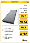
AFC Datalogger
Retrofit Kit Parts
Kit
r
Pa
tN
be
um
r:
60
75
86
3
vic
De
e
r
Pa
um
tN
be
6
r:
07
58
63
TM
0
Q
1
2
TM
9
6
7
4
5
3
8
REF
1
2
3
4
5
6
7
8
9
10
23
QTY
PART NO.
1
1
1
1
1
1
1
1
2
1
6078434
6075863
6078430
6078823
6075872
6078435
6079444
6079587
6073997
6081781
6081782
AC1838.eps
DESCRIPTION
AFC Datalogger Retrofit Kit
AFC Datalogger
CD and Case
SD Card Reader
Ethernet Cable, Cross-over
Ethernet Connector, F-F
Communication Cable
LED Light
E Prom – AFC Controller
Thumbscrews
Access Cover
6075865-R4
Do you have questions you need answered right now?
Call your nearest Cascade Service Department.
Visit us online at www.cascorp.com
AMERICAS
Cascade Corporation
U.S. Headquarters
2201 NE 201st
Fairview, OR 97024-9718
Tel: 800-CASCADE (227-2233)
Fax: 888-329-8207
Cascade do Brasil
Rua João Guerra, 134
Macuco, Santos - SP
Brasil 11015-130
Tel: 55-13-2105-8800
Fax: 55-13-2105-8899
Cascade Canada Inc.
5570 Timberlea Blvd.
Mississauga, Ontario
Canada L4W-4M6
Tel: 905-629-7777
Fax: 905-629-7785
EUROPE-AFRICA
Cascade Italia S.R.L.
European Headquarters
Via Dell’Artigianato 1
37050 Vago di Lavagno (VR)
Italy
Tel: 39-045-8989111
Fax: 39-045-8989160
Cascade (Africa) Pty. Ltd.
PO Box 625, Isando 1600
60A Steel Road
Sparton, Kempton Park
South Africa
Tel: 27-11-975-9240
Fax: 27-11-394-1147
ASIA-PACIFIC
Cascade Japan Ltd.
2-23, 2-Chome,
Kukuchi Nishimachi
Amagasaki, Hyogo
Japan, 661-0978
Tel: 81-6-6420-9771
Fax: 81-6-6420-9777
Cascade Korea
121B 9L Namdong Ind.
Complex, 691-8 Gojan-Dong
Namdong-Ku
Inchon, Korea
Tel: +82-32-821-2051
Fax: +82-32-821-2055
Cascade-Xiamen
No. 668 Yangguang Rd.
Xinyang Industrial Zone
Haicang, Xiamen City
Fujian Province
P.R. China 361026
Tel: 86-592-651-2500
Fax: 86-592-651-2571
Cascade Australia Pty. Ltd.
1445 Ipswich Road
Rocklea, QLD 4107
Australia
Tel: 1-800-227-223
Fax: +61 7 3373-7333
Cascade New Zealand
15 Ra Ora Drive
East Tamaki, Auckland
New Zealand
Tel: +64-9-273-9136
Fax: +64-9-273-9137
Sunstream Industries
Pte. Ltd.
18 Tuas South Street 5
Singapore 637796
Tel: +65-6795-7555
Fax: +65-6863-1368
Cascade India Material
Handling Private Limited
No 34, Global Trade Centre
1/1 Rambaugh Colony
Lal Bahadur Shastri Road,
Navi Peth, Pune 411 030
(Maharashtra) India
Phone: +91 020 2432 5490
Fax: +91 020 2433 0881
c
Cascade Corporation 2009
06-2009
Part Number 6075865-R4