1
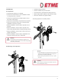
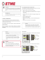
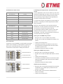
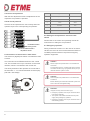
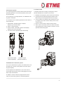
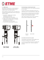
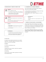
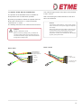
CAUTION ! 6.1 Connection to the control unit For operators with weights greater than 20 kg additional aids shall be used, such as hooks or ropes for securing and lifting. On the drives corresponding eyes are provided. The operator is factory wired to the control unit. If this is not the case, proceed as follows: Remove the cover from the operator. Run the cable gland of the cable into the correspon- INFORMATION ! The relevant instructions for the door must be observed when fitting the operator to the door. ding fitting. Connect the motor cable to the plug, the plug is po- larized. Connect the limit switch: AWG: connect plug 6. INITIAL OPERATION Power-operated doors shall be audited at least annually by a trained person, before first use and as required (with written proof). The operator of the door system, shall be trained after initial operation. Before installation, ensure that the direction of rotation of the gear motor is correct, and all protective devices are active. NOTICE ! To avoid damage to the drive, the following points must be observed: Mechanical limit switch: connect according to dia- gram Attach the cover back on the operator. NOTICE ! When mounting the motor cables to ensure that the individual wires are inserted deep enough and the screws are tightened so that a firm connection is made. This connection can be checked by pulling the cables. Connection Connection to cable set for mechanical limit switches: The types of cable and their diameters must be sel- U1 = BN ected according to current regulations. V1 = SW (BK) The nominal currents and the type of connection PE must correspond to those on the motor type plate. The drive details must agree with the connected W1 = BL (BU) loads. DANGER ! leer / empty Kabelsatz TAE Danger of fatal electric shock! Before commencing cabling works, you MUST disconnect the drive system from the mains supply. Ensure that the electricity supply remains disconnected throughout the cabling works. Connection to cable set for electronic limit switches: U1 = BN V1 = SW (BK) PE W1 = BL (BU) leer / empty Kabelsatz TAE 6