1
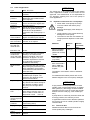
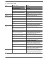
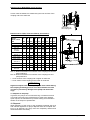
2.6 Limit of Application ATTENTION Type BFS, TFS, FFS Mediums Oils, cooling / cutting oils coolants Max. delivery pressure 150 bar (200 bar for BFS/FFS1, BFS/FFS2 and TFS/BFS/FFS3 upon request) Minimum discharge pressure Ensure that the discharge pressure is at least 2 bar higher than the inlet pressure Minimum inlet pressure 0.8 bar absolute, (Pumps with a flow rate of greater than 800 l/min have to be operated in conjunction with a feed pump > 1 bar). 1...45 mm /s (cSt) higher viscosities upon request Max. temperature of medium 60 °C over 60 °C on request Max. inlet pressure with mechanical seal < 7 bar Execution -G4 20 bar Concentration of coolant lubricants and water soluble coolants The fluid must have a minimum lubricity in accordance with industry standards. This corresponds to an approx. 4% concentration equivalent to mineral oil. A laboratory analysis is available at the factory. Minimum rpm Dry running Cycle times per hour 2.7 2 Kinetic viscosity of the medium Minimum flow rate The pumps are to be operated within their design limits. Applications outside of these limits are not approved. The manufacturer is not responsible for any damages resulting from use of the pumps in such applications. The minimum flow rate must be large enough to protect the pump from overheating. If necessary, consult with the manufacturer on exact flow rate. 25 Hz (1500rpm), lower rpm are available upon request. The minimum rpm depends on the pressure and medium. The pump MUST never be run dry without fluid. When testing for the direction of rotation, bump the pump for not longer than 1 second. Motors less 3 kW max. 200 from 3 kW to 4.0 kW max. 40 from 5.0 kW to 10 kW max. 20 larger than 10 kW max. 15 Maximum fluid 2 m/s velocity at pump suction Installation positions (Pump must not be installed with motor facing down) Piping / Fittings Pay attention to max. pressure ratings Ambient temperature 40 °C Set-up altitude 1000 m BE6100 Edition 03/2014 Important instructions for screw pumps Never allow screw pumps to run dry! Incorrect rotation will lead to pump damage! Sufficient fluid supply must always be ensured! Large particles in the coolant fluid may damage the screw pump! The limits for size and concentration of foreign particles depends on their hardness! Materials Particle size Particle concentration: Steel / Forgeable aluminium alloys (without Si content) / GG25 < 60 m < 177 mg/l Grey cast iron with hard additives (e.g. GGV) < 50 m < 63 mg/l Ceramic/ corundum / hard metal / glass / CBN Aluminium alloy with Si parts < 20 m < 19 mg/l The particle concentration refers to standardized test. For additional information please refer to the filtration diagram in the screw pump catalogue. ATTENTION If high pressure screw pumps are to be used outside of the recommended ranges, a suitable filter system (e.g. filter bags) must be installed upstream from the pump or pumps with special features must be used (e.g., with coated spindles). If pump failure is caused by excessive wear due to foreign particles, the warranty is void! In applications where hard or abrasive particles are present, the use of coated spindles is highly recommended. 2.8 Technical data Detailed technical data can be found in the screw spindle pump catalogue. Page 3 of 12