1
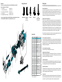
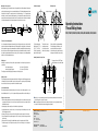
Machining of the component: Starting diameter d2 to be thread rolled must be the equivalent to the effective diameter. Deviations are possible, depending upon type of component material being used. The starting diameter arrived at now should never be increased. The components have to be chamfered under γ = 10° – 25° against the axis and must be concentric. An undercut at the thread run-out is not required. If an undercut is called for, the same should be chamfered according to sketch below. The diameter d1 must be below the root diameter of the thread. Also important is the accurate alignment of the head to the component. γ D γ d1 d2 Working Position Position for Assembly Looking at the gears Operating Instructions Thread Rolling Heads γ d1 d2 D F1C1, F12C1, F1223C1, F2C2, F23C2, F233400C2, F3C2, F34C2 Undercut Tolerance for the starting diameter: Once the accurate starting diameter, determined by a test rolling operation, has been found, then this should be considered as the maximum dimension, if the thread has been rolled just up to its crest and the effective diameter is approx. at the maximum dimension within the permissible thread tolerance. Among others the tolerance of the starting diameter is depending to what extent the thread has been rolled to. As a guide for standard threads with tolerance class 6 g the following may be used: starting diameter tolerance ≈ half effective diameter tolerance. The flats in the bores of the planet gears must be in the same position relative to the centre gear. Tooth is at right angle to the flat for types F 1, F 12, F 23, F 3, F 34, F 1223, F 233400. Gap is at right angle to the flat tor type F 2 Position of the flats for right-hand threads. For left-hand threads the flats are on the opposite side. With the assembly in the correct working position, shank and spring housing are mounted with closed coupling. Assembly Instruction for Spare Parts Rolling operation: The feed rate of approach should be equivalent to the pitch of thread to be rolled. After engagement over 3 – 4 thread pitches, the head itself takes over the feed movement. The support respectively the adaptor sleeve should be set-up tor easy movement in either direction at any rate. 6 3 Coolants and lubricants: Recommended coolants and lubricants are those, which are also used for cutting operations, i. e. solutions with diluted ratio of 1:10 up to 1:20 – perhaps with high pressure additives – and thin cutting oils. Possible errors to be made: 1. Effective starting diameter selected too large or head setting was too small, that means an overload is generated, which shows up in most cases as a bead on the thread crest over a length of the roll width at the thread end. 2. Chamfering (also at the undercut) is not in line with the rolling instructions. 3. Length adjustment was selected incorrect, or component length are deviating from each other (Rolls run against a shoulder). 4. Jamming of Rolls or signs of wear on the Eccentric Spindles caused by heavy dirt of the coolant. 5. Unclean thread start and possible damage to the Rolls caused by incorrect teed approach at the start of rolling. 6. Damage on the Rolls or rolling of two-start threads caused by incorrect assembly of the Rolls. 7. Premature opening of the Rolling Head caused by the wear of the Wedges for Coupling No. 1 or Coupling No. 2. Plug gauge 0.02 mm (.00787") larger than journal portion on eccentric spindle 4 Insert hone from this side ■■ If parts 3, 4 or 6 are re-ordered as spare parts, they should be assembled as shown on the sketch above; finishing work to be done if necessary. ■■ When assembling parts 5 and 8 in part 3, make sure that there is some play (clearance) between the parts. Part 5 must be able to rotate easily together with part 8. LMT FETTE Werkzeugtechnik GmbH & Co. KG Grabauer St. 24 21493 Schwarzenbek Germany Phone +49 4151 12 - 0 Fax +49 4151 12 - 3797 www.lmt-fette.com Rolling Head-Hotline +49 4151 12 - 391 E-Mail-Hotline [email protected] Printed in Germany, No. F1C1-F34C2 E (0111 3 DM/DH) Rolling Speed: According to component profile and spindle speeds available, the following rolling speeds are re- commended: for V-type threads approx. 20 – 60 m/min (65 – 200 ft/min) for Acme-type threads approx. 15 – 30 m/min (50 – 100 ft/min). The rolling speed is arrived at by figuring the same as tor the cutting speed. www.lmt-fette.com Changeable shanks IMPORTANT: In the case of re-ordering of Spare Parts, please state Rolling Head Type and Serial-No. Please note marking on the Front Plate! S = Special angle L = Design for Left Hand Threads SL = Special angle for Left Hand Threads X...= Special design Ke = Rolling Head for rolling of Serrations Rolling Heads F1C1, F12C1, F1223C1, F2C2, F23C2, F233400C2, F3C2, F34C2 (only for fixed application) Assembly of Thread RolIs: Remove front plate (4), apply a very thin coat of grease or a thin layer of MOLYKOTE to the eccentric spindles (5), as well as to the inclined surfaces on front- (4) and centre plate (3). If washer, part 25, is fitted in the rolling head, it should also be greased. Insert rolls (18) in the order 1-2-3 or A-B-C in clockwise direction. (For left hand heads in counter-clockwise direction.) Insert needle roller bearings (13) or carbide bushings. Fit front plate (4) to this assembly and tighten screws. (example F3S C2) (example F3L C2) (example F3SL C2) (example F3 C2 X 101) (example F3 Ke X 102) Straight shank Straight shank VDI shank HSK shank with flat (upon request) In case of re-ordering of Rolls, please state the Roll-Code-No., which is marked on the letter side of the Roll in addition to the dimension (e. g. for rolling head F3C2 e. g. 3/...)! Others e. g. tapered shanks (upon request) 15 24 10 7 If the length of the three slotted holes (2) is insufficient for the necessary adjustment and the zero mark “0” on the roller cage is at the ultimate minus setting, proceed as follows: Spare Parts 11 No. Pcs. 1 1 Clutch or shank 2 1 Spring housing 3 1 Centre plate 4 1 Front plate 5 3 Eccentric spindles 6 3 Spacing studs 7 1 Centre gear 8 3 Gear 92) 23 16 17 6 1 9 2 12 14 Description 1 Stud (Handle) 10 1 Coil spring 11 1 Circlip 12 1 Circlip 13 1 set 14 3 Counter-Sunk-Screws 15 3 Hexagon nut Needle roller bearings or carbide bush 8 3 5 22 18 13 4 21 20 16 1 Washer (ring type) 172) 1 Hexagon nut 18 3 Thread roll 20 1 Stop screw body 21 1 Stop screw 22 1 Stop screw lock nut 232) 1 Ball 24 1 Washer 251) 3 Washer 1) F12 C1, F23 C2, F233400 C2 and F34 C2 2) F1223 Adjustment of Head to thread diameter: The head is closed, i. e. the teeth of the coupling of parts 1 and 2 are in complete engagement. Parts 1 and 2 are spring loaded. First loosen three nuts (15) and insert between the rolls a screw plug gauge, or threaded sample, or if neither are available a plain plug with root diameter of the thread. The front part of the head (roller cage) is turned within the range of the three slotted holes (2) until the rolls (18) become fully engaged with the screw plug gauge, sample or plain plug. The three nuts (15) are then re-tightened. Should the effective diameter of the thread rolled not be correct, i. e. the effective diameter is too large, the three nuts (15) must be loosened and the front part of the head turned one half a calibration in the direction of the minus sign. A rolled thread should not be over rolled, or re-rolled a second time. C1 and F233400 C2 Head to be adjusted to a smaller diameter: Remove the three nuts (15) and ring type washer (16). The roller cage is then drawn off and turned round 120° approx, in the direction of the minus sign. It is then re-assembled. The secondary zero marking now appears on the plus side (+) of the scale. Ring type washer (16) and nuts (15) are put on again, the head finally adjusted to correct size as per previous paragraph and nuts are tightened. It is now possible to adjust the head to a smaller diameter. Head to be adjusted to a larger diameter: Same procedure as before, but turning direction is just reversed. Adjustment of Head to thread length: Adjustment to thread length is always done when the head is in an open position, i. e. the head is opened in axial direction by disengaging the dog coupling (1 and 2). This brings the front position of the head forward corresponding to the height of the dog coupling. Operation with Inside Stop: Stop screw (21) is adjusted to required thread length and locked by hexagon nut (22). If the component touches the stop screw (21), the dog coupling (1 and 2) is disengaged and the head opens automatically. The unclamped length of the component is not of decisive importance here. Operation with Outside Stop: The thread length, where chucking length is controlled, is set by a stop on the machine, which limits the forward travel of the sleeve, or the threading spindle or the turret slide. When the stop is reached, the dog coupling is disengaged and the head opens automatically. Closing of Head: When the head is closed, the rolls (18) are brought back into the rolling position. The front part oft he head is turned by using the handle (9) with ball (23), (if used on Automatics, closing is accomplished by using closing roller over a cam) until the coupling rests between the spring housing (2) and shank (1).