1
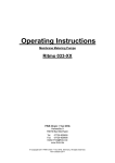
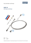
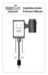
Operating Instructions Membrane Metering Pumps Ritmo 031-XX FINK Chem + Tec OHG Hofstraße 9 78073 Bad Dürrheim Tel. 07726-929655 Fax 07726-929656 [email protected] www.finkct.de © Copyright 2011 FINK Chem + Tec OHG, Germany. All rights reserved. 10 th October 2011 Contents Index of contents 1. 1.1 1.2 1.3 1.4 1.5 1.6 Safety instructions Identification of safety instructions in these instructions Qualification and training of personnel Safety instructions for the operator/ user Safety of the system in the event of a failure in the dosing pump Dosing chemicals Safety instructions for service, inspection and mounting 4 4 4 4 5 5 5 2. 2.1 2.2 2.3 2.4 2.5 2.6 General Warranty Applications Improper operating methods Nameplate Type key Device overview 6 6 6 6 7 8 9 3. 3.1 3.2 Technical data / dimensions Technical data Dimensions 9 9,10 11 4. 4.1 4.1.1 4.1.2 4.1.3 4.2 4.3 Assembly and installation Pump assembly Requirements Align and install mounting plate Engage pump in mounting plate Hydraulic connection Electrical connection 12 12 12 12 12 13 14 5. 5.1 5.2 5.3 Commissioning General notes Check before commissioning Start and dearate the pump 15 15 16 16 6. 6.1 6.2 6.2.1 6.2.2 6.2.3 6.3 6.3.1 6.3.2 6.3.3 Operation Operating elements Operation modes Manual Pulse Change operation modes Inputs External stop Empty signal Change contact type 16 16 17 17 17 18 18 18 18 18 7. 7.1 7.2 7.2.1 7.2.2 7.2.3 7.3 Service Service intervals Perform service Dosing head overview Dismantling the diaphragm and valves Reassembling the diaphragm and valves Repairs 18 19 19 19 19 20 20 8. 8.1 8.1 Faults Indication of faults List of faults 20 20 21 2 9. Disposal 21 10. Safety declaration 22 11. EG- Declaration of Conformity 23 3 1. Safety instructions These installation and operating instructions contain general instructions that must be observed during installation, operation and maintenance of the pump. It must therefore be read by the installation engineer and the relevant qualified operator prior to installation and start-up, and must be available at the installation location at all times. Apart from these general safety instructions there are further special instructions in other sections to which attention must be given. The instructions mounted directly on the metering pump must be heeded and always kept in a visible condition. Besides the general safety instructions the operator must consider the existing national regulations for accident prevention as well as the internal working, company, and safety regulations. 1.1. Identification of safety instructions in these instructions The safety instructions are identified by the following symbols: Warning If these safety instructions are not observed, it may result in personal injury! Caution If these safety instructions are not observed, it may result in malfunction or damage to the equipment! Note Notes or instructions that make the job easier and ensure safe operation. 1.2 Qualification and training of personnel The personnel responsible for the installation, operation and service must be appropriately qualified for these tasks. Areas of responsibility, levels of authority and the supervision of the personnel must be precisely defined by the operator. If necessary, the personnel must be trained appropriately. Risks of not observing the safety instructions Non-observance of the safety instructions may have dangerous consequences for the personnel, the environment and the pump and may result in the loss of any claims for damages. It may lead to the following hazards: - Personal injury from exposure to electrical, mechanical and chemical influences. - Damage to the environment and personal injury from leakage of harmful substances. 1.3 Safety instructions for the operator/ user The safety instructions described in these instructions, existing national regulations on health protection, environmental protection and for accident prevention and any internal working, operating and safety regulations of the operator must be observed. Information attached to the pump must be observed. Leakages of dangerous substances must be disposed of in a way that is not harmful to the personnel or the environment. Damage caused by electrical energy must be prevented, see the regulations of the local electricity supply company and the regulations VDE. Caution Before starting work on the pump, the pump must be disconnected from the mains. The system must be pressureless! Only original accessories and original spare parts should be used. Using other parts can result in exemption from liability for any resulting consequences. An existing guards for moving parts must not be removed while the system is in operation. 4 1.4 Safety of the system in the event of a failure in the dosing pump The dosing pump was designed according to the latest technologies and is carefully manufactured and tested. If it fails regardless of this, the safety of the overall system must be ensured. Use the relevant monitoring and control functions for this. Caution Make sure that any chemicals that are released from the pump or any damaged lines do not cause damage to system parts and buildings. The installation of leak monitoring solutions and drip trays is recommended. 1.5 Dosing chemicals Warning Before switching the supply voltage back on, the dosing lines must be connected in such a way that any chemicals in the dosing head cannot spray about and put people at risk. The dosing medium is pressurized and can be harmful to health and the environment. Warning When working with chemicals, the accident prevention regulations applicable at the installation site should be applied (e.g. wearing protective clothing). Observe the chemical manufacturer´s safety data sheets and safety instructions when handling chemicals! Caution Warning If the diaphragm leaks or is broken, dosing liquid will escape from the discharge opening on the dosing head (see fig. 2). Take suitable precautions to prevent harm to health and damage to property from escaping dosing liquid! Check daily whether liquid is escaping from the discharge opening! Changing the diaphragm, see section 7. Service. A deaeration hose, which is routed into a container, e.g. a drip tray, must be connected to the deaeration valve. Caution The dosing medium must be in liquid aggregate state! Observe the freezing and boiling points of the dosing medium! Caution The resistance of the parts that come into contact with the dosing medium, such as the dosing head, valve ball, gaskets and lines, depends on the medium, media temperature and operating pressure. Ensure that parts in contact with the dosing medium are resistant to the dosing medium under operation conditions. Should you have any questions regarding the material resistance and suitability of the pump for specific dosing media, please contact with Fink Chem + Tec OHG 1.6 Safety instructions for service, inspection and mounting The organization is responsible for execution of all service, inspection and mounting work is only done through authorized qualified persons who are instructed with an adequate study of the mounting and operating instructions. Fundamentally, all work on the metering pump is executed only when the pump is not running. The stopping procedure of the pump must be executed as described in the operating instructions. Directly after termination of a process all safety and protection fittings must be placed back into place i.e. set in to function. Before renewed operation all instructions in the section ‘Putting into operation’ must be executed. 5 2. General The dosing pump R031 is a self-priming diaphragm pump. It consists of a housing with stepper motor and electronics and a dosing head with diaphragm and valves. Excellent dosing features of the pump: - Optimal intake even with degassing media, as the pump always works at full suction stroke volume. - Continuous dosing, as the medium is sucked up with a short suction stroke, regardless of the current dosing flow, and dosed with the longest possible dosing stroke. 2.1 Warranty A guarantee claim in accordance with our general terms of sale and delivery is only valid if the following requirements are fulfilled: - The pump is used in accordance with the information within this manual. - The pump is not dismantled or incorrectly handled. - The maintenance is carried out by authorised and qualified personnel. - Original spare parts are used for repairs during maintenance. 2.2 Applications The pump is suitable for liquid, non-abrasive, non-flammable and non-combustible media strictly in accordance with the instructions in these installation and operating instructions. The stated limiting values as shown in the technical data must not be exceeded in any case. Areas of Applikation - Drinking water treatment Wastewater treatment Swimming pool water treatment Boiler water treatment CIP (Clean-In-Place) Cooling water treatment Process water treatment Wash plants Chemical industry Ultrafiltration processes and reverse osmosis Irrigation Paper and pulp industry Food and beverage industries 2.3 Improper operating methods The operational safety of the pump is only guaranteed if it is used in accordance with section 2.2 Applications. Caution Frequent disengagement from the mains voltage, e.g. via a relay, can result in damage to the pump electronics and to the breakdown of the pump. The dosing accuracy is also reduced as a result of internal start procedures.´ Do not control the pump via the mains voltage for dosing purposes! Only use the ’External stop’ function to start and stop the pump! Warning Other applications or the operation of pumps in ambient and operation conditions, which are not approved, are considered improper and are not permitted. The Fink Chem + Tec OHG cannot be held liable for any damage resulting from incorrect use. 6 Warning The pump is NOT approved for operation in potentially explosive areas! Warning A sunscreen is required for outdoor installation! 2.4 Nameplate Fig. 1 Nameplate 7 2.5 Type key The type key is used to identify the precise pump and is not used for configuration purposes. Code G Example R031 6- 10 P- PP/ V/ C- X- 3 1 U2U2 F G Design Grundfos___________________________________________________________________________________________ * including: 2 pump connections, foot valve, injection unit, 6 m PE discharge hose, 2 m PVC suction hose, 2 m PVC deaeration hose (4/6 mm). 8 2.6 Device overview Valve, discharge side Operating elements (Section. 6.1) Capacity adjustment knop Keys and status LED* Mechanical lock Deaeration valve (Section 5.3) Dosing head Connection, deaeration hose Drain opening in case of diaphragm breakage Signal inputs* (Section 4.3) Mains connection Mounting plate * Only control variant R031-P Valve, suction side Fig. 2 Overview 3. Technical data / dimensions 3.1 Technical data Pump type R031Data Turndown ration (setting range) Max. dosing flow Min. Dosing flow Max. operating pressure 1) Mechanical data Max. stroke frequency Stroke volume Accuracy of repeatability 2) Max. suction lift during operation Max. suction lift when priming with wet 2) valves Min. pressure difference between suction and discharge side Max. pressure, suction side 3) Max. viscosity with spring-loaded valves 3) Max. viscosity without spring-loaded valves Min. diameter of hose/pipe 2)4) on suction/discharge side Min. diameter of hose/pipe on suction side for 4) highly viscous media (HV) Min. diameter of hose/pipe on discharge side 4) for highly viscous media (HV) Max. media temperature Min. media temperature [1:X] [l/h] [gph] [l/h] [gph] [bar] [psi] [strokes/min] [ml] [%] [ml] [m] 6-10 1000 6,0 1,5 0,006 0,0015 10 150 140 0,81 2 [bar] 15-4 1000 15,0 4,0 0,015 0,0040 4 60 180 1,58 +/- 5 6 3 1 [bar] [mPas](=cP) [mPas](=cP) 600 2 [mm] 4 500 50 6 [mm] 9 [mm] 9 [°C] [°C] 45 -10 9 Data 6-10 Mechanical data Electrical data Signal input 1) Weight /size Sound pressure level Approvals Max. ambient temperature Min. ambient temperature Max. storage temperature Min. storage temperature Voltage Length of mains cable Max. current consumption (100 V) Max. current consumption (230 V) Max. power consumption P1 Enclosure class Electrical saftey class Max. load for level input Max. load for pulse input Max. load for external stop Min. pulse length Max. pulse frequency Max. resistance in level circuit Max. resistance in pulse circuit Weight (PVC, PP, PVDF) Weight (stainless steel) Diaphragm diameter Max. sound pressure level [°C] [°C] [°C] [°C] [V] [m] [A] [A] [W] [ms] [Hz] [Ω] [Ω] [kg] [kg] [mm] [dB(A)] 15-4 45 0 70 -20 100-240 V, 50-60 Hz 1,5 0,12 0,05 12 IP 65, Nema 4X II 12 V, 5 mA 12 V, 5 mA 12 V, 5 mA 5 100 1000 1000 2,4 3,2 44 50 60 CE, CSA-US, NSF61, GHOST, C-Tick 1) Applies to R031-P control variant 2) Data is based on measurements with water 3) Maximum suction lift: 1 m, dosing flow reduced (approx. 30%) 4) Length of suction line: 1.5 m / length of discharge line: 10 m (at max. viscosity) 10 3.2 Dimensions The indicated dimensions are the same for all control variants of the R031 range. The following drawing shows the R031-P control variant. Fig.3 Dimensional drawing Pump type A1 (mm) B (mm) C (mm) D (mm) R031-6-10 251 196 46,5 24 R031-15-4 251 200,5 39,5 24 11 4. Assembly and installation 4.1 Pump assembly The pump is delivered with a mounting plate. The mounting plate can be mounted vertically, e.g. on a wall, or horizontally, e.g. on a tank. It takes just a few quick steps to firmly secure the pump to the mounting plate by means of a slot mechanism. The pump can easily be released from the mounting plate for maintenance. 4.1.1 Requirements - The mounting surface must be stable and must not vibrate. Dosing must flow upwards vertically. 4.1.2 Align and install mounting plate - Vertical installation: Mounting plate slot mechanism must be above. Horizontal installation: Mounting plate slot mechanism must be opposite the dosing head. The mounting plate can be used as a drill template, please see fig. 3 for drill hole distances. Fig. 4 Locate mounting plate Warning Make sure that you do not damage any cables and lines during installation! 1. Indicate drill holes. 2. Drill holes. 3. Secure mounting plate using four screws, diameter 5 mm, to the wall, on the bracket or the tank. 4.1.3 Engage pump in mounting plate 1. Attach the pump to the mounting plate support clamps and slide under slight pressure until it engages. Fig. 5 Engaging the pump 12 4.2 Hydraulic connection Warning Risk of chemical burns! Wear protective clothing (gloves and goggles) when working on the dosing head, connections or lines! Caution The dosing head may contain water from the factory check! When dosing media which should not come into contact with water, another medium must b dosed beforehand! Caution Faultless function can only be guaranteed in conjunction with lines supplied by Fink Chem + Tec OHG Caution The lines used must comply with the pressure limits as per section 3.1 Technical data! Important information on installation - Observe suction lift and hose diameter, see section 3.1 Technical data. - Shorten hoses at right angles. - Ensure that there are no loops or kinks in the hoses. - Keep suction line as short as possible. - Route suction line up towards the suction valve. - Installing a filter in the suction line protects the entire installation against dirt and reduces the risk of leakage. Hose connection procedure 1. Push union nut and tensioning ring across hose. 2. Push cone part fully into the hose, see fig. 6. 3. Attach cone part with hose to the corresponding pump valve. 4. Tighten union nuts manually – do not use tools! 5. Tighten up union nuts after 2-5 operating hours, if using PTFE gaskets! 6. Attach deaeration hose to the corresponding connection (see fig. 2) and run into a container or a collecting tray. Fig. 6 Hydraulic connection Note Pressure differential between suction and discharge side must be at least 1 bar/14.5 psi! Caution Tighten up the dosing head screws once before commissioning and after 2-5 operating hours at 3 Nm. 13 Installation example The pump offers various installation options. In the picture below, the pump is installed in conjunction with a suction line, level switch and multifunction valve on a Fink Chem + Tec OHG tank. Fig. 7 Installation example 4.3 Electrical connection Mains connection Warning The enclosure class (IP65/Nema 4X) is only guaranteed if lugs or protective caps or correctly installed! Warning The pump can start automatically when the mains voltage is switched on! Do not manipulate mains plug or cable! The pump is supplied with assembled mains cable and plug 1. Set capacity adjustment knob to 0% (see 6.1 Operating elements). 2. Connect the mains plug with the mains socket. 14 Signal connections Applies to R031-P control variant. Fig. 8 Wiring diagram of the electrical connections (R031-P) 5. Commissioning 5.1 General notes Warning Suction and discharge hoses must be connected correctly! The deaeration hose must be connected correctly and inserted into a suitable tank! Caution Tighten up the dosing head screws once before commissioning and after 2-+5 operating hours at 3 Nm. 15 5.2 Check before commissioning - Check that the rated voltage indicated on the nameplate complies with the local conditions. Check that all connections are assembled correctly. Tighten connections, if necessary. Check that the dosing head screws are tightened with the indicated torque (3 Nm). Tighten dosing head screws, if necessary. Check that all electrical cables and plugs are connected correctly. 5.3 Start and dearate the pump Connect mains supply (see 4.3 Electrical connection). Open the deaeration screw by approximately half a turn. R031-P Control variant: Press the deaeration key (1200%) and hold it down, until liquid flows out of the deaeration hose continuously and without any bubbles - R031-B Control variant: Turn the capacity adjustment knob to 100% and wait, until liquid flows out of the deaeration hose continuously and without any bubbles. Then set the capacity adjustment knob back to 0% - Close the deaeration screw. The pump is deaerated. - 6. Operation 6.1 Operating elements Fig. 9 Operating elements Capacity adjustment knob The capacity adjustment knob is used to set the capacity in percent of the maximum dosing flow of the pump. Due to the logarithmical increase of the percent values, even small dosing capacities can be set accurately. Mechanical lock The mechanical lock protects the set dosing capacity against unauthorised manipulation. For locking, tighten the screw until the adjustment knob cannot be turned anymore. Keys and LEDs * Applies to R031-P control variant. When pressing and holding down the deaeration key, the pump doses at 100% for a certain time. The deaeration key can be used e.g. for deaeration. The operation mode switch is used to change between the ’Manual’ and ’Pulse’ modes (see section 6.2.3). According to the selected operation mode, the respective status LED is active (‘pulse’ = LED above switch; ‘manual’=LED below switch). . 16 The status LEDs indicate the following operating statuses and faults: 6.2 Operation modes Following operation modes are available: - Manual, see section 6.2.1 Pulse*, see section 6.2.2 *Applies to R031-P control variant. 6.2.1 Manual In this operation mode, the pump doses constantly the dosing quantity set by adjustment knob. The setting range depends on the pump type: Type R031-6-10 R031-15-4 Setting range (l/h) 6 ml/h – 6 l/h 15 ml/h – 15 l/h 6.2.2 Pulse Applies to R031-P control variant. In this operation mode, the pump doses the set dosing volume for each incoming (potential-free) pulse, e.g. from a water meter. There is no direct connection between incoming pulses and dosing strokes. The pump automatically calculates the optimum stroke frequency for dosing the set volume per pulse. The calculation is based on: - the frequency of external pulses - the set stroke volume in percent. The dosing quantity per pulse is set to a value between 0.1% and 100% of the stroke volume using the adjustment knob. The setting range depends on the pump type: Type R031-6-10 R031-15-4 Setting range 0,8 µl – 0,81 ml 1,6 µl – 1,58 ml The frequency of incoming pulses is multiplied by the set dosing volume. If the pump receives more pulses than it can process at the maximum dosing flow, it runs at the maximum stroke frequency in continuous operation. Excess pulses will be ignored if the memory function is not enabled. 17 6.2.3 Change operation modes Applies to R031-P control variant. 1. Set adjustment knob to 0% 2. Connect mains supply (see section 4.3 Electrical connection). 3. Hold down the operation mode switch for at least 5 seconds. The new operation mode is saved. 6.3 Inputs Applies to R031-P control variant. 6.3.1 External stop The pump can be stopped via an external pulse, e.g. from a control room. When activating the external stop pulse, the pump switches from the operational state ‘Running’ into the operational state ‘Standby’. According to the selected operation mode, the respective LED flashes yellow. Caution Frequent disengagement from the mains voltage, e.g. via a relay, can result in damage to the pump electronics and to the breakdown of the pump. The dosing accuracy is also reduced as a result of internal start procedures. Do not control the pump via the mains voltage for dosing purposes! Only use the ‘External stop’ function to start and stop the pump! 6.3.2 Empty signal In order to monitor the filling level in the tank, a one-level sensor (empty signal) can be connected to the pump. The pump reacts to the signal as follows: - the active status LED flashes red - the pump stops. Caution When the tank is filled up again, the pump restarts automatically! 6.3.3 Change contact type The signal inputs (empty signal and external stop) are configured at the factory as normally open (NO) contacts. They can be re-configured as normally closed (NC) contacts. The re-configuration is always made for both inputs. 1. Set adjustment knob to 0%. 2. Connect mains supply (see section 4.3 Electrical connection). 3. Press deaeration key and operation mode key simultaneously and hold them down for at least 2 seconds. The new contact type is saved. 7. Service In order to ensure a long service life and dosing accuracy, wearing parts such as diaphragms and valves must be regularly checked for signs of wear. Where necessary, replace worn parts with original spare parts made from suitable materials. Should you have any questions, please contact with us. Warning If the diaphragm leaks or is broken, dosing liquid will escape from the discharge opening on the dosing head (see fig. 2). Take suitable precautions to prevent harm to health and damage to property caused by escaping dosing liquid! Check daily whether liquid is escaping from the discharge opening! 18 7.1 Service intervals Interval Task Check, if liquid leaks from dosing head, drain opening or valves (see fig. 2). If necessary, tighten dosing head screws (3Nm), valves and cap nuts, or perform service (see 7.2 Perform service). Every day Every 2 years or 8000 operating hours Replace diaphragm and valves (see 7.2 Perform service) 7.2 Perform service Only spare parts and accessories from Fink Chem + Tec OHG should be used for maintenance. The usage of non-original spare parts and accessories renders any liability for resulting damages null and void. I Warning When dosing dangerous media, observe corresponding precautions in the safety data sheets! Risk of chemical burns! Wear protective clothing (gloves and goggles) when working on the dosing head, connections or lines! Do not allow any chemicals to leak from the pump. Collect and dispose of all chemicals correctly! Caution Before any work to the pump, the pump must be disconnected from the mains. The system must be pressureless! 7.2.1 Dosing head overview 1 2 3 4 5 6 7 8 9 10 Safety diaphragm Flange O-ring Diaphragm Valve on discharge side Valve on suction side Dosing head Screws with discs Cover Deaeration valve Fig. 10 Dosing head, exploded view 7.2.2 Dismantling the diaphragm and valves 1. 2. 3. 4. 5. 6. 7. 8. 9. 10. 11. Make system pressureless. Empty the dosing head before maintenance and flush it if necessary. Set adjustment knob to 0%. Switch off mains supply. Take suitable steps to ensure that the returning liquid is safely collected. Dismantle suction, pressure and deaeration hoses. Dismantle valves on suction and discharge side (5, 6). Remove the cover (9). Loosen screws (8) on the dosing head (7) and remove the screws and discs. Remove the dosing head (7). Unscrew diaphragm (4) counter-clockwise and remove with flange (2) 19 7.2.3 Reassembling the diaphragm and valves 1. Attach flange (2) correctly and screw on new diaphragm (4) clockwise. - Make sure that the O-ring (3) is seated correctly! 2. Connect / switch on mains supply. 3. Turn the adjustment knob slowly to bring the diaphragm into its serviced position ‘inside’ (end of suction phase, diaphragm retracted). Set adjustment knob back to 0% 4. Switch off mains supply again. 5. Attach the dosing head (7). 6. Install screws with discs (8) and cross-tighten. - Torque: 3 Nm. 7. Attach the cover (9) 8. Install new valves (5, 6). - Do not interchange valves and pay attention to direction of arrow. 9. Connect suction, pressure and deaeration hoses (see section 4.2 Hydraulic connection). 10. Deaerate dosing pump (see section 5.3 Start and deaerate the pump). 11. Please ovserve the notes on commissioning in section 5. Commissioning! 7.3 Repairs Warning The pump housing must only be opened by personnel authorised by Fink Chem + Tec OHG! Repairs must only be carried out by authorised and qualified personnel! Switch off the pump and disconnect it form the voltage supply before carrying out maintenance work and repairs! After consulting Fink Chem + Tec OHG, please send the pump, together with the safety declaration completed by a specialist, to Fink Chem + Tec OHG. The safety declaration can be found at the end of these instructions. It must be copied, completed and attached to the pump. Caution If the pump has been used to dose toxic liquids or liquids hazardous to health, the pump must be cleaned prior to dispatch! If the above requirements are not met, the Fink Chem + Tec OHG may refuse to accept delivery of the pump. The shipping costs will be charged to the sender. 8. Faults 8.1 Indication of faults Depending on the selected operation mode, the pump indicates the following faults with its LEDs: LED colour Fault red empty signal red (flashing) motor blocked Remedy fill tank check contact type (see section 6.3.3). reduce backpressure. have gear repaired, if necessary. For further faults, please see 8.2 List of faults. 20 8.2 List of faults Fault 1. Dosing flow too high 2. No dosing flow or dosing flow too low Possible cause a) Inlet pressure greater than backpressure Possible remedy Install additional spring loaded valve (approx. 3 bar) on the discharge side. Increase pressure differential a) Air in dosing head Deaerate the pump. b) Faulty diaphragm Change the diaphragm (see section 7.2 Perform service). Check and repair lines. Check and clean valves. Check that the arrow on the valve housing is pointing in the direction of flow. Check whether all O-rings are installed correctly. Clean suction line/install filter. Reduce suction lift. Install priming aid. Use hose with larger diameter. Install spring-loaded valve on the discharge side. Close the deaeration valve. Tighten up valves, replace valves if necessary (see section 7.2 Perform service) Keep backpressure constant. ´Change the diaphragm (see 7.2 Perform service).) Tighten up screws (see section 4.2 Hydraulic connection). Tighten up valves/union nuts (see section 4.2 Hydraulic connection). Reduce suction lift; if necessary, provide positive inlet pressure. Open the deaeration valve. c) Leakage/fracture in lines d) Valves leaking or blocked e) Valves installed incorrectly f) Blocked suction line g) Suction lift too high h) Viscosity too high 3. Irregular dosing 4. Liquid escaping from the discharge opening on the flange 5. Liquid escaping 6. Pump not sucking in i) Deaeration valve open a) Valves leaking or blocked b) Backpressure fluctuations a) Faulty diaphragm a) Dosing head screws not screwed in as far as they will go b) Valves not screwed in as far as they will go a) Suction lift too high b) Backpressure too high c) Soiled valves Flush system, replace valves if necessary (see section 7.2 Perform service). 9. Disposal This product and all its associated parts must be disposed of in an environmentally friendly manner. Use appropriate waste collection services. If there is no such facility or the facility refuses to accept these materials used in the product, the product can be sent to the Fink Chem + Tec OHG. 21 Appendix Safety declaration Please copy, fill in and sign this sheet and attach it to the pump returned for service. Product type (nameplate ______________________________________ Model- number (nameplate ______________________________________ Dosing medium _____________________________________ Fault description Please make a circle around the damaged parts. In the case of an electrical or functional fault, please mark the cabinet. Please describe the error / cause of the error in brief. We hereby declare that the pump has been cleaned and is completely free from chemical, biological and radioactive substances. __________________________________ Date, signature and Company stamp 2011 Fink Chem + Tec OHG The texts, images and examples in this manual are carefully compiled. Fink Chem + Tec OHG is not liable for possible remaining incorrect details and following consequences or breach of other third party rights neither legal responsibility nor other liability. We are thankful for any notifications or improvement suggestions. The material, Soft and Hardware terms and names mentioned in this manual are usually registered trademarks and underlie the legal regulations. The manual protected by copyright. All rights reserved. No part of this manual may be reproduced by photo copy, microfilm or other means or transferred to machines, especially data processing equipment, in the appropriate language. Presentation by submission in lectures, radio and television is allowed only with our written consent. 22 EG - Declaration of Conformity Machinery Directive 2006/42/EG, II 1, A Membrane Metering Pumps R 031-xxx Manufacturer Fink Chem+Tec OHG Hofstraße 9 D-78073 Bad Dürrheim We declare that this delivered R 031/DDE Metering Pump and in all versions are in conformity with the following standards or standardized documents according to the provisions of the directives of the EC state members. – Machinery Directive (2006/42/EG). Standards used: EN 809: 1998 EN ISO 12100-1+A1: 2009 EN ISO 12100-2+A1: 2009 – EMC Directive (2004/108/EG). Standards used: EN 61000-6-2: 2005, EN 61000-6-4: 2007 – Low Voltage Directive (2006/95/EG). Standard used: EN 60204-1+A1: 2009 – Electrical equipment applicated within specified voltage ranges Norm EN 61 010 -1 und EN 61 010-2-010/A1 Person authorised to compile technical file and empowered to sign the EC declaration of conformity. Manufacturer/Supplier Grundfos/Fink Chem+Tec OHG D. Fink Date 06.09.2011 23