1
INOVA
Solids Hardware
Installation
UNITY
UNITY
INOVA NMR Spectrometer Systems
Pub. No. 01-999044-00, Rev. A0398
UNITYINOVA
Solids Hardware Installation
NMR Spectrometer Systems
Pub. No. 01-999044-00, Rev. A0398
UNITYINOVA
Revision history:
A0896 – Initial release as Pub. No. 87-195482-00
A0297 – Updated for VNMR 5.3
A0398 – Initial release as Pub. No. 01-999044-00
Applicability of manual:
Installatioon of the solids modules on Varian UNITYINOVA NMR spectrometers:
Rotor Synchronization (Part No. 01-903728-00)
Wideband NMR Module (Part No. 01-903007-00)
Wideline Solids Module (00-990488-0x)
CP/MAS Solids Module (Part Nos. 00-990402-04, 00-990403-04, 00-990404-04)
CRAMPS/Multipulse Solids Module (Part No. 00-990487-0x)
Technical contributors: Frits Vosman, Dave Rice, Phil Hornung,
Laima Baltusis, Ron Haner
Technical writer: Dan Steele
Technical editor: James Welch
Copyright 1999 by Varian, Inc.
3120 Hansen Way, Palo Alto, California 94304
http://www.varianinc.com
All rights reserved. Printed in the United States.
The information in this document has been carefully checked and is believed to be
entirely reliable. However, no responsibility is assumed for inaccuracies. Statements in
this document are not intended to create any warranty, expressed or implied.
Specifications and performance characteristics of the software described in this manual
may be changed at any time without notice. Varian reserves the right to make changes in
any products herein to improve reliability, function, or design. Varian does not assume
any liability arising out of the application or use of any product or circuit described
herein; neither does it convey any license under its patent rights nor the rights of others.
Inclusion in this document does not imply that any particular feature is standard on the
instrument.
UNITYINOVA, MERCURY, Gemini, GEMINI 2000, UNITYplus, UNITY, VXR, XL, VNMR,
VnmrS, VnmrX, VnmrI, VnmrV, VnmrSGI, MAGICAL II, AutoLock, AutoShim,
AutoPhase, limNET, ASM, and SMS are registered trademarks or trademarks of Varian,
Inc. Sun, Solaris, CDE, Suninstall, Ultra, SPARC, SPARCstation, SunCD, and NFS are
registered trademarks or trademarks of Sun Microsystems, Inc. and SPARC
International. Oxford is a registered trademark of Oxford Instruments LTD.
Ethernet is a registered trademark of Xerox Corporation. VxWORKS and VxWORKS
POWERED are registered trademarks of WindRiver Inc. Other product names in this
document are registered trademarks or trademarks of their respective holders.
Table of Contents
SAFETY PRECAUTIONS .................................................................................... 9
Introduction ...................................................................................................... 13
Chapter 1. Getting Started.............................................................................. 15
1.1 Solids Modules Installation Guide .............................................................................
Rotor Synchronization and Rotor Speed Controller Accessory ........................
CP/MAS Module ...............................................................................................
Wideline Module ...............................................................................................
CRAMPS/Multipulse Module ...........................................................................
Complete Solids Module ...................................................................................
1.2 Saving the Current Experiment ..................................................................................
1.3 Installing the Software ...............................................................................................
1.4 Configuring the Software ...........................................................................................
1.5 When the Installation is Finished ...............................................................................
16
16
16
16
16
16
17
17
17
17
Chapter 2. Rotor Synchronization and
Rotor Speed Controller Installation................................................................ 19
2.1 Installing the Rotor Synchronization Accessory ........................................................
To Install the Rotor Synchronization FPGA Chip .............................................
To Install the Pneumatics/Tachometer Box .......................................................
To Replace the Air/Gas Filter ............................................................................
2.2 Installing the Rotor Speed Controller Accessory .......................................................
To Upgrade the Pneumatics/Tachometer Box ...................................................
To Connect the Cables .......................................................................................
2.3 Testing and Using the Rotor Speed Controller ..........................................................
To Start the Rotor Speed Controller ..................................................................
To Set the Air Flow ............................................................................................
To Regulate Spinning Speed ..............................................................................
To Manually Control the Spinner ......................................................................
To Regulate Spinning Speed within VNMR .....................................................
To Use Rotor Speed Control with a Doty Probe ...............................................
To Calibrate the Rotor Speed Controller ...........................................................
To Change Rotors ..............................................................................................
20
20
21
23
24
24
28
29
29
30
30
31
31
31
32
32
Chapter 3. Wideband NMR Module................................................................ 35
3.1 Installing the Wideband NMR Module ......................................................................
3.2 Testing the Wideband NMR Module .........................................................................
500 kHz ADC Test ............................................................................................
Wideband Module Test ......................................................................................
Data Transfer Test ..............................................................................................
3.3 Pulse Sequences Proton Multipulse NMR .................................................................
01-999044-00 A0398
UNITY
INOVA Solids Hardware Installation
35
36
36
36
36
37
3
Table of Contents
Chapter 4. CP/MAS Solids Module Installation ............................................ 39
4.1 Installing the CP/MAS Solids Module ......................................................................
4.2 Testing the CP/MAS Solids System ..........................................................................
Testing the Amplifier .........................................................................................
Adjusting Decoupler Field Strength ..................................................................
39
40
40
41
Chapter 5. Solids Cabinet Preparation and Installation .............................. 45
5.1
5.2
5.3
5.4
Preparing to Install the Solids Cabinet .......................................................................
Installing the Solids Relay Driver Board ...................................................................
Installing the Solids Cabinet ......................................................................................
Setting the AMT Amplifier Main Supply ..................................................................
45
47
49
50
Chapter 6. Wideline Module Tests ................................................................. 53
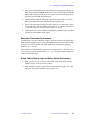
6.1 Testing RF Transmitter Performance .........................................................................
Liquids Observe Transmitter RF Signal Path ....................................................
Testing the Solids Observe Transmitter RF Signal Path ....................................
Decoupler Transmitter Performance .................................................................
Solids Cabinet Status Light and Safety Switch Performance ............................
6.2 Wideline NMR Tests ..................................................................................................
Wideline Solids Test Sample Kit .......................................................................
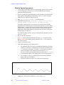
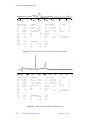
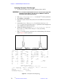
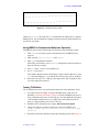
Measuring 90 Pulse and System Sensitivity ......................................................
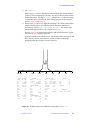
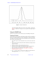
Sodium 90 Pulse and Sensitivity Measurement ................................................
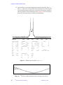
System Recovery Time ......................................................................................
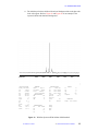
Wideline Spectral Appearance ..........................................................................
54
54
54
55
55
56
56
56
58
59
60
Chapter 7. CRAMPS/Multipulse Module Tests.............................................. 67
7.1 Tuning the High-Power (Cavity) Amplifier ...............................................................
Initial Tuning of the Cavity Amplifier (CW Mode) ..........................................
Fine Tuning the Cavity Amplifier (Pulsed Mode) .............................................
Tuning the Cavity Amplifier During Normal Operation ...................................
Adjusting the Overdrive Interlock ....................................................................
7.2 Testing RF Transmitter Performance .........................................................................
Testing the Gating ..............................................................................................
Checking Decoupler Transmitter Performance .................................................
Testing the Amplifier .........................................................................................
Adjusting Decoupler Field Strength ..................................................................
7.3 Testing CRAMPS NMR ............................................................................................
Testing Multipulse NMR ...................................................................................
Testing Basic NMR ...........................................................................................
Running the FLIPFLIP Pulse Sequence ............................................................
Running the FLIPFLOP Pulse Sequence ..........................................................
Using MREV8 to Demonstrate Multipulse Operation ......................................
Testing 1H Wideline ..........................................................................................
Testing the CRAMPS Probe ..............................................................................
68
68
69
70
70
71
72
72
73
74
75
76
76
78
80
81
81
82
Chapter 8. Solid-State Variable Temperature System .................................. 85
8.1 Installing the VT CP/MAS Pneumatics Box .............................................................
8.2 Installing the 50-Liter Dewar and Heat Exchanger ...................................................
8.3 Installing the VT Transfer Line Hanger .....................................................................
To Install the VT Hanger on Oxford Magnets ...................................................
4
UNITY
INOVA Solids Hardware Installation
01-999044-00 A0398
86
88
90
90
Table of Contents
To Install the VT Hanger on Varian Magnets with a Liquids Bucket ...............
To Install the VT Hanger on Varian Magnets without a Liquids Bucket ..........
8.4 Filling the 50-Liter Dewar .........................................................................................
8.5 Testing the Solid-State VT System ............................................................................
Refilling the 50-Liter Dewar ..............................................................................
Measuring Sample Temperature ........................................................................
91
92
92
95
98
98
Index.................................................................................................................. 99
01-999044-00 A0398
UNITY
INOVA Solids Hardware Installation
5
Table of Contents
6
UNITY
INOVA Solids Hardware Installation
01-999044-00 A0398
List of Figures
Figure 1. UNITYINOVA NMR Console with Solids Cabinet .............................................................
Figure 2. DAC Board Layout Showing Location for Rotor Sync Chip .........................................
Figure 3. VT CP/MAS Pneumatics/Tachometer Box ...................................................................
Figure 4. New Holes in the Side of the Pneumatics/Tachometer Box ...........................................
Figure 5. New Holes in Bottom of Pneumatics/Tachometer Box ..................................................
Figure 6. Rotor Speed Controller Interface Diagram ....................................................................
Figure 7. Rotor Controller Pneumatics Block Diagram ................................................................
Figure 8. Rotor Controller Connection Diagram ...........................................................................
Figure 9. Spinner Control Window ................................................................................................
Figure 10. Decoupler Field γB2 .....................................................................................................
Figure 11. Solids Cabinet Open Front View ..................................................................................
Figure 12. UNITYINOVA Spectrometer, Front and Back Views ........................................................
Figure 13. Solids Cabinet, Open Back View and the Relay Panel ................................................
Figure 14. AC Input at Rear of AMT M3000 Amplifier ...............................................................
Figure 15. High-Power Amplifier Control Panel on Solids Cabinet .............................................
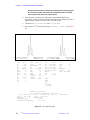
Figure 16. Sample Spectrum, S/N = 249.6, 300-MHz System ......................................................
Figure 17. Sample Sodium 90 Pulse and Sensitivity Spectrum, 300-MHz System ......................
Figure 18. System Recovery Time, Sample FID Display ..............................................................
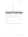
Figure 19. SSECHO FID for Malonic Acid-d6 Using lsfid ...........................................................
Figure 20. Wideline SSpectrum of Malonic Acid-d6 With compul='n' .........................................
Figure 21. Wideline Spectrum With compul='y' ...........................................................................
Figure 22. 23Na FID of Sodium Standard (NaNO3) Starting at Top of Echo ................................
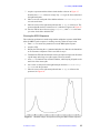
Figure 23. Wideline Spectrum With Sodium Solid Standard ........................................................
Figure 24. Sample Spectrum From a Probe With Acoustical Ringing ..........................................
Figure 25. Sample Spectrum With Sodium Background ...............................................................
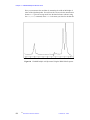
Figure 26. Sample Spectrum With Sodium And Aluminium Background ...................................
Figure 27. High-Power (Cavity) Amplifier ....................................................................................
Figure 28. High-Power Amplifier Control Panel on the Solids Cabinet ......................................
Figure 29. Decoupler Field Strength γB2 .......................................................................................
Figure 30. Standard 1H Observe Spectrum Using the S2PUL Pulse Sequence ............................
Figure 31. Receiver Recovery FID ................................................................................................
Figure 32. Real Channel FID Pattern ............................................................................................
Figure 33. FLIPFLIP FID at Exact 90 Pulse .................................................................................
Figure 34. FLIPFLOP “Tram Tracks” ...........................................................................................
Figure 35. FLIPFLOP desired FID ................................................................................................
Figure 36. Adipic Acid Spectrum ..................................................................................................
Figure 37. CRAMPS Adipic Acid Spectrum Using the MREV8 Pulse Sequence ........................
Figure 38. CRAMPS Adipic Acid Spectrum Using the BR24 Pulse Sequence ............................
Figure 39. Solid-Sate NMR VT System Configuration .................................................................
Figure 40. VT CP/MAS Pneumatics Box ......................................................................................
01-999044-00 A0398
UNITY
INOVA Solids Hardware Installation
15
21
22
25
26
26
27
28
29
42
46
48
50
51
54
57
58
59
60
61
62
62
63
64
64
65
68
71
74
76
77
78
79
80
81
82
83
84
85
87
7
List of Figures
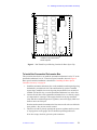
Figure 41. Approximate Orientation of Heat Exchanger Relative to The Magnet ........................
Figure 42. Standard Liquids VT Buckets Configurations .............................................................
Figure 43. VT Hanger Installation on Oxford Magnets ................................................................
Figure 44. VT Hanger Bracket Installed on a Varian Magnet .......................................................
Figure 45. Partition Valve Positions ..............................................................................................
Figure 46. Assembly for Filling the Dewar With Liquid Nitrogen ...............................................
Figure 47. Connection Diagram for Oxford VT Cable and Sorensen Power Supply ....................
88
89
90
91
93
94
96
List of Tables
Table 1. Maximum γB2 Values ......................................................................................................
Table 2. Dimensions of Complete Solids Cabinet and UNITYINOVA Cabinet ..................................
Table 3. Minimum Distances of UNITYINOVA Console from Magnet Centerline ............................
Table 4. 90 Pulse and Signal-to-Noise Specifications ..................................................................
8
UNITY
INOVA Solids Hardware Installation
01-999044-00 A0398
43
45
47
57
SAFETY PRECAUTIONS
Observe the following safety precautions during installation, operation,
maintenance, and repair of this instrument. Failure to comply with these
precautions, or with specific warnings and cautions elsewhere, violates safety
standards of design, manufacture, and intended use of the instrument. Varian
assumes no liability for customer failure to comply with these precautions.
The following warning and caution illustrate the style used in Varian manuals for safety
precaution notices and explain when each type is used:
WARNING: Warnings are used when failure to observe instructions or precautions
could result in injury or death to humans or animals, or significant
property damage.
CAUTION:
Cautions are used when failure to observe instructions could result in
permanent damage to equipment or data.
WARNINGS
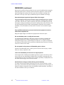
Cardiac pacemaker and metal prosthetics wearers must remain beyond the 5gauss stray fields, as shown in the table below, until safety is clearly established;
for example, remain more than 4.6 meters (15 feet) from 600-MHz magnet.
The magnet system generates strong magnetic and electromagnetic fields that can
affect operation of some cardiac pacemakers or harm a metal prosthesis. Pacemaker
wearers should consult the user manual provided by the pacemaker manufacturer or
contact the pacemaker manufacturer to determine the effect on a specific pacemaker.
Pacemaker wearers should always notify their physician and discuss the health risks of
being in proximity to magnetic fields. Wearers of metal prosthetics should contact their
physician to determine if a danger exists. The following table may help determine the
effect of a system on pacemakers or a metal prosthesis. The table shows the radial
(horizontal) and axial (vertical) extent of a 5-gauss-level stray magnetic field as
measured from the center of the magnet:
Proton Frequency
(MHz)
Bore
(mm)
Radial Extent
(m)
Axial Extent
(m)
200
51
1.5
1.5
200
89
2.0
2.0
300
51
1.7
1.7
300
89
2.2
2.8
400
54
2.2
2.8
400
89
3.0
3.8
500
51
2.8
3.6
600
51
3.7
4.6
750
51
6.1
7.6
01-999044-00 A0398
UNITY
INOVA Solids Hardware Installation
9
SAFETY PRECAUTIONS
WARNINGS (continued)
Refer to the Installation Planning Guide for your system for additional stray magnetic
field plots and the effect of the stray field on electronic equipment. Varian provides
signs containing this warning with each system. Post the signs according to the
directions on the sign. Upon request, additional signs are available at no charge.
Keep metal objects beyond the 5-gauss field of the magnet.
The strong magnetic field of the dewar attracts objects containing steel, iron, or other
“magnetic” materials, such as tools, electronic equipment, compressed gas cylinders,
steel chairs, and steel carts. Unless restrained, such objects can suddenly fly towards
the magnet, causing personal injury and extensive damage to the probe, the dewar, and
the superconducting solenoid. Only nonferromagnetic materials (such as plastics,
aluminum, wood, and stainless steel) should be used in the area around the magnet
dewar.
Only qualified maintenance personnel shall remove equipment covers or
make internal adjustments.
Dangerous high voltages exist inside the equipment that can kill or injure.
Do not substitute parts or modify the instrument.
Any unauthorized modification could injure personnel or damage equipment and
potentially terminate the warrantee agreements and/or service contract. Written
authorization approved by a product manger of Varian, Inc. is required to implement
any changes to the hardware of the spectrometer. Maintain safety features by referring
service to a Varian service office.
Do not operate in the presence of flammable gases or fumes.
Operation with flammable gases or fumes present creates the risk of injury or death
from toxic fumes, explosion, or fire.
Leave area immediately in the event of a magnet quench.
If the magnet dewar should quench (sudden appearance of gasses from the top of the
dewar), leave the area immediately. Sudden release of helium or nitrogen gases can
rapidly displace oxygen in an enclosed space creating a possibility of asphyxiation. Do
not return until the oxygen level returns to normal.
Avoid helium or nitrogen contact with any part of the body.
In contact with the body, helium and nitrogen can cause an injury similar to a burn.
Never place your head over the helium and nitrogen exit tubes on top of the magnet. If
helium or nitrogen contacts the body, seek immediate medical attention, especially if
the skin is blistered or the eyes are affected.
10
UNITY
INOVA Solids Hardware Installation
01-999044-00 A0398
SAFETY PRECAUTIONS
WARNINGS (continued)
On magnets with removable quench tubes, keep the tubes in place except
during helium servicing.
Varian 200- and 300-MHz standard bore (51 mm) superconducting magnets include
removable helium vent tubes. If the magnet dewar should quench (sudden appearance
of gasses from the top of the dewar) and the vent tubes are not in place, the helium gas
would be partially vented sideways, possibly injuring the skin and eyes of personnel
beside the magnet. During helium servicing, when the tubes must be removed, follow
carefully the instructions and safety precautions given in the Varian Magnet
Installation and Maintenance Manual.
Do not look down the upper barrel.
Unless the probe is removed from the magnet, never look down the upper barrel. You
could be injured by the sample tube as it ejects pneumatically from the probe. We
recommend that you always wear safety glasses when working with the probe.
Do not exceed the boiling or freezing point of a sample during variable
temperature experiments.
A sample tube subjected to a change in temperature can build up excessive pressure,
which can break the sample tube glass and cause injury by flying glass and toxic
materials. To avoid this hazard, establish the freezing and boiling point of a sample
before doing a variable temperature experiment.
Support the magnet and prevent it from tipping over.
The magnet dewar has a high center of gravity and could tip over in an earthquake or
after being struck by a large object, injuring personnel and causing sudden, dangerous
release of nitrogen and helium gases from the dewar. To prevent tip-over, either bolt the
magnet to the floor or support the magnet from the ceiling with ropes. Refer to the
Installation Planning Guide for your system.
Solids equipment such as CRAMPS and CP/MAS require high pneumatic
pressures.
Fittings must be secure. Wear safety glasses when working around the probe. Follow
the warnings about maximum spin rates for particular rotors.
01-999044-00 A0398
UNITY
INOVA Solids Hardware Installation
11
SAFETY PRECAUTIONS
CAUTIONS
Prevent the sample tube from breaking.
The top of the sample tube can break off when the probe is removed. It is best to eject
the sample before removing the probe from the magnet. Otherwise, use extreme
caution when removing the probe if the sample is still in the probe.
Keep magnetic tapes, credit cards, and watches away from the magnet
dewar.
Most cards, such as ATM cards, credit cards, and some new drivers licenses, contain a
strip of magnetic media that can be damaged by a strong magnetic field. Many wrist
and pocket watches are also susceptible to damage from intense magnetism.
Check helium and nitrogen gas flowmeters daily.
Record the readings to establish the operating level. The readings will vary somewhat
because of changes in barometric pressure from weather fronts. If the readings for
either gas should change abruptly, contact qualified maintenance personnel. Failure to
correct the cause of abnormal readings could result in extensive equipment damage.
Do not remove the relief valves on the vent tubes.
The relief valves prevent air from entering the nitrogen and helium vent tubes. Air that
enters the magnet will contain moisture that can freeze, causing blockage of the vent
tubes and possibly extensive damage to the magnet. Except when transferring nitrogen
or helium, be certain that the relief valves are secured on the vent tubes.
Never operate high-power amplifiers with liquids probes.
On systems with high-power amplifiers for solids or microimaging, never operate the
amplifiers with a liquids probe. The high power available from these amplifiers will
destroy liquids probes. Use the appropriate high-power probe with the high-power
amplifier.
Radio-Frequency Emission Regulations
The covers on the instrument form a barrier to radio-frequency (rf) energy. Removing
any of the covers or modifying the instrument may lead to increased susceptibility to
rf interference within the instrument and may increase the rf energy transmitted by the
instrument in violation of regulations covering rf emissions. It is the operator’s
responsibility to maintain the instrument in a condition that does not violate rf emission
requirements.
12
UNITY
INOVA Solids Hardware Installation
01-999044-00 A0398
Introduction
This manual describes the procedures used for installing and testing the following
solids modules on UNITYINOVA NMR spectrometers:
• Rotor Synchronization Accessory
• CP/MAS Solids Module
• Wideline Solids Module
• CRAMPS/Multipulse Solids Module
Other Applicable Manuals
Procedures for installing and tuning solids probes are contained in the NMR Probes
Installation manual.
Information for operating solids systems is contained in the User Guide: Solid-State
NMR.
For solids systems schematics, see the publication UNITYINOVA Solids Schematics.
Conventions Used in the Manual
The following notational conventions are used throughout all VNMR manuals:
• Characters in courier (typwriter-like characters) are used for UNIX or VNMR
commands, parameters, directories, and file names in the text of the manual; for
example:
The shutdown command is in the /etc directory.
• Characters in courier are also used to show screen output; for example:
Self test completed successfully
• Italic characters are used for text displayed on the screen that is not the same every
time; for example,
Abort at some_address
means the value of some_address depends upon when the abort command is
made—what you might see on the screen is a message like this:
Abort at 47F82
• Because pressing the Return key is required at the end of almost every command
or line of text you type on the keyboard, use of the Return key is mentioned only
in cases where it is not used. This convention avoids repeating the instruction
“press the Return key” throughout most of this manual.
Except for a few commands entered from UNIX, the commands in this manual are
invoked in the VNMR window environment. Although some VNMR commands (such
as echo and vi) have the same name as UNIX commands, the VNMR and UNIX
syntax is always different.
87-195482-00 A0297
UNITY
INOVA Solids Hardware Installation
13
Introduction
14
UNITY
INOVA Solids Hardware Installation
87-195482-00 A0297
Chapter 1.
Getting Started
This manual describes the procedures used for installing and testing the following
solids modules on UNITYINOVA NMR spectrometers:
• Rotor Synchronization Accessory
• CP/MAS Solids Module
• Wideline Solids Module
• CRAMPS/Multipulse Solids Module
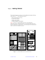
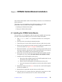
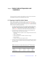
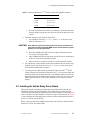
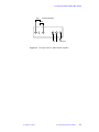
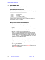
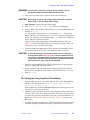
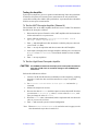
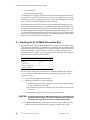
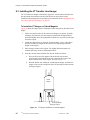
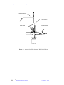
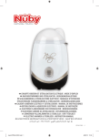
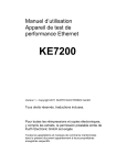
Figure 1 shows the UNITYINOVA NMR console next to the solids cabinet.
This chapter provides information about how to proceed through this manual for
different combinations of solids hardware. Also in this chapter is information about
what to do before the installation is started.
320
620
620
Figure 1.
01-999044-00 A0398
INOVA NMR Console with Solids Cabinet
UNITY
UNITY
INOVA Solids Hardware Installation
15
Chapter 1. Getting Started
1.1 Solids Modules Installation Guide
Listed below are the chapters in this manual that guide you in installing the different
solids modules. Work through the chapters, in the order listed, under the solids module
you want to install.
Rotor Synchronization and Rotor Speed Controller Accessory
• Complete all of Chapter 2, “Rotor Synchronization and Rotor Speed Controller
Installation,” on page 19.
CP/MAS Module
• Complete all of Chapter 2, “Rotor Synchronization and Rotor Speed Controller
Installation,” on page 19.
• Complete all of Chapter 4, “CP/MAS Solids Module Installation,” on page 39.
Wideline Module
• Complete all of Chapter 3, “Wideband NMR Module,” on page 35
• Complete all of Chapter 5, “Solids Cabinet Preparation and Installation,” on page
45.
• Complete all of Chapter 6, “Wideline Module Tests,” on page 53.
CRAMPS/Multipulse Module
• Complete all of Chapter 2, “Rotor Synchronization and Rotor Speed Controller
Installation,” on page 19.
• Complete all of Chapter 3, “Wideband NMR Module,” on page 35
• Complete all of Chapter 5, “Solids Cabinet Preparation and Installation,” on page
45.
• Complete all of Chapter 7, “CRAMPS/Multipulse Module Tests,” on page 67.
Complete Solids Module
• Complete all of Chapter 2, “Rotor Synchronization and Rotor Speed Controller
Installation,” on page 19.
• Complete all of Chapter 3, “Wideband NMR Module,” on page 35
• Complete all of Chapter 5, “Solids Cabinet Preparation and Installation,” on page
45.
• Complete all of Chapter 6, “Wideline Module Tests,” on page 53.
• Complete all of Chapter 7, “CRAMPS/Multipulse Module Tests,” on page 67.
16
UNITY
INOVA Solids Hardware Installation
01-999044-00 A0398
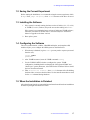
1.2 Saving the Current Experiment
1.2 Saving the Current Experiment
Before starting the installation, we recommend saving the current experiment, which
is exp1. Enter jexp1 svf(file), where file is the name of the file to be saved.
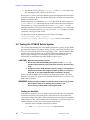
1.3 Installing the Software
1. If the system is currently running the latest version of Solaris (2.4 , 2.5, or 2.6)
or VNMR (5.2 or 6.1) software, skip to the next section and log in as vnmr1.
If the system is not running the latest versions of Solaris and VNMR software,
follow the procedures in VNMR, Solaris, and SunOS Software Installation
Manual to upgrade to the latest versions.
2. Boot up the system.
1.4 Configuring the Software
The rotor synchronization, wideline, CRAMPS/multipulse, and complete solids
modules require you to configure the NMR system as described below.
1. When bootup is finished, log in as vnmr1 (you may need to request a password
from the user):
login: vnmr1
password:
2. After VNMR has started, enter the VNMR command config.
3. Use the VNMR CONFIG window to configure the system. VNMR
configuration, including details on changing the “Max Spectral Width” and
“Rotor Sync” system parameters, is described in the VNMR and Solaris SunOS
Software Installation manual.
4. Enter rts(file) su load='n', where file is the name of the file holding
the shim values, to retrieve the shim values. Use the same file name that was used
for the svf command during shutdown.
1.5 When the Installation is Finished
All replaced items from the system and all unused items from the hardware installation
kit must be packaged and returned to Varian.
01-999044-00 A0398
UNITY
INOVA Solids Hardware Installation
17
Chapter 1. Getting Started
18
UNITY
INOVA Solids Hardware Installation
01-999044-00 A0398
Chapter 2.
Rotor Synchronization and
Rotor Speed Controller Installation
This chapter provides instructions for installing the rotor synchronization and rotor
speed controller hardware on a UNITYINOVA NMR spectrometer system. The rotor
synchronization and rotor speed controller accessory (01903728-00) consists of the
following:
• Rotor synchronization accessory (01-903729-00)
• Rotor speed controller accessory (01-903732-00)
The rotor synchronization accessory provides access to three additional pulse sequence
elements: xgate, rotorsync, and rotorperiod. These elements are used to
synchronize pulses and delays with the tachometer signal of the pneumatics/
tachometer box.
The rotor speed controller accessory provides computer control and stabilization of the
spin rate of a CP/MAS sample. Software is built into the Magnet Sample Regulation
(MSR) board and is controlled through the spinner command in VNMR.
Both of these accessories require a pneumatics/tachometer box. The rotor
synchronization accessory requires one of the following:
• Pneumatics/tachometer box for VT (00-992090-01)
• Pneumatics/tachometer box for VT and rotor speed controller (01-903863-00)
• Pneumatics/tachometer box for VT that is upgraded with the rotor speed controller
upgrade kit (01-903862-00)
The rotor speed controller accessory requires one of the following:
• Pneumatics/tachometer box for VT and rotor speed controller (01-903863-00)
• Pneumatics/tachometer box for VT that is upgraded with the rotor speed controller
upgrade kit (01-903862-00)
01-999044-00 A0398
UNITY
INOVA Solids Hardware Installation
19
Chapter 2. Rotor Synchronization and Rotor Speed Controller Installation
2.1 Installing the Rotor Synchronization Accessory
This section describes how to install the rotor synchronization accessory. Please read
the following cautions before beginning the installation.
CAUTION:
Use only dry nitrogen (N2) for variable temperature work.
While working near the magnet, prevent tools and other hardware from
being drawn into the magnet bore. Plug the magnet bore and use
nonmagnetic tools.
To prevent damage to the boards and components from electrostatic
discharge, wear a grounded wrist strap while handling printed circuit.
boards
The rotor synchronization accessory consists of the following:
• Rotor sync FPGA chip (Part No. 01-903362-01)
• Pneumatics/tachometer box for VT with mounting hardware
• Pneumatics/tachometer box power supply
• Control and power cable
The accessory works with Varian high-speed CP/MAS probes and Doty probes that
have an optical tachometer. The accessory does not work correctly with Doty probes
that have a triboelectric tachometer.
Doty probes must have the following additional hardware:
• Tachometer amplifier
• Tachometer cable, probe to amplifier
• Tachometer amplifier power supply
• BNC cable, tachometer amplifier to pneumatics/tachometer box EXTERNAL
INPUT
The following procedures describe how to install the rotor synchronization accessory
hardware.
To Install the Rotor Synchronization FPGA Chip
1. Power down the UNITYINOVA console. Follow the shutdown procedures in the
User Guide: Solid-State NMR.
2. Remove the cables from the DAC (Data Acquisition Controller) board.
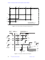
3. After placing a grounding strap on your wrist, remove the DAC board.
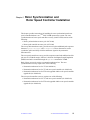
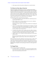
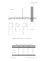
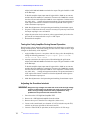
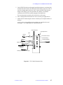
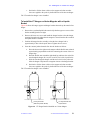
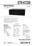
4. Insert the rotor synchronization FPGA chip into socket U12T of the DAC board.
Make sure the chamfered corner of thee chip matches the chamfered corner of
the socket and board silkscreen. See Figure 2.
5. Insert the DAC board into the card cage.
6. Reconnect the cables from to the DAC board using the cable labels as a
reference.
7. Turn on the power to the UNITYINOVA console.
20
UNITY
INOVA Solids Hardware Installation
01-999044-00 A0398
2.1 Installing the Rotor Synchronization Accessory
1
2
3
4
5
6
7
8
9
10
11
12
13
14
15
16
TEST
BENCH FINAL
A
B
C
C
D
D
E
E
F
F
G
G
H
H
J
J
K
K
L
L
M
M
N
N
P
P
R
R
U12T
B
S
S
T
T
U
1
17
A
U
2
3
4
5
6
7
8
9
10
11
12
13
14
15
16
17
Install Rotor Synchronization
FPGA chip here
Figure 2. DAC Board Layout Showing Location for Rotor Sync Chip
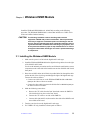
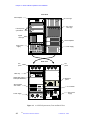
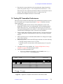
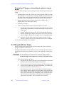
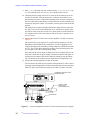
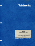
To Install the Pneumatics/Tachometer Box
This procedure describes how to install the pneumatics/tachometer box for VT or the
pneumatics/tachometer box for VT and rotor speed controller, shown in Figure 3.
Rotor speed controller installation is described in “Installing the Rotor Speed
Controller Accessory” on page 24.
1. Install the pneumatics/tachometer box on the standard (round) magnet leg using
the hardware provided in the kit. If the antivibration leg system is installed
(square legs), install the box on the leg using the pneumatics box mount kit if
available (01-901479-00), or rest the pneumatics/tachometer box on the floor.
2. Connect the inlet hose of the pneumatics/tachometer box to a clean dry supply
of compressed air or nitrogen. This supply should be at 90 psig continuous.
Close both drive and bearing pressure regulators, turn on the supply. Make sure
the flow meters are full open.
Note that under normal circumstances the flow meter needle valves are left in the
open position—they are not used for control.
3. Check for air leaks by slowly opening both pressure regulators until a pressure
of 10 psig shows on the gauges. No air should escape through the hoses.
If air does escape, check for grit in the probe connectors.
01-999044-00 A0398
UNITY
INOVA Solids Hardware Installation
21
Chapter 2. Rotor Synchronization and Rotor Speed Controller Installation
Flow meter/valve
Angle adjust tool
Filter
Tachometer display
Drive to probe
Drive pressure
regulator and gauge
Bearing to probe
N2 supply in
Rotation trigger adjust
Body N2 to probe
Bearing pressure
regulator and gauge
To eject port
of magnet
Purge to heat exchanger
Body pressure
regulator and gauge
Sockets for optical
fibers from probe
BNC connector for Doty
probe tach preamp (J6007)
Figure 3. VT CP/MAS Pneumatics/Tachometer Box
When this test is finished, close both regulators.
4. Open the check valve of the air connector on each hose from the pneumatics/
tachometer box to the probe. This is done by inserting a thin tool (such as a small
flat-head screwdriver) into the connector and pressing down until it clicks. Turn
the bearing regulator to show 10 psig. The flow meter should show a good flow
rate. If not, check that the valve on the flow meter is in the full open position.
Repeat this step for the drive supply.
5. Install the pneumatics/tachometer box power supply in the back of the rf cabinet,
or another convenient location
6. Plug the supply cord from the pneumatics/tachometer box power supply into the
110 Vac outlet at the rear of the system power supply.
7. Install the cable from the power supply to the pneumatics/tachometer box,
routing it with the other cables running to the magnet. Lead the coax terminated
with a SMB connector through the cabinet to the front of the digital card cage.
8. Plug the SMB connector into the J2 at the EXT TIME BASE position.
9. Turn on the power and make sure that power is supplied to the pneumatics/
tachometer box by checking for light from the optical connector of the
pneumatics/tachometer box. The LCD display on the pneumatics/tachometer
box should also display a decimal point.
10. Connect a CP/MAS probe to the pneumatics/tachometer box drive and bearing
hoses.
22
UNITY
INOVA Solids Hardware Installation
01-999044-00 A0398
2.1 Installing the Rotor Synchronization Accessory
11. Connect the body nitrogen air hose to the probe and adjust to 20 lpm. for VT
operation.
For VT operation, clean and dry body nitrogen (20 lpm) is required. For ambient
operation, 5 to 20 lpm body air is recommended.
12. For Doty probes only:
a.
Connect the Doty tachometer amplifier OPTICAL OUTPUT position to
the pneumatics/tachometer box EXTERNAL INPUT.
b.
Plug the power supply of the tachometer amplifier into a source of 110
Vac.
c.
Move the switch on the tachometer amplifier marked OPTICAL OFF to
the position away from its label.
d. On the pneumatics/tachometer box, set the 3-position switch, near the
external input, to EXT NEG or EXT POS.
13. For Varian VT CP/MAS probes only:
a.
Connect the optical lines to the fiber optic lines of the probe to the sockets
on the pneumatics/tachometer box.
b.
Set the 3-position switch near the external input to VA OPTIC.
To Replace the Air/Gas Filter
Replace the blue disposable 0.6 micron particle filter (Part No. 27-180354-00) after it has
become discolored (turned red).
1.
Disconnect the filter by pressing the movable sleeve on the gas hose fitting toward
the tube fitting (you may need a small crescent wrench) and pulling the filter out of
the tube fitting.
2.
Insert a new filter, with the arrow on the filter pointing towards the probe.
3.
Return the movable sleeve to its original position.
01-999044-00 A0398
UNITY
INOVA Solids Hardware Installation
23
Chapter 2. Rotor Synchronization and Rotor Speed Controller Installation
2.2 Installing the Rotor Speed Controller Accessory
This section describes how to install the rotor speed controller accessory. The rotor
speed controller accessory consists of the following:
• Pneumatics/tachometer box for VT and rotor speed controller (01-903863-00) or
a pneumatics/tachometer box that has been modified with the rotor speed
controller upgrade kit (01-903862-00).
• Cable to the UNITYINOVA console breakout panel.
• Cable from the Breakout Panel to the Magnet-Sample Regulation (MSR) board.
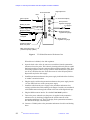
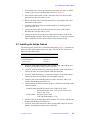
To Upgrade the Pneumatics/Tachometer Box
This procedure describes how to modify the pneumatic/tachometer box by installing
the plumbing, the wiring, and the two valves from the upgrade kit.
If you are installing a previously modified pneumatic/tachometer box, or if you are
using the pneumatics/tachometer box for VT and rotor speed controller, first follow the
procedure “To Install the Pneumatics/Tachometer Box” on page 21, and then skip to
step 18 on page 27.
1. Disconnect the pneumatic/tachometer box from the system. Remove the rear
cover from the pneumatic/tachometer box.
2. Remove the tubing elbow from the input side of the drive pressure regulator,
located near the top of the pneumatic/tachometer box, and replace the elbow
with the swivel tee from the kit. To release the tubing from the fitting, push the
plastic gray ring toward the fitting
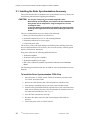
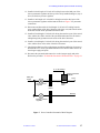
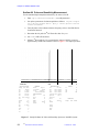
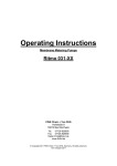
3. Make new holes in the pneumatic/tachometer box housing as follows:
a.
Make two holes in the side of the housing, below the Body Pressure
regulator, as shown in Figure 4.
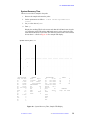
b.
Make six holes in the bottom of the housing, as shown in Figure 5. If weld
studs are present on the bottom wall of the housing, punch or drill them
out before creating the new holes.
4. On the electro-pneumatic regulator, install the tubing elbow, previously removed
from the Drive Pressure regulator, into the SUP port. Use Teflon pipe tape to seal
the treads of all tube fittings installed during this procedure. Install the 1/4-inch
tube elbow into the OUT port. Plug the G port of the electro-pneumatic regulator.
5. Remove the black plastic cover, wire entry nut, metal washer, and rubber spacer
from the electro-pneumatic regulator. Cut the rubber spacer and wrap it around
the BRN, ORN, and RED wires from the cable harness. Thread the BRN, ORN,
and RED wires through the wire entry nut and cable hole in the side of the
housing. Replace the cover and secure it using the original two screws and Orings.
6. Mount the electro-pneumatic regulator on the bottom wall of the housing using
the screws and washers provided in the kit. The inlet port and cable hole of the
regulator mount nearest the side wall of the housing.
7. Install connector J3 of the cable harness into the new hole in the side of the
housing. Mount the BNC connector in the new hole above J3. Place short lengths
of shrink tubing over the short YEL and GRN wires of the harness. Solder the
24
UNITY
INOVA Solids Hardware Installation
01-999044-00 A0398
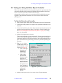
2.2 Installing the Rotor Speed Controller Accessory
short YEL wire to the center conductor and the GRN wire to the outer conductor
of the BNC connector according to the diagram in Figure 6. Cover the solder
joints on the connector with shrink tubing and shrink it with a heat gun or hair
dryer.
8. Connect the longer YEL wire to terminal 4and the GRN wire to terminals 3 of
the tachometer. Replace the terminal screws on the tachometer with the new
screws provided in the kit—these are longer than the originals.
9. Install tube elbows in the SUP and OUT ports of the control valve.
10. Mount the control valve to the bottom of the housing—using metric screws and
spring and flat washers—in the two newly created holes (0.120 dia). Orient the
OUT port of the control valve away from the electro-pneumatic regulator
previously installed.
11. Check that the EXH (exhaust) port is free and clear. If this port is sealed with a
set screw, remove the screw.
Body pressure
(existing hole)
7.00
0.505
0.218
J4
4.50
Tach
test point
0.130
0.04
0.065
0.53
J3
2.25
0.41
Rotor
control
0.81
0.0
0.0
4.40
3.37
New holes in side
of pneumatics/tachometer box
(Dimensions are in inches)
0.0
Figure 4. New Holes in the Side of the Pneumatics/Tachometer Box
01-999044-00 A0398
UNITY
INOVA Solids Hardware Installation
25
Chapter 2. Rotor Synchronization and Rotor Speed Controller Installation
1.612
0.0
2.478
4.35
5.77
2.76
0.196 dia
0.196 dia
0.196 dia
0.196 dia
1.340
0.120 dia
.666
0.800
0.120 dia
New holes in bottom
of pneumatics/tachometer box
(Dimensions are in inches)
0.0
Figure 5. New Holes in Bottom of Pneumatics/Tachometer Box
MSR board
J/P12
Rotor speed control
pneumatics/tachometer box
J/P8284
Breakout Panel
J/P3
Cable
(00-993841-00)
14 &16
5
5
1
Cable
(00-993783-00)
BRN
A
DAC out
0–5 Vdc
Electro-pneumatic
regulator
3
AGND
0.01 µF
15
4
4
4
11 & 12
9
9
2
13
8
8
5
7 & 8 & 10
2
2
3
ORN
BLK
2
1
DC in
0–5 Vdc
+12V in
A
+12 V
out
RED
3
GND
3
1
9
1
1
6
CP/MAS
tachometer board
J2
GRN
D
Rotor
spin pulse
Tachometer
YEL
4
RED
Signal in
J4
YEL
Tachometer
test point
Existing cable
(00-992109-00)
GRN
Figure 6. Rotor Speed Controller Interface Diagram
26
UNITY
INOVA Solids Hardware Installation
+5 V
out
01-999044-00 A0398
Rotor
2 signal
out
1 GND
2.2 Installing the Rotor Speed Controller Accessory
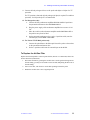
12. Install a 26-inch length of 3/8-inch O.D. tubing between the SUP port of the
electro-pneumatic regulator and the top of the newly installed tubing tee (step 2
above) at the drive pressure regulator.
13. Install a 9-inch length of 1/4-inch O.D. tubing between the OUT port of the
electro-pneumatic regulator and the Drive air. Refer to Figure 7 for pneumatic
connections.
14. Disconnect and discard the 26-inch length of 1/4-inch O.D. tubing from the
upper (outlet) fitting of the drive flowmeter (the upper one) and from the union
at the filter outside of the pneumatic/tachometer box.
15. Install a 45-inch length of 1/4-inch O.D. tubing between the A port of the control
valve and the drive filter outside of the pneumatic/tachometer box. Route the
tubing through the grommet near the outlet of the drive flowmeter.
16. Install a 19-inch length of 1/4-inch O.D. tubing between the P port of the control
valve and the elbow at the outlet of the drive flowmeter.
17. Check the installations of the wiring harness and tubing and fittings for accuracy.
Reinstall the cover on the pneumatic/tachometer box and reconnect the box to
the nitrogen supply and probe.
18. Reconnect the pneumatic/tachometer box to the nitrogen supply and probe.
Refer to the procedure “To Install the Pneumatics/Tachometer Box” on page 21.
0 – 5 Vdc Control
Electro-pneumatic
regulator
Main gas
supply
Drive
Supply
Out
Control
valve
Drive pressure
regulator
Flow
meters
Bearing
Bearing pressure
regulator
Figure 7. Rotor Controller Pneumatics Block Diagram
01-999044-00 A0398
UNITY
INOVA Solids Hardware Installation
27
Chapter 2. Rotor Synchronization and Rotor Speed Controller Installation
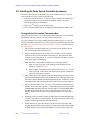
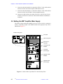
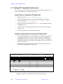
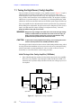
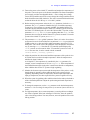
To Connect the Cables
This procedure describes how to connect the cables associated with the rotor speed
controller accessory. Use Figure 8 as a guide during the following procedure.
1. Power down the UNITYINOVA console. Follow the shutdown procedures in the
User Guide: Solid-State NMR.
2. Partially remove the MSR board from the digital card cage.
3. Plug the ribbon cable end of the cable into J12 on the MSR board.
4. Reseat the MSR board.
5. Run the D-shell end of the cable 01-903730-00 along the lower front of the
digital card cage to the left cable access.
6. From the rear of the console, get the D-shell end and run it to the hole for J8242
to the left (from the back of the Breakout panel). Punch out the hole cover if
necessary. Fasten the connector to the Breakout panel with the bolts provided.
7. Connect the cable 00-993841-00 to J3 of the pneumatic/tachometer box and to
the newly installed J8242.
8. Turn on the power to the UNITYINOVA console.
Bearing and
drive air to
probe
Rotation trigger
adjust
From source
gas supply
J4
Power input (J1)
Tach test port
J8242 on the
Breakout panel
J3
Console
top view
MSR board
Ribbon
cable
Console front
Digital
card cage
top view
Figure 8. Rotor Controller Connection Diagram
28
UNITY
INOVA Solids Hardware Installation
01-999044-00 A0398
2.3 Testing and Using the Rotor Speed Controller
2.3 Testing and Using the Rotor Speed Controller
This section provides instructions for testing and using the rotor speed controller. The
rotor speed controller can be operated with spinning speed regulation (closed-loop
mode) or with a specific airflow setting (open-loop mode).
Alternatively, the air flow can be set to a maximum (65535) and the drive-pressure
regulator on the pneumatics/tachometer box can be used for manual control the
spinning speed.
To Start the Rotor Speed Controller
1. Place a painted, good quality, empty, silicon nitride rotor in the CP/MAS probe.
2. Connect the bearing and drive air supplies of the pneumatics/tachometer box to
the probe.
3. Connect the black fiber optic cable to the pneumatics/tachometer box (lower left
panel) and set the toggle switch below to V.A. for the Varian CP/MAS probe.
See “To Use Rotor Speed Control with a Doty Probe” on page 31, if a Doty
probe is to be installed.
4. Adjust the bearing pressure to 30 psig.
The rotor should begin to spin at about 200 Hz. If speeds greater than 5000 Hz
will be desired, the bearing pressure will have to be set higher than 30 psig.
Consult the NMR Probes Installation manual or the test data supplied with the
probe to determine the proper bearing pressure for a particular spinning speed
and probe.
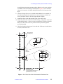
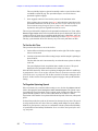
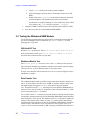
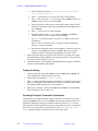
5. Enter spinner in the
VNMR input window to
open the Spinner Control
window (see Figure 9).
a.
Click on the High
Speed Spinner
(Solids Style)
control button.
c.
Click the Set
spinner airflow
instead of speed,
adjust the two
slider bars to zero,
and click the Turn
Spinner Off button.
The spinner is now
in an unregulated
or open loop mode
in which the
airflow is set
directly.
Figure 9. Spinner Control Window
6. Adjust the drive pressure slowly to a value of 60 or 70 psig maximum.
01-999044-00 A0398
UNITY
INOVA Solids Hardware Installation
29
Chapter 2. Rotor Synchronization and Rotor Speed Controller Installation
The rotor initially begins to spin and eventually reaches a speed of about 3000
to 6000 Hz at about 40 psig. The speed then drops to zero as the electropneumatic regulator engages.
7. Once engaged, continue to increase the pressure to the maximum value.
If the regulator does not engage repeat step 5 and recheck the connections to the
pneumatics/tachometer box. In any event, do not let a rotor and end cap exceed
their maximum rating during this process. Steps 6 and 7 must be repeated
anytime the drive-pressure regulator has been set to zero.
The rotor speed should be displayed on the pneumatics/tachometer box. If not, adjust
Rotation Trigger Adjust on the lower left panel until the speed is displayed. If the speed
cannot be observed, check the rotor painting and the fiber optic connections. Also, one
can observe the tachometer pulses with an oscilloscope at J4 (see Figure 8 on page 28).
The duty cycle should be about 50% but may vary if the rotor paint has worn thin.
To Set the Air Flow
This procedure describes how to set the air flow
1. Set the airflow to 1000 by moving the slider bar to the right. The air flow engages
after several seconds.
2. Continue to increment the air flow setting in steps until the sample is spinning at
about 2500 Hz.
The fine slider bar can be incremented by one when the mouse pointer is clicked
in the bar.
The speed displayed in the Acquisition Status window is correct. The speed
displayed on the pneumatics/tachometer box tends to be slower.
Move the slider bar slowly. If the rotor is spinning, changing the air flow in small steps
is good practice. Never set an air flow value that causes a speed that exceeds the rated
speed of the rotor, cap and probe. The air flow can also be set before setting the drive
pressure. In this case the electro-pneumatic regulator engages at the specified airflow
setting.
To Regulate Spinning Speed
If the rotor checks out, return the airflow setting to zero, click on Turn Spinner Off and
click to disengage the button Set Spinner Airflow Instead of Speed. The spinner is now
in regulation or closed-loop mode. Enter a spinner speed of 2500 on the slider bars. The
spinner should regulate to 2Hz or better within about 30 seconds to 1 minute.
Experiment with a number of set points within the rated speeds of the rotor, endcap and
probe.
In closed-loop mode, the speed can be increased or decreased by any value. The speed
is safely ramped to the new value. However, making small changes in speed (1000 to
2000 Hz) is good practice, until you are comfortable with the operation and reliability
of a particular rotor and endcap combination. Never exceed the rated speed of the rotor,
cap, and probe.
30
UNITY
INOVA Solids Hardware Installation
01-999044-00 A0398
2.3 Testing and Using the Rotor Speed Controller
To Manually Control the Spinner
This procedure describes how to manually control the spinner with the drive-pressure
regulator.
1. Start the rotor speed controller as described in the procedure “To Start the Rotor
Speed Controller” on page 29.
2. Set the drive-pressure regulator to zero and move the slider bars fully to the right
to set a value of 65535. Slowly adjust the spin speed to the desired value by
increasing the drive-pressure regulator.
Under manual control or with an airflow setting the spinning speed will typically drop
by about 100 to 300 Hz over five to ten minutes (due to heating of the bearings) and
then stabilize.
To Regulate Spinning Speed within VNMR
This procedure describes how to regulate spinning speed with VNMR input window.
1. Start the rotor speed controller as described in the procedure “To Start the Rotor
Speed Controller” on page 29.
2. Click on the button next to Allow spin control in experiment with go.
This button disables the speed in the Spinner Control window and transfers spin
rate control to the spin parameter in VNMR.
3. Set up a typical solids experiment, set the value of spin to the desired speed,
and enter go.
The spinner regulates at the value of spin. Include a preacquisition delay pad
to give the spinner time to stabilize. The parameter spin can be included in an
array to obtain multiple spin rates in a single experiment. In an array of spin,
the preacquisition delay is applied before each FID.
4. After the experiment is complete, click next to Allow spin control in experiment
with go to return control to the Spinner Control window.
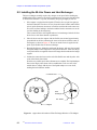
To Use Rotor Speed Control with a Doty Probe
Using the rotor speed controller with a Doty probe is similar to that with a Varian
probe. Consult the manual from Doty Scientific for the required bearing and drive
pressures. Regulation of 2 Hz may or may not be attainable, but experience to date
suggests that operation with a supersonic probe is similar to that with a Varian probe.
Be sure to use a well-painted supersonic rotor. If in doubt, consult Varian for any
specific recommendations and procedures before proceeding.
1. Connect the drive and bearing lines to the probe.
2. Connect the multi-pin cable between the probe and the small, blue spin-rate
tachometer box that is supplied with the probe.
3. Connect a BNC cable between spin-rate tachometer box and the BNC connector
on the lower left panel of the pneumatics/tachometer box.
4. Set the toggle switch on the pneumatics/tachometer box to one of the two EXT
connections.
01-999044-00 A0398
UNITY
INOVA Solids Hardware Installation
31
Chapter 2. Rotor Synchronization and Rotor Speed Controller Installation
5. Set the toggle switch on the spin-rate tachometer box to optical detection.
To Calibrate the Rotor Speed Controller
The electro-pneumatic regulator has two set screws, accessible from the sliding
window, for adjusting the zero and the span of the pressure output. The zero of electropneumatic regulator may need calibration if the rotor continues to spin (at an airflow
setting of zero) with zero bearing pressure. A small amount of bearing air is shunted to
the drive stream in the stator, causing a minimum speed that depends on the bearing
pressure. However, the drive should provide no airflow when set to zero. Also, it may
be necessary to adjust the span if the maximum rotor speed can not be obtained, or to
limit the maximum speed. Use the following steps for the calibration:
Repeating this procedure several times may be necessary.
1. Use a painted, good quality, empty, silicon nitride rotor. Install the probe and
rotor and set the airflow to zero.
2. With a bearing pressure of 30 psig, adjust the zero set screw for a minimum
sample spinning rate (usually about 200 Hz).
The electro-pneumatic regulator responds slowly so allow time for settling after
each change.
3. After the zero is adjusted, briefly turn the bearing-pressure regulator to zero with
the drive pressure engaged. The speed should fall to zero. If it does not, quickly
return the bearing pressure to 30 psig and repeat the adjustment. Do not leave
the rotor spinning with no bearing pressure.
4. To adjust the span, while the rotor is spinning, increase the airflow setting in a
series of steps of 5000 or less until either the maximum airflow setting of 65535
is obtained or until the maximum rated speed of the probe is obtained.
5. Adjust the span set screw to obtain the maximum spinning speed with an airflow
setting of 65535.
Do not exceed the maximum rated speed for rotor, caps and probe. The electropneumatic regulator responds slowly so allow time for settling after each
change.
If the maximum speed can not be obtained, be sure the drive pressure is 70 psig. It may
be necessary to increase the supply pressure to the pneumatics/tachometer box to
achieve this. If maximum speed can not be obtained at 70 psig, the rotor or stator may
have a problem—repeat with a new rotor. If necessary, use manual control to compare
the drive-pressure dependence of the spinning speed with the test data supplied with
the probe.
To Change Rotors
This procedure describes how to change a rotor.
1. Set either the airflow or the rotor speed to zero and click Turn Spinner Off. Do
not lower the drive-pressure regulator on the pneumatics/tachometer box. The
sample will remain spinning at about 200 Hz.
32
UNITY
INOVA Solids Hardware Installation
01-999044-00 A0398
2.3 Testing and Using the Rotor Speed Controller
2. Turn the bearing-pressure regulator on the pneumatics/tachometer box to zero,
and the rotor should now stop spinning. If the rotor remains spinning, repeat step
1. Set a 0 in open-loop mode if necessary.
3. Lower the probe into its stand. The rotor can be removed with a small loop of
tape about the index finger.
4. Place the new rotor and the probe in the magnet. Return the bearing pressure to
30 psig (or the desired setting) and continue.
01-999044-00 A0398
UNITY
INOVA Solids Hardware Installation
33
Chapter 2. Rotor Synchronization and Rotor Speed Controller Installation
34
UNITY
INOVA Solids Hardware Installation
01-999044-00 A0398
Chapter 3.
Wideband NMR Module
Install the Wideband NMR Module (01-903007-00) according to the following
procedure. The Wideband NMR Module is a board that includes two 5-MHz 12-bit
ADCs and 2 MB of onboard memory.
CAUTION:
The following installation involves handling static sensitive
equipment—PROMs and printed circuit boards. Take all precautions
necessary to suppress electrostatic spikes and discharges near the
devices: stand on antistatic pads, wear natural fiber materials, and use
a grounded antistatic wristband before touching any equipment, and
do not place other boards or paper on top of boards and so on. Failure
to suppress electrostatic discharges can result in permanent damage
to components.
3.1 Installing the Wideband NMR Module
1. Make sure the power is off in both the digital and rf card cages.
2. Install the Wideband NMR Module in the digital card cage in the slot to the right
of the 500-kHz ADC board.
Use the usual antistatic precautions and be careful that the small surface-mount
components on the solder side of the board do not catch on 500-kHz ADC board
front panel.
3. Route the two BNC cables (00-958298-10 provided in the kit) through the cable
path on the left of the rf card cage and through the right of the digital card cage.
Connect the cables as follows:
• Connect one cable from J1 on the Wideband NMR Module to WB CH A
(J246) on the Observe Receiver module.
• Connect the other cable from J2 on the Solids ADC to WB CH B (J247) on
the Observe Receiver module.
4. Make the following connections:
a.
Remove the CTC cable from the DAC board and connect the SMB Tee
(58-180018-00) in its place on the DAC board.
b.
Connect the CTC cable to one side of the SMB Tee.
c.
Connect cable (00-992897-04) between the other side of the SMB Tee and
J5 on Solids ADC board.
5. Turn the power back on to the digital and rf card cages.
6. For VNMR 5.2F only, install the software patch as follows:
01-999044-00 A0398
UNITY
INOVA Solids Hardware Installation
35
Chapter 3. Wideband NMR Module
a.
Log in a vnmr1 and insert the software patch CD-ROM.
b.
Open File Manager and click on the File Manager window for the CDROM.
c.
Double click on the loadpatch icon. Read the instructions associated
with the installation. The installation may take several minutes.
An alternative to using File Manager is to use a Shell Tool. Open a Shell
Tool, change to the /cdrom directory and enter ./loadpath.
7. Configure VNMR (CONFIG) to have the maximum spectral width of 5 MHz.
8. Go to the next section to test the Wideband NMR Module.
3.2 Testing the Wideband NMR Module
For the following tests disconnect the probe from the preamplifier and terminate the
port on the preamplifier with a 50 ohm load. Set tpwr=0.0 and pw=0 to avoid
applying power to the load.
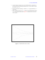
500 kHz ADC Test
Recall an s2pul parameter set. Enter nt=1 sw=100 np=8k tpwr=0 pw=0 go.
If the run terminates with an error “np not equal to number of points”
check the cable connections that were just made.
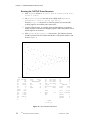
Wideband Module Test
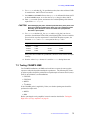
Enter sw=5e6 np=8k go. If no errors occur, enter wft and inspect the spectrum.
The noise pattern should be approximately symmetric and contain no spurious signals.
The noise level at 2.5e6 Hz should be about 1/3 that at the center.
If errors occur check the cable connections. If no errors or spurious signals occur the
installation is complete.
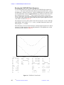
Data Transfer Test
The wideband module makes it possible to acquire data faster than the computer can
store it. A fifo underflow will then occur. VNMR 5.3 and later software warns when
this might happen and suggests a d0 or d1 value that will avoid the problem.
For a 1D acquisition with bs='n', data transfer from the Wideline NMR Module to
the Sun occurs at the end of the run. Acquisition of data with the maximum np (256k
for the beta boards) and d1=0 is possible.
For UNITYINOVA when bs>0, during arrayed or 2D operation or during real-time display
of acquisition, the data-transfer between the Wideband NMR Module and the Sun takes
place during the d1 delay period. The minimum value of d1 (required to complete the
transfer) is determined by the number of points, np, and the speed of data-transfer,
which depends on the amount of memory on the Wideline NMR Module. Incomplete
transfer causes a fifo-underflow error. The table below shows typical values of d1
versus np for the current beta boards (1 MB of memory). Released boards will have 2
36
UNITY
INOVA Solids Hardware Installation
01-999044-00 A0398
3.3 Pulse Sequences Proton Multipulse NMR
MB. They will run with faster data-transfer rates and trap for most fifo-underflow
conditions.
np
bs
d1(s)
>64k
>0, acqi, 2D, or array
operation unreliable
64k
>0, acqi, 2D, or array
0.4
32k
>0, acqi, 2D, or array
0.2
16k
>0, acqi, 2D, or array
0.1
8k
>0, acqi, 2D, or array
0.05
Operation with a shorter d1 may cause an error (fifo underflow) and halt the
acquisition. If an underflow error occurs, decrease np or increase d1. Run with
bs='n' if possible. Once a fifo underflow error has been generated it is sometimes
necessary to run one scan successfully with a small number of points (say 2k) before
continuing.
3.3 Pulse Sequences Proton Multipulse NMR
The pulse sequence source files flipflop.c, br24.c, cylbr24.c, mrev8.c, and
cylmrev8.c must be modified to function with UNITYINOVA and VNMR 5.2F.
For UNITYINOVA, the receiver is off by default (it is on for UNITYplus). When using
explicit acquisition, the receiver is turned on with the beginning of the 'acquire'
statement. For CRAMPS, this is too late—the receiver must be turned on at the
beginning of the delay 'dtau'.
Place rcvron() before the delay(dtau) or delay(dtau + tau) and before
rcvroff() after the acquire statement in each sequence.
01-999044-00 A0398
UNITY
INOVA Solids Hardware Installation
37
Chapter 3. Wideband NMR Module
38
UNITY
INOVA Solids Hardware Installation
01-999044-00 A0398
Chapter 4.
CP/MAS Solids Module Installation
The CP/MAS solids module enables Varian NMR spectrometers to run CP/MAS and
MAS experiments.
This chapter covers the installation of the CP/MAS amplifier on the NMR
spectrometer. The two sections of this chapter are the following:
• Installing the CP/MAS solids module
• Testing the CP/MAS solids module
4.1 Installing the CP/MAS Solids Module
The steps below cover installing the solids decoupler pulse amplifier and connecting
the cables. Note that 400-MHz systems do not use the Solids Control Box.
1. Enter svs(file), where file is the name of the file to save existing shim
settings.
2. Power down the system using the standard procedure.
3. Turn off the power to the console and remove the power cable from its socket.
4. Remove the rear panel and vent outlet from the top AMT linear amplifier in the
rear of the console. See Figure 11 on page 46 for the location.
5. Disconnect all cables—two coax input cables, two N-type output cables, the 25pin D-type connector, and the power cord. If coaxial attenuators are connected
to the input of the amplifier, leave them attached to the cables.
6. Remove the 4 screws from the front of the top AMT linear amplifier and slide
the amplifier out of the cabinet. Be careful because the amplifier is heavy.
7. Install the 100-W AMT amplifier in the top slot:
a.
Remove the slides and shims from the 50 W AMT amplfier(3900-12) and
attach them to the 100 W AMT (3900-15).
b.
Slide the 100 W AMT amplifier (00-993200-00) into the top slot.
c.
Secure the front panel of the amplifier to the front rails with the original
screws.
8. Reattach the cables removed in step 5 to the back of the 100 W AMT amplifier
and turn the amplifier on.
9. Remount the rear panel and vent duct in the rear of the cabinet.
10. Close the front cover, reconnect the power, and turn the system power on. Start
the data system as described in the User Guide: Solid-State NMR.
01-999044-00 A0398
UNITY
INOVA Solids Hardware Installation
39
Chapter 4. CP/MAS Solids Module Installation
11. Recall shim values by entering rts(file) su, where file is the name of the
file containing the shim values you saved in step 1.
Refer to the User Guide: Solid-State NMR for solids operating instructions and sample
preparation procedures. Refer to the manual NMR Probes Installation for information
specific to CP/MAS probes.
The fine attenuators are controlled by dpwrf or, in the XPOLAR pulse sequence by,
level1f and level2f, which range from 0 too 4095 (where 4095 is the maximum).
The parameter dpwr has a maximum value set at 49; level1 and level2 have
maximum values of 63. The observe fine attenuator is controlled by tpwrf in the range
0 to 4095. The maximum value for dpwr can be set in the config program, using the
“Attenuator” and “Upper Limit” labels.
You may have to create the parameters for fine control; for example,
create(parameter_name,'integer')
setlimit(parameter_name,4095,0,1). tpwrf can be created similarly.
4.2 Testing the CP/MAS Solids System
The CP/MAS Solids Module for Varian NMR spectrometers is used to acquire NMR
data from solid samples. The sample, usually a powder, is packed into a hollow rotor.
The rotor is placed in the probe at the “magic angle” of 54.7 from the magnetic field
and spun at a variety of speeds of up to 24 kHz. High-speed spinning at the magic
angle, coupled with high power decoupling, narrows the broad lines that are
characteristic of solid samples (typically 20 kHz) to about 1 ppm.
CAUTION:
Read this before doing any tests:
1. Run all tests with the XPOLAR pulse sequence and dm='nny' to
provide some protection to the probe from excessive decoupler duty
cycle.
2. Do not turn on the 100 W amplifier unless the output is connected to a
properly tuned probe (with a high-pass filter at J6003), to a large 50ohm load, or to a large 30-dB attenuator terminated in 50 ohms.
Refer to the manual NMR Probes Installation for tuning the decoupler and observe
channels on the probe. The probe must be installed and tuned before you can run a CP/
MAS solids experiment.
WARNING: Dangerous high rf voltages exit that can cause serious injury or death.
Avoid electric shock by completely turning off the rf and
disconnecting rf cables before removing the probe.
Testing the Amplifier
Typical power outputs are given as a guide to troubleshooting. Pulse droop should be
recorded on all systems, but accurate power measurements are only needed if the
system fails to make pulse width or γB2 specifications. Power measurements should be
made through a 30-dB, 100-W attenuator on an oscilloscope or spectrum analyzer. A
spectrum analyzer provides more accurate power measurements.
1. Check the observe amplifier (Channel B) as follows:
a.
40
UNITY
Enter rt('/vnmr/tests/hmb') to recall parameters.
INOVA Solids Hardware Installation
01-999044-00 A0398
4.2 Testing the CP/MAS Solids System
b.
Enter xpol='y' p2=1e4 at=0.01 d1=.05 nt=1e6 level1=63
level1f=4095 to set up for rapid pulsing.
c.
Attach the observe cable from the magnet leg to a large 30-dB attenuator.
Attach the output of the attenuator to a oscilloscope or spectrum analyzer.
d. Set the decoupler to OFF by entering dm='nnn' tpwr=63
tpwrf=4095 go; then measure the power and droop of observe pulse
amplifier. It should meet the following values:
• Minimum power: 300 W, 220 Vpp, +54 dBm (6.3 Vpp, when
measured through a 30-dB attenuator).
• Maximum droop: 2% over 10 ms.
e.
Enter aa to stop the acquisition and then reattach the observe cable to the
probe.
2. Check the AMT decoupler amplifier (channel A) according to the following
steps. The maximum drive to the AMT should not exceed +2 dBm.
a.
Disconnect the input to Channel A of the AMT amplifier from the ATTN/
SW board and then connect OUT 1 to a power meter.
b.
Set level2=63 level2f=4095 nt=1e6 dm='nny' sw=1e5
np=128 d1=0.1
c.
Enter go and add sufficient in-line attenuation at the input of the AMT
amplifier so that the peak power does not exceed 2 mW (+3 dBm).
d. Enter aa to stop the acquisition, dm='n' su to reset the power, and then
reconnect the AMT amplifier.
Adjusting Decoupler Field Strength
1. Fill a rotor with dioxane (00-957734-01) and cap it with a Torlon end cap
(brown). Note that any other type of end cap will dissolve in the dioxane.
WARNING: The 1,4-dioxane sample (00-957734-01) is a cancer suspect agent
containing flammable liquid oxidizers. See the enclosed MSDS for
additional information and handling precautions.
2. Spin the sample slowly (200–300 Hz).
3. Enter rtp('/vnmr/tests/hmb') seqlib='xpolar'. Use XPOLAR
with xpol='n'.
CAUTION:
High spinning speeds can cause the rotor to shatter, creating a
potential physical hazard to the operator. Never spin 7-mm PSZ
(zirconia) rotors (white or off-white in color) above 7.2 kHz or silicon
nitride rotors (gray) above 9.5 kHz.
Decoupler power greater than 2 W will damage a switchable probe.
The maximum value for dpwr on a 200, 300, or 400 MHz system with a
linear amplifier on the decoupler channel has been set to 49, which
corresponds to approximately 2 W of power. For this reason, do not
use or alter dpwr for solids operation. Use the XPOLAR pulse
sequence rather than S2PUL.
01-999044-00 A0398
UNITY
INOVA Solids Hardware Installation
41
Chapter 4. CP/MAS Solids Module Installation
Follow all pulse duration, pulse power and duty cycle warnings if given
for a particular probe. Generally, pulse durations can be increased
with a proportional decrease in pulse power.
4. Tune the probe according to the instructions in the manual NMR Probes
Installation. Tune the decoupler channel before the observe channel and with a
high-pass filter in place for a return ratio of 50 dB or better.
5. Check that dm=nny, level2=63, and level2f=4095.
6. Record a pair of 13C spectra by entering dof=50000, –50000 ga (see Figure
10).
ACQUISITION
sfrq 100.57
tn
C13
at
0.100
np
6016
sw
3000.0
xpol
n
tpwr
55
tpwrf
51
pw
8.0
p1
0
d1
10.000
tof
0
nt
1
ct
1
SAMPLE
date
April 1
file
exp
DECOUPLING
dn
H1
dof
arrayed
dm
nny
dmm
c
dpwr
63
level1
57
level1f
200
level2
63
level2f
4095
PROCESSING
lb
10.00
sb
not used
gf
not used
awc
not used
lsfid not used
phfid not used
wtfile
proc
ft
fn
32768
FLAGS
il
n
toss
n
pdp
n
dp
y
SPECIAL
srate
415
temp not used
werr
wexp
wbs
wnt
FLAGS
ai no ph
Gamma-H2 calculation
See J. Magnetic Resonance 7:442 (1972)
jo = 284.00 Hz,
dof[1] = –50000.00 Hz,
dof[2] = 50000.00 Hz
jr[1] = 165.00 Hz,
jr[2] = 167.00 Hz
Gamma-H2
=
69404.97 Hz
90 degree pulse =
3.6 usec
coalescence frequency =
–457.51 Hz
Figure 10. Decoupler Field γB2
42
UNITY
INOVA Solids Hardware Installation
01-999044-00 A0398
4.2 Testing the CP/MAS Solids System
7. Measure the residual splitting of the dioxane triplet. Use h2cal to calculate
γB2. Minimum values are shown in Table 1.
Table 1. Maximum γB2 Values
Magnet
Varian RT Probe,
7mm
Varian VT Probe,
7mm
Doty Probe, 7mm
HS
200 MHz
75 kHz
—
60 kHz
300 MHz
75 kHz
80 kHz
60 kHz
400 MHz
60 kHz
70 kHz
55 kHz
Other Probes
See individual
specs
Set level2 to achieve a γB2 as close to these minimum values as possible. Do
not exceed this power level for any other experiment. Note this value.
8. If the probe does not make specification, check for rf losses in the decoupler
circuitry going to the probe.
01-999044-00 A0398
UNITY
INOVA Solids Hardware Installation
43
Chapter 4. CP/MAS Solids Module Installation
44
UNITY
INOVA Solids Hardware Installation
01-999044-00 A0398
Chapter 5.
Solids Cabinet Preparation and
Installation
This chapter describes preparation and installation procedures for the solids cabinet
and installation procedures for the Solids Relay Driver board.
5.1 Preparing to Install the Solids Cabinet
Before starting to install the solids cabinet, make sure you have the correct power
supply, tools, and sufficient space for the installation. Refer to Table 2 for weights and
dimensions and to the UNITYINOVA Installation Planning Guide for additional planning
details, such as air conditioning requirements.
1. The solids cabinet contains Class A/AB rf amplifiers requiring a high-current
power source. Verify that the main power supply is 240 Vac single-phase, 30 A
dedicated line, separate from the 20 A power line used by the UNITYINOVA
console. Figure 11 illustrates the solids cabinet with the front panel removed.
2. The following tools and equipment are needed to perform the upgrade and
performance testing. Collect these before starting.
• Dual-trace oscilloscope capable of accurate voltage measurements from dc
to 400 MHz
• 500 W, 30 dB attenuator
• 2 W rotary attenuator, 0 to 100 dB in 10 dB and 1 dB steps
• Spectrum analyzer
• Complete Varian field service engineer tool kit
3. Check the items in the shipping kit against the parts list. If all the parts on the list
are included in the kit, proceed to the next step. If anything is missing, obtain it
before proceeding.
Table 2. Dimensions of Complete Solids Cabinet and UNITYINOVA Cabinet
Component
Height
Width
Depth
Weight
Complete Solids
Cabinet
142.3 cm
56 in.
55.3 cm
21.8 in.
78 cm
30.7 in.
< 272 kg
< 600 lb
UNITYINOVA
Standard Cabinet
124.5 cm
49 in.
110.7 cm
43.6 in.
78 cm
30.7 in.
~ 272 kg
~ 600 lb
01-999044-00 A0398
UNITY
INOVA Solids Hardware Installation
45
Chapter 5. Solids Cabinet Preparation and Installation
WARNING: Remember that during the installation the magnet is up to field.
Equipment and tools used by the moving crew must be evaluated for
safety. Install a plastic chain (or chain of other nonmagnetic material)
at about 42 in. (107 cm) from the magnet body. This will serve as a
reminder to prevent magnetic materials (e.g. , consoles) from being
pulled into the magnet body.
4. Verify that there is enough room to accommodate the solids cabinet on the floor
plan of the laboratory by following the guidelines below:
a.
Measure the distance between the edge of the UNITYINOVA console and the
centerline of the magnet.
If this distance is greater than the distance indicated in Table 3 for the
specific system, go on to step 5:
b.
If the distance is less than the distance indicated above, determine how
much distance must be added to accommodate the solids cabinet:
=
–
distance from above
table
actual distance
additional distance
needed
Status panel
Sorensen VT
controller (optional)
Low band 1 kW
amplifier
Low band
power supply
High band 1 kW
amplifier
High band EHT
power supply
Figure 11. Solids Cabinet Open Front View
46
UNITY
INOVA Solids Hardware Installation
01-999044-00 A0398
5.2 Installing the Solids Relay Driver Board
Table 3. Minimum Distances of UNITYINOVA Console from Magnet Centerline
c.
System (MHz)
Distance
300/51
170 cm (67 in.)
300/89
185 cm (73 in.)
400/54
185 cm (73 in.)
400/89
185 cm (73 in.)
Place the acquisition console at the correct distance. Disconnect all cables
from the magnet leg and move the cables away from the right side of the
console.
5. Shut down the data system using the steps below:
a.
CAUTION:
Exit VNMR by entering svs(file), where file is the name of the
shim file. Then enter exit.
Shut down the system according to the instructions provided in the
manual User Guide: Solid-State NMR. Failure to shut down the system
properly can corrupt system files.
b.
Shut down VNMR and UNIX system according to instructions in the
User Guide: Solid-State NMR..
c.
After VNMR and UNIX are shut down, turn off the power switch located
at the rear, center of the acquisition console.
d. Remove the power connector from the rear of the acquisition console.
6. For convenience, remove the back panel of the acquisition console, which covers
the Relay Driver board as shown in Figure 12 on page 48. Set the back panel
aside until the modification is complete.
7. Carefully push the solids cabinet up towards the right side of the UNITYINOVA
console (looking from the front) so that there is 6 in. (15 cm) between them and
both front panels face the same directions. The minimum distance between the
edge of the solids cabinet and the magnet must be at least 42 in. (107 cm) for 300
MHz magnets and 48 in. (122 cm) for a 400 MHz or any widebore (89 mm)
magnet.
5.2 Installing the Solids Relay Driver Board
This section describes replacing the Relay Driver board (00-992962-00) with the
Solids Relay Driver board (00-992962-01). The solids cabinet is connected to the
UNITYINOVA console through the Solids Relay Driver board, which is located in the rear
of the UNITYINOVA console, behind the rf control card cage. The illustrations in Figure
12 shows the location of the Relay Driver board as well as the front and rear layouts of
the two UNITYINOVA console cabinets.
Before you begin, shut down VNMR and power down the system as described in the
manual User Guide: Solid-State NMR.
01-999044-00 A0398
UNITY
INOVA Solids Hardware Installation
47
Chapter 5. Solids Cabinet Preparation and Installation
Front View
PFG amplifier
RF card cage
320
RF control
card cage
620
PTS frequency
synthesizers
620
Digital
card cage
Linear amplifiers
Shim power
supply
Power supply
Back View
Fan
panel
Fan
panel
Cable tray
Solids Relay Driver
board (00-992962-01)
Breakout
panel
J8212
R
S
J8216
SPARE 1
2
3
2
A
P
B
U
S
AMT amplifier
vent outlets
J8233
U
S
E
R
J8215
RCVR GATE
J8211
+5V
ATTEN
EMERG
J232 ACK —
J232 STB —
J233 ACK —
J233 STB —
J8201
R
E
M
O
T
E
J8217
SPARE 2
S
T
A
T
U
S
J8219
SPARE 4
CLKSTB
ACK
A
P
J8218
SPARE 3
U
S
E
R
A
P
J8210
SPARE 5
J8213
VT controller
Shim power
supply
Power supply
Figure 12.
48
UNITY
UNITY
INOVA Spectrometer, Front and Back Views
INOVA Solids Hardware Installation
01-999044-00 A0398
5.3 Installing the Solids Cabinet
1. If not already done, remove the appropriate panel at the rear of the UNITYINOVA
console to gain access to the Relay Driver board, see Figure 12.
2. Disconnect the ribbon cable at J7001. Disconnect the power cable at J7004.
Disconnect the tune relay cable at J7301
3. Remove the Relay Driver board (00-992962-00) by removing the four screws
that hold the board in place.
4. Install the Solids Relay Driver board (00-992962-01) by inserting the four
screws removed step 3.
5. Connect the ribbon cable at J7001 and connect the power cable at J7004.
Reconnect the tune relay cable at J7301.
6. Connect one end of the second power cable (00-993140-00) to J7003 on the
Solids Relay Driver board. Connect the other end to the +5 V rail (upper, labeled
TBxx) and GND rail (lower, labeled TB2x) on the control card cage.
5.3 Installing the Solids Cabinet
The following steps describe how to install the solids cabinet. Figure 13 illustrates the
open back of the solids cabinet and the relay panel. The table shows which steps to
follow for each solids module.
When Installing
Do These Steps
Wideline
1 through 5
CRAMPS/Multipulse
5 through 10
Complete solids
1 through 10
1. Locate the cable connected between J4072 (liquids AMT channel B out) and
K5004-2 (preamplifier housing). Remove this cable.
2. Locate the cable (00-990626-16) connected to K7200-C in the solids cabinet.
Connect the other end to J4072 (liquids AMT channel B out).
3. Locate the cable (00-990626-17) connected to K7202-C in the solids cabinet
Connect the other end to K5004-2 in the preamplifier housing.
4. Connect J7022 on the Solids Relay Driver board to J26 on the AMT 1 kW
amplifier (RF Blanking, 00-958297-16).
5. Connect harness (00-990729-00) between the UNITYINOVA console and the solids
cabinet as follows:
Standard cabinet:Solids Relay Driver board: J7009, J7011, J7030
Solids Status board: J7101, J7103, J7104, J7106, J7107,
J7108, J7109, J7110
Solids cabinet: Solid relay panel: J7206
1 kW high-band amplifier: J7703
6. Connect J7023 on the Solids Relay Driver board to J7714 on the 1 kW Hi band
amplifier (RF Blanking, 00-958298-16).
7. Locate the cable connected between J4073 (liquids AMT channel A out) and
K5004-3 (preamplifier housing). Remove this cable.
01-999044-00 A0398
UNITY
INOVA Solids Hardware Installation
49
Chapter 5. Solids Cabinet Preparation and Installation
8. Locate the cable (00-990626-16) connected to K7201-C in the solids cabinet.
Connect the other end to J4073 (liquids AMT channel A out).
9. Locate the cable (00-990626-17) connected to K7203-C in the solids cabinet.
Connect the other end to K5004-3 in the preamplifier housing.
10. Connect the solids cabinet to the mains (208, 220, or 240 Vac 30A). Do not
switch the instrument on at this time. Wait until the hardware installation is
completed.
5.4 Setting the AMT Amplifier Main Supply
The facility voltage entering the amplifier can be set to 230 or 208 Vac. Selection is
made by connecting a jumper on the M3000 module at the appropriate taps. This is
illustrated in Figure 14.
Inside of relay panel
Fan panel
K7200
K7201
Open relay panel
K7205
K7202
Sorensen VT
controller
Low band 1 kW
amplifier
Low band
power supply
High band 1kW
amplifier
High band EHT
power supply
Figure 13. Solids Cabinet, Open Back View and the Relay Panel
50
UNITY
INOVA Solids Hardware Installation
01-999044-00 A0398
5.4 Setting the AMT Amplifier Main Supply
230
Jumper placement
208
Ground
AC
Figure 14. AC Input at Rear of AMT M3000 Amplifier
01-999044-00 A0398
UNITY
INOVA Solids Hardware Installation
51
Chapter 5. Solids Cabinet Preparation and Installation
52
UNITY
INOVA Solids Hardware Installation
01-999044-00 A0398
Chapter 6.
Wideline Module Tests
This chapter contains test procedures for the wideline module. The tests are broken into
two groups as follows:
RF transmitter performance tests:
• Liquids observe transmitter rf signal path
• Solids observe transmitter rf signal path
• Decoupler transmitter performance
• Solids cabinet status light and safety switch performance
NMR tests:
• Wideline solids test sample kit
• Deuterium 90 pulse and system sensitivity measurement
• Sodium 90 pulse and sensitivity measurement
• System recovery time
• Wideline spectral appearance
• Liquids performance
CAUTION:
•
•
•
•
•
Read the following cautions:
Make sure that all amplifiers are terminated in appropriate 50-ohm
loads at all times.
The high power available from the amplifier in the solids cabinet is
intended only for solids experiments. Applying this power to a liquids
probe will destroy the probe. Before turning on the amplifier in the
solids cabinet, check that the appropriate solids probe has been put in
place.
Always disable all high-power solids amplifiers before installing any
probe.
Confirm that the rf signal being measured can never exceed the
maximum input signal of the measuring device.
Do not block any of the ventilation holes in the solids cabinet. Even on
standby, the amplifiers radiate considerable heat.
01-999044-00 A0398
UNITY
INOVA Solids Hardware Installation
53
Chapter 6. Wideline Module Tests
6.1 Testing RF Transmitter Performance
This series of tests evaluates the solids cabinet relay and attenuator operation as well
as the 1 kW amplifier power output and performance.
Liquids Observe Transmitter RF Signal Path
1. Recall the parameters: rtp('/vnmr/stdpar/H2').
2. Enter the following parameters to observe the transmitter pulse along the
transmitter pathway: nt=1e5 pw=100 dm='n' rof1=30 rof2=0.2
alfa=0 sw=1e5 at=0.001 tpwr=63.
3. On the solids cabinet control panel (see Figure 15), set the LO BAND switch to
HI POWER. Enter go.
4. Confirm that the transmitted signal level at J25 rf input on the AMT M3201 is
54 dBm or less.
5. Halt the acquisition with aa and replace the cables.
Testing the Solids Observe Transmitter RF Signal Path
1. The broadband amplifier requires no tuning but must be properly terminated by
a 50-ohm load at all times. To verify its operation, switch the LO BAND to
HI POWER and observe the rf using a 500-W, 30-dB attenuator and additional
attenuation as required. Check the output at the magnet observe port as described
in steps 5 and 6 below.
2. Confirm that the blanking gate cable is connected as described below for the
appropriate amplifier and required gate logic.
HI BAND
LO BAND
LO
POWER
LO
POWER
STATUS
HI POWER ENABLE
OFF
AC
POWER
HI BAND
CW
CW
PULSE
PULSE
CAUTION
SHUT OFF
HI
POWER
PLATE
CURRENT
HI
POWER
–
+
GRID
CURRENT
TEMP
–
TEMP
DUTYCYC
DUTYCYC
P WIDTH
P WIDTH
OVER DR
OVER DR
+
Figure 15. High-Power Amplifier Control Panel on Solids Cabinet
54
UNITY
INOVA Solids Hardware Installation
ON
LO BAND
01-999044-00 A0398
6.1 Testing RF Transmitter Performance
3. Turn on the AMT amplifier at the front panel and check that all interlocks go out.
Only the light labeled POWER should be lit. If the status lights labeled PULSE
WIDTH and/or DUTY CYCLE are lit, move jumper J2 on the Solids Relay Driver
board to short the middle and bottom pins.
4. Confirm that the minimum full power output in the pulsed mode is 1 kW (60
dBm). This should not require adjustment of the amplifier gain.
5. Observe the pulse shape using a 8-ms pulse width. Do not confuse the rf pulse
rise and fall times with the amplifier turn-on time of 15 sand turn-off time of 3
s. The pulse droop for an 8-ms rf pulse would be 3% or less.
6. Confirm the absence of any amplifier gating/blanking transient pulses coincident
with the external amplifier gating signal.
Decoupler Transmitter Performance
Confirm that the decoupler transmitter output to the probe normal as for liquids high
band when the amplifier switch is in the LO POWER position. The decoupler should
perform as in a normal, liquids-only NMR spectrometer and should be under the
control of dpwr as usual.
Some parameters in the acquisition group may not be displayed in dg if they are set to
zero. Be aware of power parameters like tpwr, dpwr, and pulse lengths. Check their
values at experiment setup!
Solids Cabinet Status Light and Safety Switch Performance
1. Make sure that there is no observe or decoupler output to the probe with the
amplifier output switch in the OFF position.
2. Make sure that rf output is restored when the ON switch is toggled. The status
light goes off when the amplifier output switch is on.
01-999044-00 A0398
UNITY
INOVA Solids Hardware Installation
55
Chapter 6. Wideline Module Tests
6.2 Wideline NMR Tests
This section procedures for testing the wideline module.
Wideline Solids Test Sample Kit
The wideline solids test sample kit (00-949065-23) consists of the following samples:
Part No.
Description
969104-00
100% malonic acid-d4
969104-01
100% NaNO3
969104-03
1 M NaCl, 2% D2O, 98% H2O
Verify the following NMR performance using the 1 M NaCl, 2% D2O, 98% H2O
standard sample (Part No. 00-969104-03).
Measuring 90 Pulse and System Sensitivity
1. Enter rtp('/vnmr/stdpar/H2') to recall parameters.
2. Set up the spectrometer for data acquisition as follows: nt=1 dm='n'
dp='y' lb=50 gain=0 rof1=30 alfa=0 sw=1e5 np=max fn=65536
3. Enter su.
4. Tune the probe to the deuterium resonance frequency (refer to the NMR Probes
Installation manual).
5. Determine the 90 pulse for2H. Enter this value for pw90.
6. Enter sw=1e6. Set the transmitter offset tof such that the deuterium signal
resonates 250 kHz from the transmitter frequency. Acquire one transient by
entering ga. Display the resultant spectrum in the absolute value mode, with
vs=1000, normalized, nm. Confirm that the quadrature image is less than 1%
by height as compared to the main resonance.
7. Set sw=1e5.
Set tof such that the deuterium signal resonates 25 kHz from the transmitter
frequency. Acquire one transient by typing ga. Display the resultant spectra in
the absolute value mode, with vs=1000, normalized, nm. Confirm that the
quadrature image is less than 1% by height as compared to the main resonance.
8. Set tof to 1 kHz off-resonance.
9. Measure 2H sensitivity. Use a spectral noise region of 20 kHz, centered
approximately 10 kHz off-resonance. Refer to Figure 16 for sample spectrum
and to Table 4 for specifications.
56
UNITY
INOVA Solids Hardware Installation
01-999044-00 A0398
6.2 Wideline NMR Tests
S/N 249.6
800
1000 kHz
ACQUISITION
sfrq 61.395
tn
H2
at
0.008
np
16384
sw
1e+06
fb
1e6
bs not used
ss
0
tpwr
57
pw
2.2
p1
0
d1
4.000
d2
0
tof
0
nt
1
ct
0
700
600
SAMPLE
date
Apr 1
solvent
none
file
/vnmr/~
stdpar/H2
DECOUPLING
dn
H1
dof
0
dm
n
dmm
c
dmf
4000
homo
n
500
400
300
PROCESSING
lb
50.00
sb
not used
gf
not used
awc
not used
lsfid not used
phfid
90.0
wtfile
proc
ft
fn
65536
math
f
200
100
0
FLAGS
il
in
dp
hs
n
n
y
nn
SPECIAL
temp not used
werr
wexp
wbs
wnt
Figure 16. Sample Spectrum, S/N = 249.6, 300-MHz System
Table 4. 90 Pulse and Signal-to-Noise Specifications
System
Nucleus
PW90
Frequency
S/N
400 MHz
2H
≤ 3.0 s
61.4
300:1
23Na
≤ 3.0 s
105.8
630:1
2H
≤ 2.5 s
46.1
200:1
23Na
≤ 2.5 s
79.4
475:1
2H
≤ 2.2 s
30.7
110:1
23Na
≤ 2.2 s
52.9
315:1
300 MHz
200 MHz
01-999044-00 A0398
UNITY
INOVA Solids Hardware Installation
57
Chapter 6. Wideline Module Tests
Sodium 90 Pulse and Sensitivity Measurement
Use the standard liquid sample(00-969104-03), the same as for 2H.
1. Enter rtp('/vnmr/tests/Na23wl') to recall parameters.
1. Set up the spectrometer for data acquisition as follows: seqfil='s2pul'
nt=1 sw=1e5 np=max dm='n' dp='y' lb=50 gain=0 rof1=30
alfa=0 fn=65536.
2. Tune the probe to the sodium resonance frequency (refer to the NMR Probes
Installation Manual).
3. Determine the 90 pulse for23Na. Enter this value for pw90.
4. Set tof to 1 kHz off-resonance.
5. Measure 23Na sensitivity. Use a spectral noise region of 20 kHz, centered
approximately 10 kHz off-resonance. Refer to Figure 17 for sample spectrum.
1000 kHz
ACQUISITION
sfrq 105.800
tn
Na23
at
0.004
np
16384
sw
2e+06
fb
1e+06
bs not used
ss
0
tpwr
57
pw
2.2
p1
0
d1
4.000
d2
0
tof
0
nt
1
ct
0
500
SAMPLE
date
Apr 1
solvent
none
file
/vnmr/~
tests/Na23wl
DECOUPLING
dn
H1
dof
0
dm
n
dmm
c
dmf
4000
homo
n
PROCESSING
lb
50.00
sb
not used
gf
not used
awc
not used
lsfid not used
phfid
90.0
wtfile
proc
ft
fn
65536
math
f
0
FLAGS
il
in
dp
hs
n
n
y
nn
SPECIAL
temp not used
werr
wexp
wbs
wnt
Figure 17. Sample Sodium 90 Pulse and Sensitivity Spectrum, 300-MHz System
58
UNITY
INOVA Solids Hardware Installation
01-999044-00 A0398
6.2 Wideline NMR Tests
System Recovery Time
This test is run with no sample in the probe.
1. Remove the sample and retune the probe.
2. Set the spectrometer as follows: rof2=0 sw=2e6 np=16384 nt=1
alfa=0.
3. Set pw to the value of pw90.
4. Enter go.
Display the resulting FID. Set the cursors such that the left-hand cursor is at the
very beginning of the FID and the right-hand cursor is at the point in the FID
where the normal noise level returns. The difference between the cursors should
be less than 12 s. Refer toFigure 18 for a sample FID display.
System recovery time = 7.1
ACQUISITION
sfrq 105.800
tn
Na23
at
0.004
np
16384
sw
2e+06
fb
1e+06
bs not used
ss
0
tpwr
57
pw
2.2
p1
0
d1
4.000
d2
0
tof
0
nt
1
ct
0
SAMPLE
date
Apr 1
solvent
none
file
/vnmr/~
tests/Na23wl
DECOUPLING
dn
H1
dof
0
dm
n
dmm
c
dmf
4000
homo
n
PROCESSING
lb
50.00
sb
not used
gf
not used
awc
not used
lsfid not used
phfid
90.0
wtfile
proc
ft
fn
65536
math
f
FLAGS
il
in
dp
hs
n
n
y
nn
SPECIAL
temp not used
werr
wexp
wbs
wnt
Figure 18. System Recovery Time, Sample FID Display
01-999044-00 A0398
UNITY
INOVA Solids Hardware Installation
59
Chapter 6. Wideline Module Tests
Wideline Spectral Appearance
1. Insert wideline solids sample (Part No. 00-969104-00). Tune the probe carefully
for the 2H frequency. If you need to, refer to the NMR Probes Installation
manual for tuning instructions.
2. Acquire a quadrupolar signal of the malonic acid-d4 sample using the SSECHO
pulse sequence and following the instructions in the User Guide: Solid-State
NMR. Be sure to center the sample in the coil.
3. Enter rtp('/vnmr/tests/H2wl') to recall parameters.
4. Set the following parameters: nt=16 d1=10 rof1=10 rof2=5 alfa=0.0
tau1=20 tau2=15 seqfil='ssecho' np=16384 lb=1000.
The quality of the spectrum is very sensitive to acquisition and processing
parameters. Be sure that spectrum is processed in the phased (ph) mode, not the
absolute value (av) mode. If all previous tests have been successful, any spectral
imperfection is most likely due to these parameter settings and not hardware
malfunctions. When phased properly, the height of the two horns of the pattern
should differ by less than 5%.
The sample has D2O; therefore, you get a center spike that will phase correctly
only if np=16384.
5. Set pw to the 90 pulse for2H.
Figure 19 shows an example SSECHO FID using lsfid and correct phase.
Refer to Figure 20 for all other spectral parameters. Set tof on-resonance for
the wideline sample.
6. Acquire 16 transients of data.
7. Look for the following spectral characteristics:
a.
The amplitude of the two “horns” (perpendicular singularities) should be
within 5% of each other. If the horns are not within the specification, the
tof is not truly on resonance. To set the tof on-resonance, set the two
cursors on the horns of the wideline spectrum and enter split.
One cursor will be set at the middle of the broad peak. Enter movetof to
set the transmitter offset to this middle position of the broad resonance.
b.
The “shoulders” to the very outside of the broad resonance should be
clearly visible and well-defined.
c.
The broad resonance should be very symmetrical in appearance.
Figure 19. SSECHO FID for Malonic Acid-d6 Using lsfid
60
UNITY
INOVA Solids Hardware Installation
01-999044-00 A0398
6.2 Wideline NMR Tests
8. Set compul='y'.
Repeat steps 1 to 5 above. Although the echo maximum may change position,
symmetry of the horns should be the same. The edges of the spectrum will alter
and become sharper. This flag (i.e., compul) changes the π/2 pulses from single
to composite and so checks the 90 phase shifting speed of the spectrometer.
Refer to Figure 20 and Figure 21.
9. Repeat steps 1 to 4 above for sample 00-969104-01, the sodium solid standard
sample; tune the probe to the sodium frequency. Recall the standard test
parameter by entering rt('/vnmr/tests/Na23wl'). The sodium solid
standard FID appears similar to the example in Figure 22.
Refer to Figure 23 for the spectral appearance and spectral parameters. Again,
the criteria in step 5 should be observed.
Apply the symmetry test to the two horns. You should be able to see edges at 200
kHz. (Notice to the left of the pattern is another peak due to aluminium
background that may not phase correctly. Ignore it.)
1600 kHz
ACQUISITION
sfrq 61.395
tn
H2
at
0.082
np
16384
sw
2e+06
fb
1e+06
tof
0
tpwr
57
pw
2.2
p1
0
p180
0
d1
10.000
tau1
20.0
tau2
15.0
1200
1000
SAMPLE
date
Apr 1
solvent
none
file
/vnmr/~
tests/H2wl
DECOUPLING
dn
H1
dof
0
dm
n
dmm
c
dmf
4000
homo
n
TRANSIENTS
bs
not used
ss
0
nt
16
ct
0
800
600
PROCESSING
lb
1000.00
sb
not used
gf
not used
awc
not used
lsfid
10
phfid
90.0
wtfile
proc
ft
fn
65536
400
200
FLAGS
il
in
dp
hs
compul
0
n
n
y
nn
n
SPECIAL
temp not used
werr
wexp
wbs
wnt
Figure 20. Wideline SSpectrum of Malonic Acid-d6 With compul='n'
01-999044-00 A0398
UNITY
INOVA Solids Hardware Installation
61
Chapter 6. Wideline Module Tests
10. Verify that there is no acoustical ringing at the deuterium frequency using tau1
and tau2 values of 20 s.Test the probe with no sample present. Tune the probe
to the deuterium frequency and acquire 16 transients. The spectrum should have
a flat noise baseline with no broad peaks. Refer to Figure 24 for test parameters
and results with a probe that does exhibit acoustical ringing.
1600 kHz
1200
ACQUISITION
sfrq 61.395
tn
H2
at
0.082
np
16384
sw
2e+06
fb
1e+06
tof
0
tpwr
57
pw
2.2
p1
0
p180
0
d1
10.000
tau1
20.0
tau2
15.0
1000
800
600
SAMPLE
date
Apr 1
solvent
none
file
/vnmr/~
tests/H2wl
DECOUPLING
dn
H1
dof
0
dm
n
PROCESSING
lb
1000.00
sb
not used
gf
not used
awc
not used
lsfid
10
phfid
90.0
wtfile
proc
ft
fn
65536
TRANSIENTS
bs
not used
ss
0
nt
16
ct
0
werr
wexp
wbs
wnt
400
200
FLAGS
il
in
dp
hs
compul
0
n
n
y
nn
y
SPECIAL
temp not used
Figure 21. Wideline Spectrum With compul='y'
Figure 22. 23Na FID of Sodium Standard (NaNO3) Starting at Top of Echo
62
UNITY
INOVA Solids Hardware Installation
01-999044-00 A0398
6.2 Wideline NMR Tests
11. The wideline probe does exhibit 23Na and 27Al background due to the glass rods
in the coil support. Refer to Figure 25 and Figure 26 for an example of the
expected sodium and aluminum background.
1600 kHz
1200
ACQUISITION
sfrq 105.800
tn
Na23
at
0.082
np
16384
sw
2e+06
fb
1e+06
tof
0
tpwr
57
pw
2.7
p1
0
p180
0
d1
1.000
tau1
20.0
tau2
15.0
1000
800
600
SAMPLE
date
Apr 1
solvent
none
file
/vnmr/~
tests/Na23wl
DECOUPLING
dn
H1
dof
0
dm
n
PROCESSING
lb
1000.00
sb
not used
gf
not used
awc
not used
lsfid
10
phfid
90.0
wtfile
proc
ft
fn
65536
TRANSIENTS
bs
not used
ss
0
nt
16
ct
0
werr
wexp
wbs
wnt
400
200
FLAGS
il
in
dp
hs
compul
0
n
n
y
nn
n
SPECIAL
temp not used
Figure 23. Wideline Spectrum With Sodium Solid Standard
01-999044-00 A0398
UNITY
INOVA Solids Hardware Installation
63
Chapter 6. Wideline Module Tests
1600 kHz
1200
ACQUISITION
sfrq 61.395
tn
H2
at
0.082
np
16384
sw
2e+06
fb
1e+06
tof
0
tpwr
57
pw
2.2
p1
0
p180
0
d1
1.000
tau1
20.0
tau2
15.0
1000
800
600
SAMPLE
date
Apr 1
solvent
none
file
/vnmr/~
tests/H2wl
DECOUPLING
dn
H1
dof
0
dm
n
PROCESSING
lb
1000.00
sb
not used
gf
not used
awc
not used
lsfid
10
phfid
90.0
wtfile
proc
ft
fn
65536
TRANSIENTS
bs
not used
ss
0
nt
16
ct
0
werr
wexp
wbs
wnt
400
200
FLAGS
il
in
dp
hs
compul
0
n
n
y
nn
n
SPECIAL
temp not used
Figure 24. Sample Spectrum From a Probe With Acoustical Ringing
2000 kHz
1600
ACQUISITION
sfrq 105.800
tn
Na23
at
0.082
np
16384
sw
2e+06
fb
1e+06
tof
0
tpwr
57
pw
2.7
p1
0
p180
0
d1
1.000
tau1
20.0
tau2
15.0
1400
1200
1000
800
600
SAMPLE
date
Apr 1
solvent
none
file
/vnmr/~
tests/Na23wl
DECOUPLING
dn
H1
dof
0
dm
n
PROCESSING
lb
1000.00
sb
not used
gf
not used
awc
not used
lsfid
10
phfid
90.0
wtfile
proc
ft
fn
65536
TRANSIENTS
bs
not used
ss
0
nt
100
ct
0
werr
wexp
wbs
wnt
400
200
FLAGS
il
in
dp
hs
compul
0
n
n
y
nn
n
SPECIAL
temp not used
Figure 25. Sample Spectrum With Sodium Background
64
UNITY
INOVA Solids Hardware Installation
01-999044-00 A0398
6.2 Wideline NMR Tests
2000 kHz
1600
ACQUISITION
sfrq 105.800
tn
Na23
at
0.082
np
16384
sw
2e+06
fb
1e+06
tof
0
tpwr
57
pw
2.7
p1
0
p180
0
d1
1.000
tau1
20.0
tau2
15.0
1400
1200
1000
800
600
SAMPLE
date
Apr 1
solvent
none
file
/vnmr/~
tests/Na23wl
DECOUPLING
dn
H1
dof
0
dm
n
PROCESSING
lb
1000.00
sb
not used
gf
not used
awc
not used
lsfid
10
phfid
90.0
wtfile
proc
ft
fn
65536
TRANSIENTS
bs
not used
ss
0
nt
100
ct
0
werr
wexp
wbs
wnt
400
200
FLAGS
il
in
dp
hs
compul
0
n
n
y
nn
n
SPECIAL
temp not used
Figure 26. Sample Spectrum With Sodium And Aluminium Background
01-999044-00 A0398
UNITY
INOVA Solids Hardware Installation
65
Chapter 6. Wideline Module Tests
66
UNITY
INOVA Solids Hardware Installation
01-999044-00 A0398
Chapter 7.
CRAMPS/Multipulse Module Tests
The CRAMPS/Multipulse Solids Module enables Varian UNITYINOVA spectrometers to
run CRAMPS and multipulse experiments. The CRAMPS/multipulse experiment is
normally used to observe 1H. In CP/MAS, the 1H amplifier is used as a heteronuclear
decoupler, while in CRAMPS the 1H amplifier is used as an high-power observe
channel. This chapter contains system tests to check the performance of the CRAMPS/
Multipulse module. The following is a list of the tests that are described:
RF transmitter performance tests
• 1 kW amplifier tuning
• Liquids observe transmitter rf signal path
• Solids observe transmitter rf signal path
• Third cabinet status light and safety switch performance
• AMT amplifier calibration
• 1 kW amplifier calibration gating
CRAMPS/Multipulse NMR tests
• Decoupler calibration
• FLIPFLIP
• FLIPFLOP
• MREV8
• 1H wideline
CRAMPS probe test (Varian-supplied probe only)
• MREV8 narrowing at magic angle
• BR24 narrowing at the magic angle
CAUTION:
•
•
•
•
•
Read the following cautions:
Make sure that all amplifiers are terminated in appropriate 50-ohm
loads at all times.
The high power available from the amplifier in the third cabinet is
intended only for solid state. Applying this power to a liquids probe
will destroy the probe. Before turning on the amplifier in the third
cabinet, check that the appropriate solids probe has been put in place.
Disable all high-power solids amplifiers before installing any probe.
Confirm that the rf signal being measured can never exceed the
maximum input signal of the measuring device.
Do not block any of the ventilation holes in the third cabinet. Even on
standby, the amplifiers radiate considerable heat.
01-999044-00 A0398
UNITY
INOVA Solids Hardware Installation
67
Chapter 7. CRAMPS/Multipulse Module Tests
7.1 Tuning the High-Power (Cavity) Amplifier
The most reliable method for tuning the cavity amplifier (shown in Figure 27) requires
a Bird through-line wattmeter on the input to the cavity and some other power
measuring device on the output from the cavity. The output power can be measured
using a 30-dB, 500-W attenuator with an additional 30-dB, 5-W attenuator coupled to
a Bird meter or spectrum analyzer, or, if necessary, by performing NMR pulse width
calibrations. Grid current should be monitored at the status panel using an oscilloscope.
The cavity amplifier has five adjustments that must be optimized for best performance.
While making these adjustments, the grid current can rise dangerously if the rf power
input is too high and/or the output coupling is not adjusted correctly—therefore,
always be aware of the grid current value.
WARNING: Dangerous high voltages over 2200 Vdc exist inside the high voltage
section. Contact with a bare terminal can result in serious injury or
death. The high-voltage section has no tuning adjustments. Only
qualified service personnel shall remove the cover.
CAUTION:
To prevent the cavity amplifier from failing, never let the grid current
exceed 160 mA pulsed or 60 mA CW (continuous wave).
The tuning procedure is broken into three sections: initial tuning and fine tuning, which
are only performed on installation of a new power tube in the cavity, and routine tuning,
which is performed at system installation as well as on other occasions. The user
should only be concerned with the routine tuning procedure.
Initial Tuning of the Cavity Amplifier (CW Mode)
1. Place a Bird through-line wattmeter in line with the input to the cavity amplifier.
Direct the cavity amplifier output through a 30-dB, 500-W and a 30-dB, 5-W
attenuator into a spectrum analyzer. Remove the left (low-voltage) top cover of
the amplifier.
Output
Output Coupling
Input
Output Tune
Output Load
Input Match
Input Tune
Figure 27. High-Power (Cavity) Amplifier
68
UNITY
INOVA Solids Hardware Installation
01-999044-00 A0398
7.1 Tuning the High-Power (Cavity) Amplifier
WARNING: This procedure exposes the operator to high voltages. Take all
appropriate safety precautions! Exercise extreme care!
2. Turn on the low voltage power supply to energize the tube filament.
CAUTION:
Do not apply rf input or high voltage supply until at least 3 minutes
after turning on the low voltage power supply.
3. After 3 minutes, energize the high voltage supply.
4. Enter tn='C13' dn='H1' dm='n' su to switch to CW unblanking.
5. Apply 37 dBm (5 W) of rf drive CW by setting dpwr to an appropriate value and
entering dm='y' su.
You can check the upper limits of dpwr by entering dpwr=63 and pressing
Return. Check in dg for the value of dpwr. If dpwr=49 appears, the upper limit
on the dpwr parameter can be changed using config (refer to the VNMR and
Solaris Software Installation Manual).
Adjust the input tuning and matching (slide coupling with hose clamp, see
Figure 27) for minimum reflected power on the thru-line wattmeter. This is an
repetitive procedure, much like probe tuning.
6. Adjust the TUNE and LOAD tuning controls repetitively for maximum output
power. Check that the grid current is well within the limits of 160 mA.
CAUTION:
To avoid damaging the internal sense antenna, do not exceed the 3o’clock position shown in Figure 27 in a counter-clockwise direction.
The antenna is damaged when it contacts the moving load wall of the
cavity. Also, do not over-loosen the locking ring because the antenna
will become loose, move freely, and be damaged.
7. Rotate the output coupling lever to achieve maximum power output and then
tighten the locking disk to hold this position.
8. Again adjust the TUNE and LOAD tuning controls repetitively for maximum
output power. Check that the grid current is well within the limits of 160 mA.
9. Enter dm='n' su.
Fine Tuning the Cavity Amplifier (Pulsed Mode)
1. Apply 46 dBm of power in 1 ms pulses with 10% duty cycle to the amplifier by
setting the following parameters: seqfil='s2pul' pw=1e3 tn='H1'
sw=1e5 at=.01 d1=0 nt=1e6
If the amplifier trips off with an OVERDR indication, lower the input power until
the protection circuit does not activate.
2. Monitor the grid current at the test point on the status panel with an oscilloscope.
The scope shows 1 mV for each mA grid current. If necessary, raise the current
set point of the protection circuit (R83 on the cavity control board 990556), as
described in “Adjusting the Overdrive Interlock” on page 70, to allow for 46dBm pulses.
3. Attempt to maximize the output power while minimizing the grid current. Rotate
the output coupling to maximize the output—typically the 6 o'clock position.
01-999044-00 A0398
UNITY
INOVA Solids Hardware Installation
69
Chapter 7. CRAMPS/Multipulse Module Tests
Adjust both TUNE and LOAD to maximize the output. The gain should be 14 dB
at 46 dBm input.
To find the amplifier input/output match, begin with the TUNE at one extreme
and then adjust the LOAD for a maximum. Then move the TUNE 20% towards
the other extreme and readjust the LOAD for a new maximum. Continue in this
way (40%, 60%, . . .) noting each apparent maximum. The greatest maximum is
in the region of the match. Continue to refine the adjustment in this region to
achieve maximum output power.
4. Make fine adjustments to the input tuning and matching for maximum output.
5. If a gain of 14 dB is not achieved, it may be necessary to repeat step 3 and 4 with
the output coupling in a new orientation.
6. Adjust the protection circuit current set point to approximately 20% above the
grid current level measured with a scope at 1 kW output.
7. Reassemble the amplifier.
Tuning the Cavity Amplifier During Normal Operation
Routine tuning is done during the initial installation in the field and on a regular basis
during normal operation. The routine tuning procedure involves neither access to high
voltages nor disassembly of the amplifier.
1. Apply 46 dBm of power in 1 ms pulses with 10% duty cycle to the amplifier by
setting the following parameters: seqfil='s2pul' pw=1e3 tn='H1'
sw=1e5 at=.01 d1=0 nt=1e6
2. Attempt to maximize the output power while minimizing the grid current.
Adjust both TUNE and LOAD to maximize the output. The gain should be 14 dB
at 46 dBm input.
To find the amplifier input/output match, begin with the TUNE at one extreme
and then adjust the LOAD for a maximum. Then move the TUNE 20% towards
the other extreme and readjust the LOAD for a new maximum. Continue in this
way (40%, 60%, . . .) noting each apparent maximum. The greatest maximum is
in the region of the match. Continue to refine the adjustment in this region to
achieve maximum output power.
3. Make fine adjustments to the input tuning and matching for maximum output.
Adjusting the Overdrive Interlock
WARNING: Dangerous high voltages over 2200 Vdc exist inside the high voltage
section. Contact with a bare terminal can result in serious injury or
death. The high-voltage section has tuning adjustments. Only
qualified service personnel shall remove the cover.
1. Power down the 1 kW high-band amplifier EHT.
2. Remove the 1 kW high-band amplifier from the cabinet.
3. Remove the top cover from the low-voltage side (wider cover).
4. Locate on the control board (see schematic 87-195723-00) the test point TP2,
which is on the lower right side of the board (zone P5).
5. Connect a Fluke DVM (or equivalent) to the test point on 20 Vdc range.
70
UNITY
INOVA Solids Hardware Installation
01-999044-00 A0398
7.2 Testing RF Transmitter Performance
6. Determine the current interlock level by measuring the voltage from the test
point to the ground. Using A = V/62, verify that for 120 mA level, V = 7.44.
If this is not the value, adjust the potentiometer R83 (in zone P4) on the board to
obtain it. (The range is from 80 mA (4.96 V) to 160 mA (9.92 V)).
7. Reassemble the amplifier and return it to the cabinet.
7.2 Testing RF Transmitter Performance
This series of tests evaluates the third cabinet relay and attenuator operation as well as
the 1 kW amplifier power output and performance. Figure 28 illustrates the third
cabinet status panel.
1. The blanking signal from the connector J7023 should show correct levels.
During REC ON the level is low and during REC OFF the blanking signal is
high. If this not the case, you can change each output to the correct level by
moving the blanking polarity select jumper J1 on the Solids Relay Driver board.
Confirm that the blanking gate cable is connected to the amplifiers.
2. Using a 30-dB, 500-W attenuator, check the input at J7710 as described in step
7 below. Add at least a 20-dB attenuator in series if you are using a spectrum
analyzer.
3. Make sure that the power to the third cabinet and the low-voltage power supply
are on. Wait 3 minutes.
4. After three minutes, switch on the EHT supply and make sure of the following:
• The EHT voltage readout is 2.2 kV or greater.
• The EHT current is no more than 2.2 mA (pulsed mode) or 55 mA (CW
mode).
5. Carefully tune the cavity amplifier. See “Tuning the High-Power (Cavity)
Amplifier” on page 68 for the tuning procedures.
6. Perform the following amplifier tests:
a.
With both LO BAND and HI BAND set to LO POWER, enter rtp('/
vnmr/stdpar/H1') to recall parameters.
HI BAND
LO BAND
LOPOWER
LOPOWER
STATUS
HI POWER ENABLE
OFF
HI BAND
ON
LO BAND
CW
CW
PULSE
PULSE
TEMP
TEMP
CAUTION
SHUT OFF
HIPOWER
PLATE
CURRENT
HIPOWER
–
+
GRID
CURRENT
–
DUTYCYC
DUTYCYC
P WIDTH
P WIDTH
OVER DR
OVER DR
+
Figure 28. High-Power Amplifier Control Panel on the Solids Cabinet
01-999044-00 A0398
UNITY
INOVA Solids Hardware Installation
71
Chapter 7. CRAMPS/Multipulse Module Tests
d. Set the following parameters: nt=1e6 sw=1e5 np=128 pw=2e3
d1=0.1 gain=0 tpwr=63.
e.
Enter go. Check that no rf is present at the input of the amplifier.
f.
Enter aa and wait for the abort message. Set the HI BAND switch to HI
POWER. Verify rf power of at least 44 dBm.
g. Stop the acquisition. Move the spectrum analyzer input with the 500-W
attenuator to transmitter cable at the preamplifier. Set the HI BAND switch
to LO POWER.
h. Enter go. Check rf power of about 44 dBm.
i.
Stop the acquisition. Set tpwr=50 and set HI BAND to HI POWER.
Confirm rf power of about 50 dBm at the preamplifier.
j.
Set tpwr=63. Restart and check for 900 W (59.5 dBm) or more at the
preamplifier.
If the “overdrive” interlock comes on, check the interlock adjustment.
Otherwise, stop the acquisition.
k. Reconnect the transmitter cable to the preamplifier. Connect the spectrum
analyzer to the PROBE port on the preamplifier. Repeat step g above,
making sure that loss through the preamplifier is less than 1.0 dB.
7. Observe the pulse shape using a 8 ms pulse width. Do not confuse the rf pulse
rise and fall times with the amplifier turn-on and turn-off times. The pulse droop
for an 8 ms rf pulse would be 3% or less.
8. Confirm the absence of any amplifier gating/blanking transient pulses coincident
with the external amplifier gating signal.
Testing the Gating
1. Stop the acquisition. Select LO POWER on both HI BAND and LO BAND. The
scope should still be connected to the probe port.
2. Set the following parameters: rof1=0.2 pw=2e3
3. Enter go. Trigger on blanking signal J7024 and observe rf. Determine the gating
delay by measuring the time at which the rf is fully on. Add 200 ns to this value.
The liquids amplifier should gate on in less than 2 µs.
4. Repeat steps 1 through 3 with both HI BAND and LO BAND set to HI POWER.
The rf should gate on in less than 2 µs.
Checking Decoupler Transmitter Performance
Confirm that the decoupler transmitter output to the probe is normal (as for liquids)
when the LO BAND switch is set to LO POWER. The decoupler should perform as in a
liquids-only NMR spectrometer and should be under the control of dpwr as usual.
Some parameters in the acquisition group may not be displayed by the dg command if
they are set to zero. Be aware of power parameters like tpwr, dpwr, dlp, tpwrf,
dpwrf, and pulse lengths. Check their values at experiment setup!
72
UNITY
INOVA Solids Hardware Installation
01-999044-00 A0398
7.2 Testing RF Transmitter Performance
Testing the Amplifier
Typical power outputs are given as a guide to troubleshooting. Pulse droop should be
recorded on all systems, but accurate power measurements are only needed if the
system fails to make pulse width or γB2 specifications. A spectrum analyzer should be
used for accurate power measurements.
To Test the AMT Decoupler Amplifier (Channel A)
The maximum drive to the AMT amplifier should not exceed +2 dBm. This should be
checked for the decoupler as follows:
1. Disconnect the input to Channel A of the AMT amplifier with fixed attenuators
in-line and connect it to a power meter.
2. Set the following parameters: level2=63 level2f=4095 nt=1e6
dm='nny' sw=1e5 np=128 d1=0.1
3. Enter go and add sufficient in-line attenuators so that the peak power does not
exceed 2 mW (+3 dBm).
4. Enter aa to stop the acquisition and then reconnect the AMT amplifier.
5. At the input to the high-power decoupler amplifier, calibrate power as a function
of level2 when level2f=4095. The maximum should be at least 44 dBm
(25 W).
6. Enter aa to stop acquisition.
To Test the High-Power Decoupler Amplifier
CAUTION:
For CP/MAS, the maximum decoupler power at the probe should be no
more than 100 W. If this is exceeded, damage to the CP/MAS probe
could occur.
Perform this calibration as follows.
1. Connect a 30-dB, 500-W attenuator to the DEC port on the magnet leg, replacing
the probe. Connect the other end of the attenuator to a scope or spectrum
analyzer.
2. Set level2=63 level2f=4095 nt=1e6 xpol='n' and enter the go
command.
3. Measure the output level in watts.
4. Decrease the value of level2 until this output is no more than 100 W. Note that
you must enter aa level2=# go, where # is a new value for level2, each
time you change the value of level2.
5. When the level2 value is determined, halt the acquisition and write down the
value so you can refer to it later.
6. Enter aa and return the system to normal configuration.
Note: Whenever level1=63 or level2=63 is used in the next few pages, use the
value determined step 4 above instead of 63.
01-999044-00 A0398
UNITY
INOVA Solids Hardware Installation
73
Chapter 7. CRAMPS/Multipulse Module Tests
Adjusting Decoupler Field Strength
1. Use the dioxane sample (00-957734-01) spinning at 200 to 300 Hz.
WARNING: The 1, 4-dioxane sample (00-957734-01) is a cancer suspect agent with
flammable liquid oxidizers. See the enclosed MSDS for additional
information and handling precautions.
2. Enter rtp('/vnmr/stdpar/C13') su to select the 13C observe parameters.
3. Set HI BAND to LO POWER.
4. Tune the decoupler channel of the probe (refer to the NMR Probes Installation
manual)
5. Check limits of dpwr. Enter dpwr=63. Check for the value of dpwr. If
dpwr=49 appears, the upper limit on the dpwr parameter can be changed (refer
to the VNMR System Operation manual).
6. Change the following parameters: at=0.10 d1=30 dm='nny' dpwr=63.
Set pw and tpwr to the 90 value. Set up a dof array by entering
dof=–2e4,2e4.
7. Enter ga, record the spectra, and measure the residual splitting of the dioxane
triplet. Figure 29 shows a spectrum.
ACQUISITION
sfrq 100.57
tn
C13
at
0.100
np
6016
sw
3000.0
xpol
n
tpwr
55
tpwrf
4095
pw
8.0
p1
0
d1
30.000
tof
0
nt
1
ct
1
SAMPLE
date
Apr 1
file
exp
DECOUPLING
dn
H1
dof
arrayed
dm
nny
dmm
c
dpwr
63
level1
45
level1f
200
level2
50
level2f
4095
dpwrf
4095
PROCESSING
lb
10.00
sb
not used
gf
not used
awc
not used
lsfid not used
phfid not used
wtfile
proc
ft
fn
32768
FLAGS
il
n
toss
n
pdp
n
dp
y
SPECIAL
srate
415
temp not used
FLAGS
werr
ai no ph
wexp
wbs
wnt
Gamma-H2 calculation
See J. Magnetic Resonance 7:442 (1972)
jo = 284.00 Hz,
dof[1] = –70000.00 Hz,
dof[2] = 70000.00 Hz
jr[1] = 165.00 Hz,
jr[2] = 167.00 Hz
Gamma-H2
=
69404.97 Hz
90 degree pulse =
3.6 usec
coalescence frequency =
–457.51 Hz
Figure 29. Decoupler Field Strength γB2
74
UNITY
INOVA Solids Hardware Installation
01-999044-00 A0398
7.3 Testing CRAMPS NMR
8. Use h2cal to calculate γB2. No specification exists, but a value of about 25 kHz
is needed for the 100 W test to be successful.
9. Set HI BAND to HI POWER. Be sure that dpwr=63 is calibrated for about 100 W
at the HI POWER output, or use the value of dpwr that gives about 100 W.
10. Enter ga, record the spectra, and measure the residual splitting of the dioxane
triplet with dof=–7e4,7e4.
CAUTION:
Avoid damaging the probe, follow all pulse duration, pulse power, and
duty cycle cautions and warnings when given for a particular probe.
Generally, pulse durations can be increased with a proportional
decrease in pulse power.
11. Use h2cal to calculate γB2. Set dpwr to achieve a γB2 that is as close as
possible to the minimum values listed in the following table. Do not exceed this
power level for any other experiment. For the XPOLAR pulse sequence, the
maximum level1 and level2 correspond to this dpwr value.
Magnet
Varian RT CP/MAS
Doty CP/MAS
Varian VT CP/MAS
200 MHz
75 kHz
—
—
300 MHz
75 kHz
60 kHz
80 kHz
400 MHz
60 kHz
55 kHz
70 kHz
If the probe does not make the specification, check for rf losses in the decoupler
circuitry.
12. Note the value of dpwr because it is used for level2 during future tests.
7.3 Testing CRAMPS NMR
For CRAMPS installations, the NMR tests break into two parts: the tune-up pulse
sequences and probe-dependent multipulse experiments. The following list of tuneup pulse sequences should be performed on a liquid sample of benzene and Cr(acac)3
(Part No. 00-958984-87) at all installations:
• FLIPFLIP
• FLIPFLOP
• MREV8
• 1H wideline
If the CRAMPS probe is supplied by Varian, two further spinning tests should be
performed on adipic acid:
• MREV8
• BR24
Before operating the cavity amplifier, it must be tuned as described in “Tuning the
High-Power (Cavity) Amplifier” on page 68.
01-999044-00 A0398
UNITY
INOVA Solids Hardware Installation
75
Chapter 7. CRAMPS/Multipulse Module Tests
Testing Multipulse NMR
Use a CRAMPS probe, if available, or a wideline probe tuned to the 1H frequency. The
following tests are performed using a test sample of benzene and Cr(acac)3 (Part No.
00-958984-87) in a spherical bulb. This sample, provided with the kit, is inserted into
the coil of the probe so that it is at the center of the coil. Note that is essential that the
spherical portion of the sample has no air bubbles.
Testing Basic NMR
An example spectrum of the standard 1H observe using the S2PUL pulse sequence is
shown in Figure 30.
1. Enter rtp('/vnmr/stdpar/H1') to recall parameters.
800 k
ACQUISITION
sfrq 399.952
tn
H1
np
16384
sw
1e+04
at
0.2
bs
16
at
0.20
tpwr
55
tpwrf 4e+03
pw
1.000
tau
3.500
d1
1.000
tof -2986.3
nt
1
ct
1
600 k
400 k
200 k
0
-200 k
-400 k
-600 k
-800 k
Hz
SAMPLE
date
Apr 1
file
exp
DECOUPLING
dn
H1
dof
0
dm
n
dpwr
30
PROCESSING
lb
not used
sb
not used
gf
not used
awc
not used
lsfid
0
phfid
0
fn
131072
FLAGS
il
n
in
n
dp
y
trig
y
SPECIAL
srate
1542
temp
27.0
FLAGS
ai cdc ph
werr
wexp
wbs
wnt
tauc
3.500
mp_at 0.000896
DISPLAY
sp
-999877.9
wp
2e+06
vs
79
df
REFERENCE
rf1
999877.9
rfp
0
cr
58579.4
delta 99377.4
phase1
phase2
phaser
Figure 30. Standard 1H Observe Spectrum Using the S2PUL Pulse Sequence
76
UNITY
INOVA Solids Hardware Installation
01-999044-00 A0398
0
0
0
7.3 Testing CRAMPS NMR
2. Enter create('tpwrf','integer')
setlimit('twprf',4095,0,1), and then set tpwrf=4095.
3. Set the following parameters for basic NMR tests: sw=1e4 tpwr=55 pw=1
gain=0 at=.2 d1=1 nt=1 dp='y'
4. Select LO POWER for both HI BAND and LO BAND on the solids cabinet.
5. Acquire an FID.
6. Make sure that the rf is not on-resonance and then shim on the FID to get a
FWHH (full-width at half-height) of approximately 30 Hz. For more
information on FID shimming, refer to the System Operation Manual. Note that
it is essential that the spherical portion of the sample has no air bubbles.
7. After this linewidth is met, set the rf on resonance using movetof and reacquire
a FID.
8. Check that a simple exponential decay exists for the on-resonance condition.
9. Set the HI BAND switch to HI POWER on the solids cabinet.
10. Determine the power necessary for a 180 pulse by setting: pw=3 nt=1
tpwrf=4e3 tpwr=50,51,52,53,54,55,56,57,58,59,60 and then
entering go.
11. Select the value of tpwr that gives the closest to a null. Then set pw=1.5. Write
down this tpwr value for future use.
12. Enter rof2=0 alfa=0 sw=2e6 go to reacquire a single FID. Figure 31
shows an example of a receiver recovery FID.
13. Enter df and examine the beginning of the FID. Using a cursor, determine the
time taken for the receiver system to recover and write down the value.
Figure 31. Receiver Recovery FID
01-999044-00 A0398
UNITY
INOVA Solids Hardware Installation
77
Chapter 7. CRAMPS/Multipulse Module Tests
Running the FLIPFLIP Pulse Sequence
1. Enter flipflop and set d1=4 pw=1.5 fb=1e6 sw=2e6 np=128 tau=7
rof1=1.5 rof2=0.
2. Set phase1=0 phase2=0 (this sets up the “flipflip mode”) phaser=0
phfid=0 or 'n' trig='n' gain=0 nt=1 dp='y'.
Note that trig='n' is needed for UNITYINOVA systems since the 500-kHz
synching signal is not available and is unnecessary.
3. Acquire a FID and enter df to display both real and imaginary components.
Adjust the phase to minimize the imaginary signal. If this is not possible, check
that the signal is on resonance.
4. Enter phaser=phfid phfid='n' and reacquire. The imaginary channel
should be minimal. The real channel should show a FID pattern similar to that
shown in Figure 32.
ACQUISITION
sfrq 399.952
tn
H1
np
128
sw
2e+06
fb
1e+06
bs
16
ss
0
tpwr
54
tpwrf
3500
pw
1.500
tau
3.500
d1
4.000
tof -2986.3
nt
1
ct
1
SAMPLE
date
Apr 1
file
exp
DECOUPLING
dn
H1
dof
0
dm
n
dpwr
30
0
PROCESSING
lb
not used
sb
not used
gf
not used
awc
not used
lsfid
0
phfid not used
fn
4096
FLAGS
il
n
in
n
dp
y
trig
y
SPECIAL
srate
1542
temp
27.0
werr
wexp
wbs
wnt
tauc
10.000
mp_at 0.000640
df
phase1
phase2
phaser
FLAGS
ai cdc ph
Figure 32. Real Channel FID Pattern
78
UNITY
INOVA Solids Hardware Installation
01-999044-00 A0398
0
0
0
7.3 Testing CRAMPS NMR
5. Count the number of points in one cycle of the FID and the re-estimate the pw
for a 90 pulse from the following relationship where N is the number of points
in 1 cycle: pw=pw*4/N
6. Repeat the acquisition, adjusting pw and then tpwr to get approximately a 1.5
µs 90 pulse.
7. Enter gf and then connect to the acqi window. Select FID and then IPA. Adjust
tpwrf until a pattern similar that in Figure 33 is obtained. This occurs at the
exact 90 pulse.
Figure 33. FLIPFLIP FID at Exact 90 Pulse
01-999044-00 A0398
UNITY
INOVA Solids Hardware Installation
79
Chapter 7. CRAMPS/Multipulse Module Tests
Running the FLIPFLOP Pulse Sequence
To run the FLIPFLOP pulse sequence rather that the FLIPFLIP pulse sequence, set
phase2=2. This train of pulses alternately flips the spins into the XY plane—giving
an NMR signal—and back to the Z axis—giving no NMR signal. This sequence is used
for other adjustments in most CRAMPS/Multipulse spectrometers, but because of the
phase shifting circuit used in the UNITYINOVA system, this sequence is only used to
remove “phase glitch” caused by asymmetric phase transients at the beginning and end
of each pulse. The resulting FID of the FLIPFLOP pulse sequence appears as a set of
“tram tracks” as shown in Figure 34.
The adjustment to remove phase glitch is done either at the probe or at the 1 kW high
band amplifier. After setting phase2=2, enter gf and then interactively observe the
FID, using the acqi window.
If the FID shows a sine wave in the tram tracks, carefully adjust the probe tune or match
to remove it. If this cannot be done, carefully adjust the 1 kW amplifier tune or load.
The desired result is shown in Figure 35.
ACQUISITION
sfrq 399.952
tn
H1
np
128
sw
2e+06
fb
1e+06
bs
16
ss
0
tpwr
54
tpwrf
2794
pw
1.400
tau
10.000
d1
4.000
tof -2986.3
nt
1
ct
0
SAMPLE
date
Apr 1
file
exp
DECOUPLING
dn
H1
dof
0
dm
n
dpwr
30
PROCESSING
lb
not used
sb
not used
gf
not used
awc
not used
lsfid
0
phfid not used
fn
4096
FLAGS
il
n
in
n
dp
y
trig
y
SPECIAL
srate
1542
temp
27.0
werr
wexp
wbs
wnt
FLAGS
ai cdc ph
tauc
10.000
mp_at 0.000640
df
phase1
phase2
phaser
0
0
65.7
Figure 34. FLIPFLOP “Tram Tracks”
80
UNITY
INOVA Solids Hardware Installation
01-999044-00 A0398
7.3 Testing CRAMPS NMR
Figure 35. FLIPFLOP desired FID
Finally, set phase2=0 and repeat the pw90 determination as outlined above, using the
flipflip process. No reexamination of gating is required, but the 90 pulse should be set
as precisely as possible.
Using MREV8 to Demonstrate Multipulse Operation
The MREV8 pulse sequence demonstrates the operation of the multipulse system.
1. Enter mrev8 to set up the sequence and parameters for the MREV8 pulse
sequence.
2. Make sure that tau=3.5, rof1=1.5, and rof2=0.
3. Enter go. A FID should be obtained.
If the FID is off-resonance, enter gf or acqi and adjust the probe tune/match to
place the FID on-resonance.
4. Array tof from –1e4 to 1e4 in 1000 Hz steps.
5. Set d1=20 and enter ga.
The resultant displayed spectra should show a single resonance that moves with
tof. Note that changing tof by 1000 Hz does not move the peak by 1000 Hz!
6. Write down the value of tof that gives the sharpest line. This is a guide for later
use of the multipulse sequences.
Testing 1H Wideline
The 1H wideline test is more of a proof statement than a test with a quantitative result.
1. Use adipic acid as the sample. If using a CRAMPS probe, pack a rotor as
detailed in “Preparing the Sample” on page 82 for the CRAMPS probe tests. If
using a wideline probe, pack a 15 mm long piece of 5 mm NMR tube with about
3 mm in depth of adipic acid. Try to arrange this so that when placed in the
probe, it is approximately in the center of the coil.
2. Install the probe and sample in the magnet. Do not retune the probe.
3. Change the following parameters from those used for the MREV8 test:
seqfil='s2pul' np=1e4 tof=0 nt=4 cp='y' d1=40 lp=0 rp=0
lb=250 ga
4. When the experiment is finished, compare the resulting spectrum with Figure 36
01-999044-00 A0398
UNITY
INOVA Solids Hardware Installation
81
Chapter 7. CRAMPS/Multipulse Module Tests
Figure 36. Adipic Acid Spectrum
The spectra should be similar. The lower trace of the wideline 1H spectrum in
Figure 36 is 2 MHz wide. The upper trace is an expansion showing the shape of
the line.
Testing the CRAMPS Probe
Follow the two procedures in this section only if you are installing a Varian probe.
Preparing the Sample
The final tests are performed using a solid sample of adipic acid. This compound is a
white powder. Sample preparation is crucial to obtaining the resolution specification.
The sample must be packed centrally in the rotor and must be only 1 mm long; this is
done as shown in the following steps.
1. Pack either a spacer or some inert material with no protons to the center of the
rotor.
2. Tamp down this sample carefully. Then add a small amount of adipic acid and
tamp the acid down.
3. Fill the rotor with more inert material and insert the cap.
4. Replace the benzene sample with the adipic acid sample. Do not retune the
probe. Put the probe in the magnet and spin the sample at 1550 Hz.
5. Run the procedure given in the section “Using MREV8 to Demonstrate
Multipulse Operation” on page 81.
6. Set tof to the best value as determined in the MREV8 procedure and set the
following parameters: np=512 tau=3.5 fn=4096 nt=1.
82
UNITY
INOVA Solids Hardware Installation
01-999044-00 A0398
7.3 Testing CRAMPS NMR
7. Acquire a spectrum and check that it looks similar to the one in Figure 37.
Note that the dscale values are wrong! Vary tof to get the best resolution of
the right-hand peaks.
8. Place a cursor on each peak of the doublet and enter scalesw=sfrq/delta
to set the scale factor.
9. Place the cursor on the right-most peak and enter rl(2p) to reference it. The
spectrum should now have resonances at 2, 3, and about 14 ppm, as in Figure 37.
10. Save the FID for later reference, using svf(file), where file is the name
you select for the file to hold the FID.
Running the BR24 Sequence
The resolution specification is made using another multipulse sequence called BR24.
After the MREV8 pulse sequence is working correctly, follow the steps below.
1. Enter br24 to convert the parameters to run the BR24 pulse sequence.
2. Acquire a FID.
3. Display the FID using the df command and phase it so that the real channel has
no on-resonance component. This is used later in step 5.
4. Transform the FID and check that the result is an adipic acid spectrum. Note that
a quad image and a large zero spike appear. These are normal!
5. Array tof to obtain the best resolution doublet, while keeping all peaks on the
same side of the center spike.
6. Set a cursor on each peak on the right-hand pair and enter scalesw=sfrq/
delta to scale the spectrum.
7. Place the cursor on the right-most peak and enter rl(2p) to reference the
spectrum. See Figure 38.
Figure 37. CRAMPS Adipic Acid Spectrum Using the MREV8 Pulse Sequence
01-999044-00 A0398
UNITY
INOVA Solids Hardware Installation
83
Chapter 7. CRAMPS/Multipulse Module Tests
Now you can measure the resolution by measuring the width at half height of
either of the right-hand peaks. You must use the cursors to do the measurement
because dres gives the wrong result. Save the data for future reference using
the svf(file) command, where file is the name you select for the data file.
Figure 38. CRAMPS Adipic Acid Spectrum Using the BR24 Pulse Sequence
84
UNITY
INOVA Solids Hardware Installation
01-999044-00 A0398
Chapter 8.
Solid-State Variable Temperature
System
This chapter covers the installation of the variable temperature (VT) system for solidstate NMR. The solid-state NMR VT system, shown in Figure 39, is used to cool or
heat pressurized nitrogen used during VT CP/MAS experiments.
The solid-state VT system is composed of the following:
• VT transfer line hanger
• 50-liter dewar, a heat exchanger
• Booster power supply (Sorensen)
• Additional tubing connectors
• A cable to connect the Oxford VT controller to the power supply and probe
• VT CP/MAS pneumatics box
Eject
for Purging
the Upper
Barrel
Bearing
Drive
Gas Input
Partition
Valve
Body N2
Purge
Pneumatics Box
50-liter Dewar/Heat Exchanger
Figure 39. Solid-Sate NMR VT System Configuration
01-999044-00 A0398
UNITY
INOVA Solids Hardware Installation
85
Chapter 8. Solid-State Variable Temperature System
• VT CP/MAS probe
• VT CP/MAS probe start-up kit
An additional power supply is provided to boost the current supplied to the probe by
the Oxford VT controller. The dewar acts as a reservoir for liquid nitrogen. The heat
exchanger is in contact with the liquid nitrogen so that room temperature dry nitrogen
can be cooled to around the boiling point of liquid nitrogen.
No fluid connection exists between the gas being cooled and the liquefied gas in the
dewar. If the desired gas temperature is significantly higher than the boiling point of
liquid nitrogen, the external gas that is to be cooled can be shunted so that part of the
gas flows through the dewar and part of the gas bypasses the heat exchanger (see Figure
39), helping the liquid nitrogen last longer between refills. To prevent condensation of
the pressurized room temperature gas being cooled, the liquid nitrogen coolant within
the dewar is pressurized to raise its boiling point.
8.1 Installing the VT CP/MAS Pneumatics Box
Solids probes, such as the Varian VT CP/MAS probe, require several pneumatic inputs.
These inputs are controlled by a pneumatics box, which also reads and displays solids
sample spinning speeds. The pneumatics box controls the supply of dry gas to the input
of the heat exchanger, which then supplies cold dry bearing N2 to the probe. The
pneumatics box also supplies dry N2 for purging the probe and upper barrel. Typical
purge flow rates are shown in the table below.
N2 Input
Flow Rate (lpm)
Body N2
20–25
Upper barrel
5
Heat exchanger purge
(standby condition)
2–5
The steps below describe how to install the VT CP/MAS pneumatics box, shown in
Figure 40. Before starting, make sure that no experiments are in progress and the
system is not in use.
1. Turn off the gas supply to the spectrometer.
2. Mount the pneumatics box to the magnet leg:
• On Oxford magnets, the box is attached with two clamps and the height of
the box is adjusted for convenience.
• On Varian magnets, the box is attached with screws and the location of the
box is fixed.
3. Attach the 3/8 in. supply line to the input to the pneumatics box.
CAUTION:
The VT system must be run ONLY with nitrogen gas, as specified in the
Installation Planning Guide. Use of gases other than dry nitrogen gas
will damage the equipment and create a possible safety hazard.
4. Install the pneumatics box power supply. Connect the power supply to the box
with the cable provided. Plug the power supply cord into a 120 V outlet.
86
UNITY
INOVA Solids Hardware Installation
01-999044-00 A0398
8.1 Installing the VT CP/MAS Pneumatics Box
5. Cut the EJECT line between the magnet leg and the magnet at a convenient place
and attach the male-female, white-Delrin quick-disconnect connectors to the cut
eject line (with the male on the bore side). Connect the EJECT line from the
magnet to the EJECT port of the pneumatics box. During VT CP/MAS
experiments, the EJECT line permits purging of the magnet bore.
For room temperature operation, this connection is not necessary.
6. After verifying that all connections are correct, turn the gas supply back on
7. Adjust the drive and bearing flow meters so that they do not impede the flow of
nitrogen.
Always use the corresponding pressure regulators to control the drive and
bearing gas—never adjust spin rates with the flowmeters.
Flow Meter/Valve
Angle Adjust Tool
Filter
Drive to
Probe
Tachometer Counter
Pressure Gauge
Bearing to
Probe
Pressure Regulator
Trigger Adjust
Supply In
Body N2 to Probe
To Eject Port
of Magnet
Auxiliary Purge to Heat Exchanger
Figure 40. VT CP/MAS Pneumatics Box
01-999044-00 A0398
UNITY
INOVA Solids Hardware Installation
87
Chapter 8. Solid-State Variable Temperature System
8.2 Installing the 50-Liter Dewar and Heat Exchanger
The heat exchanger assembly requires dry nitrogen as an input. Before making any
modifications to the system, be sure that no experiments are in progress, that the probe
is disconnected from the VT system, and that the nitrogen gas supply is shut off.
1. If the magnet is equipped with a liquids VT bucket, the two gas lines going to
the bucket should be cut about 1 ft away from the bucket. Install a male-female
pair of quick-disconnect connectors in each line such that the male connectors
are on the two lines leading to the bucket and the female connectors are on the
two lines leading to the magnet leg.
These connectors allow the original bucket to be interchanged with the 50-liter
dewar for use with short-duration experiments.
2. Place the dewar near the magnet with the flexible arm oriented approximately
perpendicular to the line connecting the center of the dewar with the center of
the magnet, as shown in Figure 41. Be sure no undue forces be applied to the
probe by the flexible line of the heat exchanger.
3. Bend the flexible arm, sliding the end through the hanger, and move the arm until
the liquids adapter can be slipped over the probe dewar inlet. Allow the hanger
to slip into both the corrugation closest to the hanger bracket and onto the hanger
support.
4. Insulate the connection between the end of the flexible arm and the probe with
some of the black closed foam.
Note that two possible probe dewar diameters are available. The liquids adapter
fits over the larger probe dewar with no modification. To fit over one of the
smaller dewars, simply fold the rim of the liquids adapter over onto itself,
making the inner diameter smaller.
VT Transfer Line
Heat
Exchanger
50 L Dewar
Magnet
Gas In
Figure 41. Approximate Orientation of Heat Exchanger Relative to The Magnet
88
UNITY
INOVA Solids Hardware Installation
01-999044-00 A0398
8.2 Installing the 50-Liter Dewar and Heat Exchanger
5. If the liquids VT bucket is installed, simply detach the quick disconnects
between the bucket and the magnet leg, and attach the bucket adapter to the
magnet leg lines. Then attach the 50-liter dewar/heat exchanger to the bucket
adapter. These connections are shown in Figure 42.
Quick Disconnects
HI Temp.
Bucket Adaptors
To Heat
Exchanger
HI Temp.
LO Temp.
LO Temp.
Not
Used
Standard Liquids VT Bucket
Extended-Duration Liquids VT Bucket
Figure 42. Standard Liquids VT Buckets Configurations
01-999044-00 A0398
UNITY
INOVA Solids Hardware Installation
89
Chapter 8. Solid-State Variable Temperature System
8.3 Installing the VT Transfer Line Hanger
The VT transfer line hanger is intended to support the vacuum-jacketed transfer line,
thus decreasing the mechanical stresses that the line can put upon the probe.
Install the heat exchanger/dewar according to the instructions in the “Installing the 50Liter Dewar and Heat Exchanger” on page 88.
To Install the VT Hanger on Oxford Magnets
Figure 43 shows the hanger support and hanger bracket that make up the transfer line
hanger.
1. Find a convenient location for the transfer line hanger to be placed. Typically,
the hanger is mounted on the same magnet leg that holds the liquids bucket,
positioned slightly above the liquids bucket with the two screw holes on the right
end of the support.
2. Attach the support to the leg using the U-shaped clamp, screws, and washers
provided. Position the support on the outside of the leg and approximately
tangent to the magnet.
3. Place a hanger bracket on the support. Two slightly different brackets are
included, allowing a choice of mounting locations.
4. Insert the vacuum-jacketed transfer line into the bracket as follows:
a.
Place the dewar near the magnet with the flexible arm oriented
approximately perpendicular to the line connecting the center of the
dewar with the center of the magnet, as shown in Figure 41.
b.
Bend the flexible arm, sliding the end through the hanger, and allow the
hanger to slip into the corrugation closest to the hanger bracket and onto
the hanger support.
Oxford
Magnet
Hanger Bracket
Hanger Support
Figure 43. VT Hanger Installation on Oxford Magnets
90
UNITY
INOVA Solids Hardware Installation
01-999044-00 A0398
8.3 Installing the VT Transfer Line Hanger
c.
Position the 50-liter dewar relative to the magnet such that no undue
forces are applied to the probe by the flexible line of the heat exchanger.
The VT transfer line hanger is now installed.
To Install the VT Hanger on Varian Magnets with a Liquids
Bucket
Figure 44 shows the hanger support and hanger bracket that make up the transfer line
hanger.
1. Remove the styrofoam liquids bucket and verify that the upper two screws of the
bucket mounting bracket are tight.
2. Remove the lower two screws and install the hanger bracket so that the hanger
opening is located to the right when the magnet is viewed from the side on which
the liquids bucket is installed.
3. Position the hanger bracket vertically so that the lower hanger hole is
approximately in line with the probe dewar. Tighten the two screws.
4. Insert the vacuum-jacketed transfer line into the bracket as follows:
a.
Place the dewar to the right near the magnet with the flexible arm oriented
approximately perpendicular to the line connecting the centers of the two
magnet legs.
b.
Bend the flexible arm around the right-hand leg and insert the end of the
arm through the hanger. Be careful to avoid the coils of the liquids bucket.
c.
Slide the arm through the hanger until the end is close to the probe and
allow the hanger to slip into the corrugation closest to the hanger bracket.
d. Position the 50-liter dewar relative to the magnet such that no undue
forces are applied to the probe by the flexible line of the heat exchanger.
The VT transfer line hanger is now installed.
VT Hanger Bracket
(Without Styrofoam Bucket)
VT Hanger Bracket and
Liquids Bucket
Figure 44. VT Hanger Bracket Installed on a Varian Magnet
01-999044-00 A0398
UNITY
INOVA Solids Hardware Installation
91
Chapter 8. Solid-State Variable Temperature System
To Install the VT Hanger on Varian Magnets without a Liquids
Bucket
Figure 44 shows the hanger support and hanger bracket that make up the transfer line
hanger.
1. Attach the hanger bracket to whichever side of the magnet the flexible arm of the
heat exchanger is to approach from. The hanger should protrude outward from
the surface of the magnet leg and toward the line perpendicularly bisecting the
line between the two magnet legs. Use at least two screws, one in each slot.
2. Position the hanger bracket vertically so that the lower hanger hole is
approximately in line with the probe dewar.
3. Tighten the two screws.
4. Insert the vacuum-jacketed transfer line into the bracket as follows:
a.
Place the dewar to the right near the magnet with the flexible arm oriented
approximately perpendicular to the line connecting the centers of the two
magnet legs.
b.
Bend the flexible arm and insert the end of the arm through the hanger.
c.
Slide the arm through the hanger until the end is close to the probe and
allow the hanger to slip into the corrugation closest to the hanger bracket.
d. Position the 50-liter dewar relative to the magnet such that no undue
forces are applied to the probe by the flexible line of the heat exchanger.
The VT transfer line hanger is now installed.
8.4 Filling the 50-Liter Dewar
Nitrogen gas should be flowing through the heat exchanger at all times that liquid
nitrogen is within the 50-liter dewar.
During the initial installation of the solids VT system, positioning the 50-liter dewar is
easiest before it is filled. Once positioned, you may want to mark the location on the
floor.
WARNING: Fire or explosion can result when air is used for probe cooling—
condensed oxygen can be explosive. Do not use air for probe cooling.
1. Purge the heat exchanger as follows:
a.
Purge the gas lines with dry nitrogen to prevent atmospheric oxygen from
liquefying within the lines and becoming a safety hazard.
b.
Connect the purge valve of the heat exchanger to the VT CP/MAS probe.
c.
Turn on the room temperature gas supply and push the valve button into
the full down position, as shown in Figure 45.
When the button is in the down position, all gas is shunted through the
heat exchanger. When the button is in the up position, all gas bypasses the
heat exchanger. Valve positions between the full up or full down positions
allow proportional control while maintaining a nearly consistent flowrate.
The valve shunts a portion of the gas through the heat exchanger and
bypasses the rest around it. The two paths are later combined.
92
UNITY
INOVA Solids Hardware Installation
01-999044-00 A0398
8.4 Filling the 50-Liter Dewar
WARNING: Blindness or frostbite can result from contact with cryogens. Observe
all appropriate safety precautions when using cryogenic liquids—use
eye protection and wear thermo-insulated gloves at all times!
2. Fill the dewar with liquid nitrogen as follows:
a.
Make sure a positive flow of room temperature nitrogen is purging the
heat exchanger when the dewar is being filled with liquid nitrogen. If air
is allowed to enter the heat exchanger, the oxygen condenses out and
becomes a safety hazard. The purge line of the pneumatics box can be
used to avoid this hazard.
b.
Check the pressure gauge to verify that the dewar is unpressurized.
c.
Carefully crack the ball valve slightly. Beware of residual pressure. If
the dewar has some residual pressure, the gas vents against the safety gate
(see Figure 46). Let the residual gas vent to atmospheric pressure.
d. After all gas has escaped, move the safety door aside and insert the filltube
(Part No. 00-991929-00) into the ball valve of the heat exchanger (valve
handle must be “up” as shown in Figure 45) and attach the liquid nitrogen
source to the filltube.
This filltube is designed to prevent overfilling the 50-liter dewar. An ice
suppressor assembly and a vent that feeds dewar gas to the pressure gauge
reside inside the dewar. If liquid nitrogen reaches this vent, the pressure
gauge and relief valve can freeze, creating a possible safety hazard. As the
dewar fills, exhaust gas exits through the sidearm portion of the filltube.
This sidearm should be positioned such that the cold exhaust gas exits
safely. Note that for most extended-duration liquids work, the ball valve
is left in the “open” position, leaving the dewar unpressurized. If the valve
is closed, the pressure within the dewar rises to approximately 30 psig.
When unpressurized, the output gas temperature is lower than when
pressurized.
Valve in “Up” Position
Gas Flow Bypasses
Cooling Coils
Gas In
Valve in “Down” Position
Gas Flow Passes
Through Cooling Coils
Gas In
Figure 45. Partition Valve Positions
01-999044-00 A0398
UNITY
INOVA Solids Hardware Installation
93
Chapter 8. Solid-State Variable Temperature System
Filltube Assembly
Ball Valve Handle
in “Up” Position
Safety Gate
Rubber Stopper
Partition Valve
Figure 46. Assembly for Filling the Dewar With Liquid Nitrogen
94
UNITY
INOVA Solids Hardware Installation
01-999044-00 A0398
8.5 Testing the Solid-State VT System
8.5 Testing the Solid-State VT System
The Varian VT CP/MAS probe allows control of the sample temperature by heating the
bearing nitrogen gas during VT operation. The drive nitrogen is not heated and,
therefore, its input and output remains at ambient temperature.
CAUTION:
To avoid “burning out” the heater, ALWAYS provide bearing flow to the
probe before turning on the main switch of the Sorensen power
supply. Likewise, the Sorensen power supply MUST be off before
decreasing the flow of bearing gas to the probe.
1. For VT CP/MAS experiments, the dewar must be pressurized. Close the valve
handle and allow the nitrogen reservoir to pressurize. The safety gate must be in
place above the valve. Use caution when releasing pressure.
2. Make sure that 20–25 lpm of body nitrogen is flowing through the probe.
3. Prepare the system for use as follows:
a.
Place the dewar near the magnet with the flexible arm oriented
approximately perpendicular to the line connecting the center of the
dewar with the center of the magnet. See Figure 41.
b.
Bend the flexible arm, sliding the end through the hanger, and move the
arm until the brass ball socketed end can mate with the probe dewar inlet.
c.
Allow the hanger to slip into the corrugation closest to the hanger bracket
and onto the hanger support.
d. Make sure that the location and orientation of the 50-liter dewar relative
to the magnet is such that no undue forces be applied to the probe by the
flexible line of the heat exchanger.
e.
To release pressure, carefully crack the ball valve slightly. Beware of
residual pressure. If the dewar has some residual pressure, the gas vents
against the safety gate (see Figure 46). Let the residual gas vent to
atmospheric pressure.
4. On the VT CP/MAS pneumatics box, plug the DRIVE quick disconnect into a
ball joint connector. Attach the ball end to the DRIVE input to the probe using the
plastic ball joint clamp. Do not apply any drive pressure to the probe at this time.
5. Plug the BEARING connector of the pneumatics box to the input to the heat
exchanger. Disconnect the purge line from the input to the heat exchanger.
6. To remove any ice that might have collected at the output, Lift the partition valve
to the full “up” position and then wipe off the tip of the transfer line.
7. Push the switch to the half-way position, allowing some nitrogen bearing gas to
pass through the heat exchanger and some to bypass the heat exchanger. Then
connect the BEARING glass ball joint of the probe to the brass output port of the
heat exchanger. Adjust the bearing pressure to between 2–2.5 Bar. Check that
sufficient bearing gas is flowing through the probe. After connecting the glass
ball joint to the drive port, adjust the drive pressure so that the spin rate is
between 2.0 and 5.0 kHz.
8. Enter dg to display parameters on the monitor, and then enter temp='n' to put
the VT controller in the NOT USED mode.
01-999044-00 A0398
UNITY
INOVA Solids Hardware Installation
95
Chapter 8. Solid-State Variable Temperature System
9. Enter config and check the value of the parameter vttype. If vttype is set
to 0, the controller is off, if it is set to 2, the controller must be active.
10. Check that the line voltage selector is set correctly for the local power for the
Oxford VT controller. Insert the input power connector and connect it to an
appropriate power source. Connect the main input power connector, set the input
power circuit breaker to ON. Wait 10 seconds to allow the system to stabilize and
then boot up the system. On the VT controller, press the power switch to the ON
position.
The input power receptacle assembly contains the voltage selector switch and
live fuses. The fuses are located behind the cover, which can be opened with a
screwdriver in the slot at the top of the cover. Spare fuses are located inside the
VT controller cabinet. The fuse ratings are 800 mA for 240 V input and 1.6 A
for 120 V input.
11. Connect the Oxford VT cable to the Sorensen amplifier VT cable, as shown in
Figure 47.
The Sorensen DC power supply is set up and tested for operation at 100 Vac.
Depending on the installation site, transformers T1 and T2 might have to be
retapped according to the available line voltage. Make sure NEON DS1 remains
at 110 V. Fuse F2 should be changed accordingly. Label the back panel of the
power supply to show the actual operating voltage.
If the Sorensen DC power supply is shipped with its own cabinet (Part No. 00969330-01), make sure the power supply is mounted so that the filler panel on
the bottom of the cabinet. This ensures sufficient cooling air from the bottom
side. The bottom of the Sorensen is more important for cooling than the top.
12. Connect the Sorensen amplifier VT cable to the probe.
You can connect this cable in series with the existing liquids VT cable. Connect
the output of the existing liquids VT cable to the input to the Sorensen-interfaced
solids VT cable. Then connect the output of the solids VT cable to the probe.
Link Between Terminals 3 and 4
Must Be Removed
Yellow
Oxford VT Cable
00-991129-00
(P101-P6004/VTCP)
White
Black
Orange
Terminal Block
Figure 47. Connection Diagram for Oxford VT Cable and Sorensen Power Supply
96
UNITY
INOVA Solids Hardware Installation
01-999044-00 A0398
8.5 Testing the Solid-State VT System
13. Turn on the power to the Oxford VT controller and monitor the temperature of
the probe. Turn on the power to the Sorensen amplifier. The Sorensen amplifier
power supply provides four adjustable knobs —coarse voltage, fine voltage,
coarse current, and fine current. The course voltage, fine voltage, and fine current
knobs should be turned fully clockwise. The course current knob should turned
so that the white dot is in the up, or “12-o’clock” position.
14. Before entering a temperature value for the temp parameter, check the masvt
parameter. The masvt parameter identifies the type of variable temperature
system in use. Two systems are currently available: the standard Oxford VT
controller and the Oxford-Sorensen or solids VT controller system (used with
the Varian VT CP/MAS probe). To select the Varian solids VT system, set the
parameter masvt='y'. If masvt is set to anything other than 'mas', or if the
parameter does not exist, the Oxford Varian VT system is assumed. To reset the
system to the Oxford VT system, set masvt=''.
15. The parameter masvt is a “global” parameter. That is, it is active for each user
account and it is active for all of that user's experiments. masvt is provided with
VNMR version 4.1 or later and offers stable temperature control for VT CP/
MAS probe. The current value of the parameter can be displayed in the normal
way by entering masvt?. Note that the VT Controller option displayed by
config must be set to Present for either VT controller system to be active. If
masvt does not exist, it can be created with the command
create('masvt','string','global').
16. Adjust the partition valve downward until the temperature of the probe is 10 to
20 C below the lowest desired sample temperature. Allow the temperature to
stabilize for about 5 minutes.
As in liquids VT, the temperature is controlled by the temp parameter; for
example, to enter a temperature of 25 Cset temp=25 su. If the temperature of
the feedback thermocouple in the probe is much lower than the set temperature,
allow sufficient time for the VT system to begin regulating.
17. Monitor the Sorensen output current and the temperature of the probe to verify
that the heater is operating. Allow sufficient time for the system to begin
regulating. Depending on the set temperature, thermocouple temperature, and
input gas temperature, the time required for the system to regulate will vary.
18. When the system is regulating, allow sufficient time for the entire probe head to
achieve thermal equilibrium. Adjust the probe tuning and match capacitors as
necessary.
19. To change the temperature, set the temp parameter to the desired temperature
and enter su. Do not change the temperature by increments of more than 20 Cat
a time.
20. For high temperature (above room temperature), removing the heat exchanger
out of line is optional. If the heat exchanger is left in line, move the partition
valve to the full up position. You must, however, move the partition valve to the
full up position.
01-999044-00 A0398
UNITY
INOVA Solids Hardware Installation
97
Chapter 8. Solid-State Variable Temperature System
Refilling the 50-Liter Dewar
WARNING: When in use, the dewar contents are under pressure. Do not attempt
to open the ball valve while the dewar is in use, since cracking the ball
valve allows the cold pressurized gas to vent upward and severe
frostbite can result. Opening the valve during an experiment may
cause the condensation of the pneumatics gas feeding the probe,
resulting in unpredictable spinning.
The normal refill procedure is to stop the experiment and depressurize the dewar.
Carefully and slowly, open the ball valve, allowing any residual pressure to vent. When
the dewar is completely depressurized, fill the dewar as outlined above in the section
“Filling the 50-Liter Dewar.”
Measuring Sample Temperature
Verify sample temperature accuracy either by measuring the peak separations in known
samples or by using a thermocouple at the sample position in the probe.
A set of charts in the manual UNITY-Series Accessory Installation shows the 1H
chemical shift for ethylene glycol and methanol at 200 MHz and 300 MHz. For 400
MHz, double the 200 MHz chemical shift. For 500 MHz, add the corresponding 200
MHz and 300 MHz chemical shifts. For 600 MHz, double the 300 MHz chemical shift.
In order to calibrate the VT temperature on the broadband probe by the NMR method,
the 1H spectra of the calibration samples can be obtained by using the probe decoupler
coil for the observe function. The accuracy of this calibration method as it relates to
spinning solids is questionable. The user should be aware of this uncertainty and should
develop temperature measurement methods pertinent to their own research.
For the VT CP/MAS probe, proton signals can be observed by connecting the observe
cable to the decoupler port on the probe. The temperature calibrating compound can
either be poured directly into the CP/MAS rotor or placed in a small, spherical bulb that
is then inserted into the spinner.
98
UNITY
INOVA Solids Hardware Installation
01-999044-00 A0398
Index
Index
Numerics
1H wideline, 75
1H wideline test, 81
50-liter dewar filling, 92
50-liter dewar/heat exchanger, 89
5-MHz ADC board installation, 35
90 pulse measurement, 56
A
acquisition console card cages, 48
adipic acid, 81, 82
air flow setting, 30
amplifier tests, 73
AMT amplifier mains supply, 50
B
benzene, 76
Bird through-line wattmeter, 68
br-24 sequence, 83
breakout panel, 24
broadband amplifier, 54
broadband probe, 98
C
cavity amplifier, 68
adjustments, 68
fine tuning procedure, 69
initial tuning procedure, 68
input/output match, 70
routine tuning procedure, 70
tuning, 68
center spike, 60
changing a rotor, 32
Class A/AB rf amplifiers, 45
closed-loop mode, 30
configuring software, 17
CPMAS module, 39
adjusting decoupler field strength, 41
amplifier power outputs, 40
checking the AMT decoupler amplifier, 41
fine attenuators, 40
hardware installation, 39
maximum drive to the AMT, 41
maximum droop, 41
minimum power, 41
pulse droop measurement, 40
samples, 40
testing the system, 40
Cr(acac)3, 75, 76
CRAMPS
installations, 75
module, 35
new ADC installation, 35
probe, 81
CRAMPS/Multipulse module
CRAMPS probe test, 67
experiments, 67
NMR tests, 67
RF transmitter performance tests, 67
system tests, 67
01-999044-00 A0398
testing basic NMR, 76
testing CRAMPS NMR, 75
testing multipulse NMR, 76
D
DAC (Data Acquisition Controller) board, 20
data acquisition, 58
Data Acquisition Controller board, 20
decoupler field gamma-H2, 42
decoupler field strength adjustment, 74
decoupler field strength gamma-B2, 74
decoupler transmitter, 55, 72
df command, 83
dgs command, 95
Doty probes, 20
additional hardware, 20
optical tachometer, 20
Doty Scientific, 31
drive pressure, 29
E
echo maximum, 61
electromagnetic fields, 9
electro-pneumatic regulator, 32
ethylene glycol chemical shift, 98
F
facility voltage, 50
FIDs
FLIPFLIP, 79
FLIPFLIP real channel pattern, 78
FLIPFLOP, 80
receiver recovery, 77
sodium solid standard sample, 61
SSECHO, 60
system recovery time, 59
filling the 50-liter dewar, 92
filltube, 93
fine control parameters, 40
FLIPFLIP pulse sequence use, 78
FLIPFLOP pulse sequence use, 80
FPGA chip, 20
further reading, 13
fuses, 96
G
gate logic, 54
gating test, 72
getting started, 15
H
heat exchanger, 86
heat exchanger assembly, 88
high-power (cavity) amplifier, 68
High-Power Amplifier Control Panel, 71
high-power amplifiers, 12
hollow rotor, 40
UNITY
INOVA Solids Hardware Installation
99
Index
horns in spectral appearance, 60
I
installing the ADC board, 35
L
line voltage selector, 96
liquids observe, 54
liquids VT bucket, 88
pneumatics/tachometer boxes, 22
powder sample, 40
printed circuit boards, 35
PROMs, 35
prosthetics hazards, 9
pulse sequences
BR–24, 83
FLIPFLIP, 78
FLIPFLOP, 80
FLIPFLOP FID appearance, 80
MREV-8, 81
XPOLAR, 40
purge flow rates, 86
M
magic angle, 40
Magnet-Sample Regulation board, 24
mains supply
AMT amplifier, 50
malonic acid-d4, 60
masvt parameter, 97
methanol chemical shift, 98
MREV-8 pulse sequence, 81
multipulse
demonstrating operation, 81
using MREV8, 81
multipulse NMR tests procedures, 76
N
NMR tests for CRAMPS, 75
notational conventions, 13
O
operation check, 96
optical connector, 22
optical tachometer, 20
overdrive interlock adjustment, 70
Oxford VT cable, 96
Oxford VT controller, 86
P
pacemaker hazards, 9
parameters for fine control, 40
particle filter
part number, 23
replacing, 23
when to replace, 23
partition valve positions, 92
perpendicular singularities, 60
phase glitch, 80
phase shifting circuit, 80
pneumatic system
particle filter, 23
replacing the air/gas filter, 23
pneumatics box, 86
pneumatics/tachometer box
for VT and rotor speed controller, 24
modified with the rotor speed controller
upgrade kit, 24
pneumatics/tachometer box installation, 21
100
UNITY
INOVA Solids Hardware Installation
Q
quadrupolar signal, 60
R
radio-frequency (rf) energy, 12
Relay Driver board, 47
resolution specification, 83
rf transmitter performance tests, 54
rotor speed controller accessory, 19
calibration procedure, 32
installation, 24
testing the system, 29
using the system, 29
rotor sync FPGA chip, 20
rotor synchronization accessory, 19
rotor synchronization hardware
installation, 20
rotors
changing, 32
S
safety glasses, 11
samples
adipic acid, 82
liquids samples used for CRAMPS system
tests, 75
preparing solids samples, 82
saving the current experiment, 17
sensitivity measurement, 58
silicon nitride rotor, 29
sodium 90 pulse, 58
sodium 90 pulse and sensitivity spectrum, 58
sodium resonance, 58
software
confguring VNMR, 17
versions, 17
solid sample preparation, 82
solids cabinet
before you install, 45
class A/AB rf amplifiers, 45
dimensions, 45
installation, 49
main power supply, 45
open front view illustration, 45
preinstallation preparation, 45
relay performance test, 54
01-999044-00 A0398
Index
required tools and equipment for installation,
45
space requirements, 46
status light and safety switch performance test,
55
solids observe, 54
Solids Relay Driver board, 45
installation, 47
solid-state NMR VT system, 85
Sorensen amplifier VT cable, 96
span and zero settings, 32
spectral characteristics, 60
spectral imperfection, 60
spectrum, 60
spinner
manually control, 31
Spinner Control window, 29
spinning speed, 40
spinning speed regulation, 30
SSECHO FID, 60
Supersonic probe, 29
supply cord, 22
svf('filename') command, 83
system recovery time, 59
system test procedures, 40
T
tachometers
optical, 20
triboelectric, 20
temp parameter, 97
tests
1H wideline, 81
amplifier, 73
decoupler transmitter performance, 55
gating, 72
lipuids ovserve transmitter rf signal path, 54
measuring 90 pulse, 56
measuring system sensitivity, 56
multipulse NMR tests, 76
NMR tests–CRAMPS, 75
solids cabinet status lights and safety switches,
55
solids observe transmitter rf signal path, 54
standard samples, 56
standard sodium sample, 58
system recovery time, 59
Varian CRAMPS probe, 82
thermocouple, 98
tram tracks, 80
transmitter rf signal path, 54
triboelectric tachometer, 20
tune-up sequences, 75
tuning the cavity amplifier, 68
V
variable temperature (VT) system, 85
Varian CP/MAS probes
optical tachometer, 20
Varian CRAMPS probe, 82
VNMR, 47
voltage requirements, 50
VT bucket, 88
VT transfer line hanger, 90
W
warnings, 9
wideband NMR module
installing the Solids ADC/DTM board, 35
wideline module
spectral appearance, 60
wideline probe, 81
wideline solids module
NMR tests, 53
RF transmitter performance tests, 53
system recovery time, 59
test procedures, 53
test sample kit, 56
testing 1H wideline, 81
wideline spectral appearance, 60
X
XPOLAR pulse sequence, 40
Z
zero and span settings, 32
U
UNIX system, 47
upper barrel, 11
01-999044-00 A0398
UNITY
INOVA Solids Hardware Installation
101