1
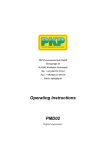
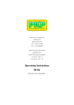
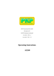
PKP Prozessmesstechnik GmbH Borsigstraße 24 D-65205 Wiesbaden-Nordenstadt Tel.: ++49-(0)6122-7055-0 Fax: ++49-(0)6122-7055-50 Email: [email protected] Operating instructions PMD04 Digital manometer battery operated Table of content 1 2 3 4 5 6 7 8 9 10 11 12 13 Introduction Description of device Commissioning Pressure Connection Dimensions Parameter und LCD-Anzeige Programming Technical Data CE-Conformity Maintenance Troubleshooting Cleaning Disposal EC Declaration of Conformity 2 3 3 4 4 6 8 8 8 9 9 9 9 1 Introduction The digital manometer described in the operating instructions is designed and produced in line with the most recent developments. All components are subject to the strictest quality criteria during production. These operating instructions have been compiled with care. However, it is impossible to take every possible usage case into consideration. For this reason, if you feel that instructions for your particular usage case are missing, please contact us, and we would be pleased to provide assistance. Please observe the relevant national safety regulations during the installation, start-up and operation of this digital manometer (e.g.: VDE 0100). Scope These instructions apply to the PMD04 series of digital manometers. Distinctions are drawn between the PMD04.1 and PMD04.2 models in the individual sections. The state of technology at the time of delivery always applies. PKP reserve the right to make technical changes without notice. Copyright All rights to these operating instructions are reserved. These operating instructions, including extracts thereof, must not be copied or translated into other languages without written permission. Safety instructions and warnings Please read these instructions before installing and starting up the digital manometer. Failure to follow the instructions will make all guarantee, warranty and compensation claims null and void. • Please ensure that the digital manometer is suitable for your application. • Please check that the materials that come into contact with the medium are compatible with the media that are going to be measured. • Perfect function and operating reliability of the device can only be guaranteed for the values specified in the technical data sheet. PMD04 Operating instructions 102011 page 2 Only qualified persons are permitted to install the equipment and make the electrical connection, and the correct tools must always be used. • Damaged devices must not be started up. If damage occurs during operation, suitable measures must be taken to prevent persons or property from being put at risk by the damaged • digital manometer. • The manometer must only be repaired by PKP. The accepted technical regulations and all national regulations must always be observed and complied with • Exclusion of liability PKP guarantees that the digital manometer is in perfect working condition when it is delivered. The basis consists of the technical data in the data sheet and these operating instructions. Liability cannot be accepted for the suitability of the digital manometer. Usage for any other purpose than the ones that are mentioned in „Correct purpose of use“ is not permitted. Claims for compensation will only be entertained by PKP in the event of intent or gross negligence. Responsibility for damage to equipment, systems or the surroundings of the digital manometer will not be accepted. No liability is accepted for damage caused by incorrect operation. The haulage contractor is responsible for damage that occurs in transit. 2 Description of device The digital manometer is available in two versions (models PMD04.1 and PMD04.2) for the most varied areas of use. The digital manometer offers the user numerous measuring units (bar, psi and MPa). Additional functions such as MIN/MAX memory, tare adjustment plus bar graph with trailing pointer function round off the digital manometer’s profile. The programmable parameters are adjusted by means of user-friendly keys on the front. Correct purpose of use The equipment is only authorised for proper use for its correct purpose. Failure to do this will invalidate all warranties and release the manufacturer from all responsibility! The equipment is constructed in compliance with IP65 and should be protected from excessive amounts of water and dust. The equipment must be installed so that it is protected from external damage. It must be ensured that the manometer is correctly installed and has the relevant IP protection. The limits specified in the data sheet must be complied with. 3 Commissioning Installation The digital manometer must be connected to the pressure tapping point in a suitable manner using your own tools. In this case there must be no occurrence of pressure which exceed the device’s maximum pressure values. Pressures which exceed the digital manometer’s maximum range can lead to permanent damage to the measuring device. When screw-fitting the gauges the force required for this must not be applied through the case or terminal box but just through the spanner flats (with suitable tool) provided for this purpose. For the assembly the moment of 25 Nm for G 1/4 connection may not be exceeded. PMD04 Operating instructions 102011 page 3 Power supply The digital manometer is operated with 2 Mignon AA batteries. The charge of the battery is indicated by the symbol A flashing battery symbol appears on the display screen if the battery charge is low and the batteries should then be replaced as soon as possible. Open the battery compartment lid on the back of the digital manometer. Replace the batteries with 2 new Mignon cells. Replace the battery compartment lid. 4 Pressure Connection Dimensions 5 Parameter und LCD-Anzeige LCD display of model PMD04.2 LCD display of model PMD04.1 PMD04 Operating instructions 102011 page 4 Funktion im Normal Modus Key Function • • • switches the device on switches the device off changes to programming mode if pressed for longer than 3 secs • display indicates MAX value as long as key is pressed • display indicates MIN value as long as key is pressed + • resets MAX value to 0 + • resets MIN value to 0 MIN/MAX memory The MIN/MAX memory is updated with the current measured value in every measuring cycle. The MIN value is displayed by pressing the MIN key. The MAX value is displayed by pressing the MAX key. Pressing and holding the appropriate key (MIN or MAX) and quickly pressing the menu key at the same time resets the device to the current measured value. Bar Graph with Trailing Pointer Function The integrated bar graph display with trailing pointer function additionally indicated on the display shows the trend in current working pressure directly regardless of the digital display. With the help of the trailing pointer function, the MAX stored value is also indicated in the bar graph display in addition to the digital display in the form of a bar segment. This bar segment is also updated to the current measure value when the MIN/MAX value is reset. PMD04 Operating instructions 102011 page 5 6 Programming Model PMD04.2: PMD04 Operating instructions 102011 page 6 Tare Function Model PMD04.2: In this mode the positive deviation of the measured value from the tared value (max. 20% of the measuring range) is constantly indicated by the main display. The untared pressure value is always shown on the bar graph display. Thus the digital manometer’s actual working load can be read off even if the tare function is active. When the tare function is active, a function indicator appears on the display. There are 2 possible ways of activating this mode: a) Select the tare function and set the value to be tared using the keys and . When set, the measured value to be tared is backed up as tare. The main display and the auxiliary display then show the value “0000” in the unpressurised state. Example: If a value to be tared is set as 2 bar, the main display indicates 1 bar when the actual pressure is 3 bar. b) Load the digital manometer with the pressure to be tared. The current measured value appears in the main display field of the main display. Select the tare function and then operate both keys simultaneously and . The current measured value will be backed up as tare. The main display and the auxiliary display are set to (0000). Setting the tare value to 0000 resets the tare function in both models. Model PMD04.1: PMD04 Operating instructions 102011 page 7 7 Technical Data Housing: Stainless Steel, 80 mm diameter Materials in contact with medium Up to 50 bar: SS, Al2O3, NBR, Measuring cell: ceramik From 100 bar: Stainless Steel, Measuring cell: thin film type Powersupply: 2 x 1,5 V round cell AA 4000 h (with 2000 mAh AA battery) Connection: G 1/4 B Accuracy: ± 0,5 % FS, ± 1 Digit Conversion rate: 5 cycles per second Units: bar, MPa, PSI adjustable Temperature ranges: - Compensation: - Storage: - Medium: - Ambient: 0 ..+60 °C -20 ..+70 °C -30 ..+ 85 °C (+ 100 °C from 100 bar) -10 ..+60 °C Temperature influence: max. ± 0,15 % / 10 K Overload limit: 2-fold (range A104: max 1000 bar) Protection class: IP 65 Emitted interference: according to EN 61326 Interference immunity: according to EN 61326 Weight: approx. 400 g 8 CE-Conformity The digital manometer complies with all requirements of EN 61 326 with regard to interference emission and immunity for use in industrial areas. Installation must be carried out correctly in order to maintain the effective protection from electromagnetic interference. 9 Maintenance The digital manometers that are described in this document are maintenance free. The equipment will also operate in a stable state for long periods, meaning that regular adjustment or the like is not required. PMD04 Operating instructions 102011 page 8 10 Troubleshooting No modifications must be made to the equipment. Only the manufacturer is allowed to repair the device. 11 Cleaning The exterior of the digital manometer can be cleaned using a soft, moistened cloth. Heavy soiling can be removed using a mild cleaning agent. The switch must not be opened for cleaning! Aggressive chemicals or hard scrubbing can damage the surface, particularly the display film. 12 Disposal Die Entsorgung der Verpackung und der verbrauchten Teile hat gemäß den Bestimmungen des Landes, in dem das Gerät installiert wird, zu erfolgen. 13 EC Declaration of Conformity We declare under our sole responsibility, that the CE marked products model PMD04, digital manometer according to the actual leaflet fulfills the essential requirements of the directives 97/23/EC and 89/336/EEC (EMC). The devices have been tested according to the EMC norm EN 61326:2004. PMD04 Operating instructions 102011 page 9 Pressure Measurement and Monitoring PMD04 Digital manometer battery operated • LCD display wtih 11 mm digit height • independent of additional power supply • Measuring range from 0..2 bar to 0..700 bar • Bar graph display with trailing pointer function • Non volatile MIN/MAX memory, keeping values even while changing batteries • Automated turn-off delay • Also with display lighting Description: Model series PMD04 digital manometers are independent of additional power supply, therefore suitable for a variety of applications. Thanks to innovative power saving technology average battery life is increased up to 4000 hours. A ceramic or thinfilm type measuring cell transforms the pressure of the medium to an electrical signal which is visualized on the display in user adjustable units, bar, PSI or MPa. Especially the bar graph display can be used particularly advantageous in industrial plants to read out even at larger distances the tendency of the measured value. Optionally a display lighting and a rotatable conection is available. PKP Process Instruments Inc. 10 Brent Drive Hudson, MA 01749 S +1-978-212-0006 • +1-978-568-0060 Email: [email protected] • Internet: www.pkp.eu Applications: These digital manometers are suitable especially for: - Mechanical engineering - Plant engineering - Hydraulic and pneumatic systems - Monitoring of measurement devices PKP Prozessmesstechnik GmbH Borsigstr. 24 • D-65205 Wiesbaden S +49 (0) 6122-7055-0 • +49 (0) 6122 7055-50 Email: [email protected] • Internet: www.pkp.eu Measuring Ranges: Measuring range (bar) Model Coding: Order code 0..2 A71 0..5 A121 0..10 A75 0..20 A77 0..50 A785 0..100 A81 0..160 A82 0..250 A84 0..400 A86 0..600 A87 0..700 A104 Dimensions: Order number: Digital manometer with LCD display PMD04 .1 .A75 .0 Design: 1 = Standard design 2 = With display lighting, adjustable turn-off delay, 4 1/2 digit display, Second Display 4 1/2 digits 7 mm height, Rotatable Measuring range: see table measuring ranges Options: 0 = None 9 = Please indicate Technical Details: PKP Process Instruments Inc. 10 Brent Drive Hudson, MA 01749 S +1-978-212-0006 • +1-978-568-0060 Email: [email protected] • Internet: www.pkp.eu Housing: Stainless Steel, 80 mm diameter Materials in contact with medium Up to 50 bar: SS, Al2O3, NBR, Measuring cell: ceramik From 100 bar: Stainless Steel, Measuring cell: thin film type Powersupply: 2 x 1,5 V round cell AA 4000 h (with 2000 mAh AA battery) Connection: G 1/4 B Accuracy: ± 0,5 % FS, ± 1 Digit Conversion rate: 5 cycles per second Units: bar, MPa, PSI adjustable Temperature ranges: - Compensation: - Storage: - Medium: - Ambient: 0 ..+60 °C -20 ..+70 °C -30 ..+ 85 °C (+ 100 °C from 100 bar) -10 ..+60 °C Temperature influence: max. ± 0,15 % / 10 K Overload limit: 2-fold (range A104: max 1000 bar) Protection class: IP 65 Emitted interference: according to EN 61326 Interference immunity: according to EN 61326 Weight: approx. 400 g PKP Prozessmesstechnik GmbH Borsigstr. 24 • D-65205 Wiesbaden S +49 (0) 6122-7055-0 • +49 (0) 6122 7055-50 Email: [email protected] • Internet: www.pkp.eu 102011