1
PKP Prozessmesstechnik GmbH
Borsigstrasse 24
D-65205 Wiesbaden-Nordenstadt
Tel: 06122 / 7055 - 0
Fax: 06122 / 7055 – 50
Operating Instructions
DV04
High - precision
Gearwheel flow meter for
viscous liquids
Contents
1 Introduction
2
2 Safety Information
2
3 Functional Description and Design
3
4 Special Conditions
4
5 Installation and Removal of the Gearwheel Flow Meter
4
6 Corrosion Protection
4
7 Mechanical Installation
5
8 Electrical Connection
6
9 Maintenance and Cleaning
7-8
10 Returning
9
11 Disposal
9
12 Troubleshooting
10
13 Dimensions
11-13
14 Specification
See data sheet in the appendix
1 Introduction
Series DV04 gearwheel flow meters are noted for their reliable function and easy operation.
To obtain the greatest benefit from this device, please observe the following cautionary
statement:
Persons who are responsible for setting up or operating this device must be sure to read
the and understand the operating instructions and the safety information pertaining to
it.
2 Safety Information
2.1 General Instructions
To ensure safe operation, the device must only be operated according to the information in the
operating instructions. When the device is in use, the regulations and safety standards
applicable to the specific application must also be observed. This statement also applies to the
use of accessories.
2.2 Proper Usage
Series DV04 gearwheel flow meters are designed for the continuous measurement of the flow
of low viscous fluids.
Any application extending beyond this specific intended use does not constitute proper usage.
Series DV04 must not be employed as the sole means of avoiding hazardous conditions in
machinery and installations.
The machinery and installations must be designed in such a manner that faulty conditions and
malfunctions will not present hazardous situations for operating personnel.
DV04-B~2.SAM
15.09.05
Page 2
2.3 Qualified Personnel
Series DV04 must only be used by qualified, knowledgeable personnel trained in correct use
of these devices. Qualified personnel are those persons familiar with setting up and
assembling these devices, placing them in service and operating them. In addition, such
personnel must also be qualified to perform the work associated with the application for
which the device is being used.
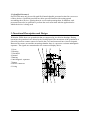
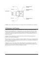
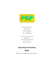
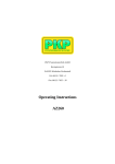
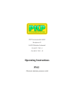
3 Functional Description and Design
Within the DV04 there two gearwheels that are supported in low-friction bearings. During
operation, the gearwheels are driven by the flowing liquid. The movement of the gearwheels is
sensed by two non-contact sensors located in the cover and converted into electrical signals.
Between the sensor area and the measuring chamber there is a pressure-resistant antimagnetic
separator. The signals are transmitted to the connected display device.
1 Cover
2 Housing
3 Gearwheel
4 Journal
5 Bearing
6 Anti-magnetic separator
7 Sensor
8 Device connector
9 O-ring
DV04-B~2.SAM
15.09.05
Page 3
4 Special Conditions
Special conditions and/or limitations apply to the safe application of gearwheel flow meters in
the approved operating environment. These conditions and/or limitations must be met by the
customer and/or system operator by means of appropriate technical and/or organizational
measures.
Gearwheel flow meters must only be operated in the specified environment and under the
specified ambient conditions.
Gearwheel flow meters must only be used if the materials used in their construction are
resistant to mechanical and/or chemical influences or corrosion under the given service
conditions.
The fluid must at least have minimum lubricating properties (lubricity).
Gearwheel flow meters are intended for use with liquids. Dry operation is not approved.
Operation outside of the specified parameters is not allowed.
If necessary, a filter must be installed to prevent the gearwheel from being blocked by foreign
objects.
The specified installation, service and maintenance schedules must be strictly followed.
Gearwheel flow meters must only be used in closed operation and not be subject to excessive
vibration.
Only genuine spare parts must be used for service and maintenance.
5 Installation and Removal of the Gearwheel Flow Meter
This gearwheel flow meter was thoroughly tested and checked at the factory before shipment.
It will be fully functional and immediately ready for use after it has been installed in position
and the electrical lines have been connected. The space required by the installed device is
specified in the "Dimensions" section. Once installed, the measuring device should also be
accessible for safe, visual inspection at any time.
Caution: To prevent possible damage to the gearwheel flow meter, a pressure regulating
device must be present in the installation to prevent the maximum permissible pressure from
being exceeded in the volume sensor or other parts of the installation (pressure-limiting
valves). During transport and installation, the gearwheel flow meter must only be held by its
housing; must never be suspended from the plugged-in connector!
6 Corrosion Protection
All gearwheel flow meters are checked for proper function at the factory with mineral-based
hydraulic oil. Following testing, the connections are sealed with plugs so that the internal parts
are protected against corrosion for a moderate amount of time. During transport and storage,
gearwheel flow meters must not be exposed to the harmful effects of ambient weather
conditions and great variations in temperature. They must be stored under dry conditions.
If a gearwheel flow meter is to be stored for a longer period of time, both its interior and
exterior must be protected by application of a suitable anti-corrosion oil. In addition, it must
be protected from humidity by means of a desiccant material.
If high humidity or other unfavorable (aggressive, polluted) ambient conditions are expected
to be encountered during transport, appropriate steps must be taken to prevent corrosion of
the gearwheel flow meter.
DV04-B~2.SAM
15.09.05
Page 4
Caution: When applying an anti-corrosion treatment, first check to be sure that the material to
be used is compatible with the elastomers used in the construction of the gearwheel flow
meter and will not harm them. You should also check that the material used is compatible
with the fluid flowing through the flow meter.
7 Mechanical Installation
Depending on the installation, the device is connected to the system by means of a connection
plate or pipe connections in its housing.
Caution: Only piping and connections that are approved for the expected pressure range may
be used. The specifications of the respective manufacturer must be followed. The device must
be installed so that it is not subject to excessive vibration. Installation above hot parts is not
allowable since liquids that could possibly leak from the device may then be ignited. When
being placed in operation, the device must be checked for leaks under normal operating
conditions.
Connection Plate
Before installing the gearwheel flow meter, carefully clean the piping system. Then mount the
connection plate at the prescribed location in the system.
Caution: Make sure that the gaskets are seated properly! The joint surface must be free of dirt
and paint residue
Place the housing on the connection plate so that the mounting holes are in alignment.
Fasten the housing to the connection plate with the screws and tighten them down.
Caution: The mounting screws for the DV04 mountings plate must be tightened crossways.
Be sure to apply the correct amount of torque.
Installation on connection plates not supplied with the device or on valve manifolds
Be sure to observe the specified values for surface flatness and surface roughness.
Nominal size
Surface roughness R t 1/ 1000 mm
Surface flatness
1/ 1000 mm
DV04.2-6
DV04.7-8
0.01
0.02
10
10
In this case, the gearwheel flow meter must also be installed as described above.
DV04-B~2.SAM
15.09.05
Page 5
Pipe Connection
Before installing the gearwheel flow meter, completely clean the piping system.
Connect the piping to the inlet and outlet of the measuring device. Be sure to observe the
specifications of the respective manufacturer.
During installation be sure than no sealant gets inside the piping system.
Caution: The gearwheel flow meter must not be subjected to excessive mechanical stress
during installation.
After the gearwheel flow meter is installed and the piping system is placed back in service,
check all connections for leakage.
8 Electrical Connection
Number of measuring channels
Operating voltage
Pulse amplitude
Pulse from with symmetric output signal
Pulse offset between both channels
Power consumption
Output power / channel
Protection type
2
UB = 24 V DC +/- 20%, protected against
polarity reversal
UA >/= 0,8 UB
Square-wave pulse, scanning ratio
/channel 1:1 +/- 15%
90° +/- 30°
Pb max = 0,9 W
Pa max = 0,3 W, short circuit proof
IP 65 (DIN 40500)
Prerequisite:
A 24V (DC) line (± 20 %) must be provided to supply power to the pre-amplifier.
The terminal assignment for channel 1 or 2 has an influence on the displayed direction of
rotation of the gearwheels, and thus on the preceding sign (+ or -) that is used when
displaying the measured volumetric flow rate on the evaluation device.
DV04-B~2.SAM
15.09.05
Page 6
Caution: After assembly, the mounting screw (slightly) and the cable gland nut must be tightened
9 Maintenance and Cleaning
Gearwheel flow meters are generally maintenance-free. However, if fluids that can leave
deposits flow through the device, cleaning may be necessary. Otherwise, the device can be
cleaned with the rest of the system during the standard cleaning procedure. Indications of
wear may be evident by a change in measuring accuracy. It is recommended the device be
inspected regularly.
Caution: If fluids harden in the gearwheel flow meter, it must be cleaned as quickly as
possible with suitable cleaning agents.
The mounting screws must be regularly checked for tightness. If necessary, retighten them (in
such case, observe the tightening torque specified in the section ”Installation and Removal of
the Gearwheel Flow Meter”).
Caution: Be sure to relieve the pressure in the piping before performing any work on the
gearwheel flow meter or removing it. The gaskets in the joints between the gearwheel meter
and the piping system must be checked regularly for leakage.
DV04-B~2.SAM
15.09.05
Page 7
Cleaning
Devices in series 1, 2, 6, 7 and 8:
These devices must never be opened by the customer. They must only be opened by trained
service personnel because only such specialists can reassemble them properly so that they will
function correctly.
Devices in series 3, 4 and 5:
If due care is used, these devices may be opened and cleaned by the customer.
Caution: Be sure to relieve the pressure in the piping and ensure that the electrical supply is
de-energized before opening and cleaning the device. The device and the piping may still
contain the transported fluid or a cleaning agent. All guidelines governing the handling of the
fluid that was last sent through the system must be followed. Before opening the system,
make sure that containers of sufficient capacities are available to catch any escaping fluid. If
necessary, the work area must also be sufficiently ventilated.
Removing the gearwheel flow meter (see section ”Installation and Removal of the
Gearwheel Flow Meter”).
Drain the measuring device.
Loosen the screws that hold the two halves of the housing together bolts.
The 4 or 8 internal hexagon drive screws ("Allen screws) are accessible from the bottom of
the housing.
Caution: When removing the upper half of the gearwheel flow meter, do not pry the halves
apart at the joint with screwdrivers or similar tools. The gearwheels must not be removed from
the housing with pliers or similar tools.
Clean the interior of the housing, the gearwheels and the bearings with a suitable cleaning
agent.
Insert both gearwheels with the bearings in the lower housing.
Position the o-ring in the grooved seat in the housing.
Place the upper part of the housing on the bottom part (insert the locating pins).
Insert the screws and snug them down crossways. Then tighten them crossways to the
specified torque (see below).
Caution: All parts being assembled must be free of dirt and deposits. During installation of the
gearwheel flow meter, make sure that no foreign objects enter the assembly.
Nominal Size*
Tightening Torque Nm
DV04.
2
14
DV04. DV04.
3
4
14
14
DV04.
5
35
DV04. DV04.
6
7
35
120
DV04. DV04.
9
8
120
290
Install the housing again in the system as described in the section ”Installation and Removal
of the Gearwheel Flow Meter”.
DV04-B~2.SAM
15.09.05
Page 8
10 Returning
If service or repair to the device is necessary or if the device needs to be inspected at the
factory, it must be suitably packed for shipment. Furthermore, the device must be
accompanied by a material safety data sheet indicating the fluid that was used in it. In the case
of common mineral oils, an exact type designation is required.
Caution: If the device was used with fluids whose residues will become hard or sticky, it must
be rinsed out before being returned.
11 Disposal
The device packing material as well as used devices and device parts must be disposed of in
accordance with applicable regulations of the country in which the device is installed.
DV04-B~2.SAM
15.09.05
Page 9
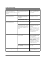
12 Troubleshooting
Error
Possible cause
Remedy
The two LED displays on the
isolating switch amplifier are
illuminated, but incorrect values are
displayed.
The connection between gearwheel
flow meter and evaluation device is
faulty.
Check the connection and, if
necessary, replace the cable or
plug connector.
One of the LED displays does not
illuminate during operation.
The wiring between the sensor and
the circuit board or individual
soldered points on the circuit board
are damaged.
Return the measuring device to
the manufacturer for repair.
The associated sensor is faulty.
The two LED displays do not
illuminate during operation.
Leakage, fluid leak
No voltage supply present
Check the power cable and
fuses.
Since it is unlikely that both sensors
will fail at the same time, it should
then be assumed that the measuring
mechanism has stopped for some
reason.
Immediately remove the
gearwheel flow meter from
operation!
Return devices in series 1, 2, 6,
7 and 8 to the manufacturer for
repair.
Devices in series 3, 4 and 5 may
be disassembled and cleaned
(see "Maintenance").
O-ring in housing defective,
allowing leakage.
Return devices in series 1, 2, 6,
7 and 8 to the manufacturer for
repair and request advice on the
specific application.
Check devices in series 3, 4 and
5 for seal compatibility with the
particular fluid being
transported. If necessary contact
the manufacturer and install a
new gasket set (can be ordered
from the manufacturer).
O-ring between gearwheel flow
Check seal compatibility, install
meter and connection plate defective, new O-rings.
allowing leakage.
Reduced measuring accuracy
DV04-B~2.SAM
Device wear
Check measuring device or
return to the manufacturer for
repair.
15.09.05
Page 10
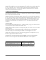
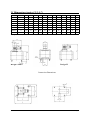
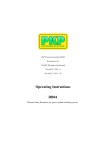
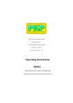
13 Dimensions (series 1,2,3,4,7)
Model
Weight*
A
C
D
F
GS
GH
J
K
L
M
N
P
DV04.2
1,8
85
10
60
50
101
114
-
70
40
20
6,5
M6
DV04.3
2
85
9
60
56
107
120
-
70
40
20
6,5
M6
DV04.4
2
85
13
60
57
108
121
-
70
40
20
9
M6
DV04.5
3,7
100
17
90
63
114
127
-
80
38
34
16
M8
DV04.6
5,2
120
13
95
72
123
136
15,5
84
72
35
16
M8
DV04.7
9
170
18
120
89
140
153
46,5
46
95
50
25
M12
DV04.8
13
170
22
120
105
156
169
46,5
46
95
50
25
M12
DV04.9
35,5
200
25
160
121
172
-
-
64
125
70
38
M16
* in Kg
Design S and X
Design H
Connection Dimensions
DV04-B~2.SAM
15.09.05
Page 11
Dimensions (series 5,6,8, stainless steel version)
Model
Weight*
C
D
F
GS
GH
J
K
L
M
N
P
DV04.2
3
15
94
55
106
119
-
70
40
20
6,5
M6
DV04.3
3
9
94
56
107
120
-
70
40
20
6,7
M6
DV04.4
3,1
13
94
57
108
121
-
70
40
20
9
M6
DV04.6
7
13
124
72
123
136
15,5
84
72
35
16
M8
DV04.7
15,9
21
170
89
140
153
46,5
46
95
50
25
M12
DV04.8
18,7
25
170
105
156
169
46,5
46
95
50
25
M12
* in Kg
Design S and X
Design H
Connection Dimensions
DV04-B~2.SAM
15.09.05
Page 12
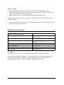
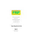
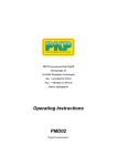
Connection flanges (cast iron)
Model
Weig..*
A
B
C
E
F
G
H
J
K
L
M
N
P
R
c
17
d
e
f
DV04.2-DV04.4
1,8
85
90
35
65
76
7
11
7
70
40
20
6,5
M6
0,7
25
G3/8
13
DV04.5
2,7
100 110
37
86
96
7
11
7
80
38
34
16
M8
18,5 0,7
29
G1/2
15
DV04.6
2,9
100 120
37
80
106
7
11
7
84
72
35
12
M8
17,5 0,7
29
G1/2
15
DV04.7
4,9
100 120
65
80
106
7
11
8
84
72
35
13
M8
32,5
1
42
G1
19
80
140 145
G1
19
DV04.8
14
160 165
9
15
9
46
95
50
25
M12
28
1
42
DV04.9
28
200 215 100 176 191 11
18
11
64
125
70
38
M16
35
1
58
G 1 1/2 23
* in kg
View X
DV04-B~2.SAM
15.09.05
Page 13
DV04-B~2.SAM
15.09.05
Page 14
Flow Measurement and Monitoring
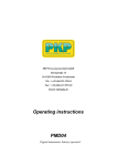
DV04
High-precision Gearwheel
flow meter for viscous liquids
• F or fluids with viscosities
of at least 20 cSt
• Very cost effective
• C
ast iron or stainless steel
designs available
• A
ccuracy better than 0.3%
of measured value
• High resolution
• P
ressure-proof construction
withstands up to 400 bar
• Small installation dimensions
Description:
Applications:
The measuring mechanism in the DV04 flow meter consists
of a pair of gearwheels that are driven by the fluid stream,
much like a gearwheel pump. The measuring mechanism is
supported by sleeve bearings or ball bearings. Two antimagnetic sensors, with a relative phase offset of 90° and
hermetically isolated from the measuring chamber, sense
the movement of the gear wheels. This two-channel sensing
system used with appropriate electronics permits a higher
measurement resolution as well as detection of flow direction. All flow meters are optionally available in a explosionproof design with a separate switching amplifier. The DV04
gearwheel flow meter features very low resistance to flow
and particularly low sound pressure levels.
Their outstanding measuring accuracy and high resolution
make these devices particularly suitable for use in test
stands when measuring small and very small flow volumes.
PKP Process Instruments Inc.
10 Brent Drive · Hudson, MA 01749
S +1-978-212-0006 · T +1-978-568-0060
Email: [email protected] · Internet: www.pkp.eu
Other areas of application:
• Measuring consumption rates
• Controlling and regulating filling processes
• Dosing of oils and chemicals
• Flow measurement of paints and varnishes
• Controlling the ratio of polyalcohol/polyhydroxy alcohol
and isocyanate
PKP Prozessmesstechnik GmbH
Borsigstraße 24 · D-65205 Wiesbaden
S +49 (0) 6122-7055-0 · T +49 (0) 6122-7055-50
Email: [email protected] · Internet: www.pkp.de
10/11
Designs (table 1)
Model coding:
Depending on application and medium properties, the DV04
is available in 8 different model ranges:
Order number:
Series Material
Minimum
Accuracy
Medium properties
viskosity (% of mea2
(mm /s) sured value)Viskosity
Lubricity
1
GGG40
20
+/- 0.3 2
GGG40
50
+/- 0.5 average
good
3
GGG40
100
+/- 1.0 high
good
4
GGG40
100
+/- 0.5 average
low
5
stainless steel
100
1.4404 +/- 0.5 average
DV04.2: +/- 3
low
6
stainless steel
1.4404
7
8
20
low
+/- 0.3 good
low
good
GGG40
20
+/- 1 low
low
stainless steel
1.4404
20
+/- 1 low
low
Process connection (table 2)
Baureihe
bearing
1
2
5
4
Hard alloy Hard alloy
sleevesleevebearing
bearing
3
bronze
sleevebearing
7
6
Hybridballball
bearing bearing
8
Hybridball
bearing
Type
ballbearing
DV04.2
G 3/8
-
-
-
G 1/8
G 1/8
G 3/8
G 1/8
DV04.3
G 3/8
-
-
-
-
G 1/4
G 3/8
G 1/4
DV04.4
G 3/8
G 3/8
-
G 3/8
G 3/8
G 3/8
G 3/8
G 3/8
DV04.5
G 1/2 or
G 3/4
-
-
G 1/2 or
G 3/4
-
-
-
-
DV04.6
G 1/2 or
G 3/4
G 1/2 or
G 3/4
G 1/2 or
G 3/4
G 1/2
G 1/2
DV04.7
G1
G1
G1
G1
G1
-
-
DV04.8
G1
G1
G1
G1
G1
-
-
DV04.9
G 1 1/2
-
-
-
-
-
-
-
DV04.10
G 1 1/2
-
-
-
-
-
-
-
ballbearing
G 1/2 or
G 3/4
G1
G 1/2 or
G 3/4
G 1/2
Measuring ranges in l/min (table 3)
Model
1
3
4
DV04.2 0,008-2
-
-
-
DV04.3 0,02-4
-
-
-
-
0,16-16
5
6
7
8
0,02 - 2 0,008-2 0,008-2 0,008-2
-
0,02-4
0,02-4
0,02-4
0,16-16 0,16-16 0,16-16 0,16-16
-
-
0,2-30
-
-
-
-
DV04.6 0,4-80
0,4-80
0,6-40
0,3-60
0,3-60
0,4-80
0,4-80
0,4-80
0,6-100 0,6-160
-
0,6-100
-
-
DV04.8 1-250
1-250
1,2-80
1-160
1-160
1-250
-
-
DV04.9 2-600
-
-
-
-
-
-
-
DV04.10 3-700
-
-
-
-
-
-
-
Parameters (table 4)
Model
Maximum
pressure
(bar)
Measuring ranges:
2…9 = as per table 3
Series:
1…8 = as per table 1
Seal:
F = Viton
E = EPDM
P = PTFE / Kalrez
Connection:
PS = with mounting plate, connection at the side
PU = with mounting plate, connection at bottom
R = without mounting plate, connection at the side
(model ranges 5, 6, 8 only)
Process connection (see table 2):
04 = G 1/8 IG
05 = G 1/4 IG
10 = G 3/8 IG
15 = G 1/2 IG
20 = G 3/4 IG
25 = G 1 IG
40 = G 1 1/2 IG
Electronics:
S = Standard
H1 = High-temperature-design up to 150 °C
H2 = High-temperature-design up to 220°C (FEP-Gasket
and clamp-connection)
X = Intrinsically safe with separate switching amplifier (EEx ia IIC)
Special features:
0 = None
1 = Please specify in writing
Technical details:
DV04.5 0,2-40
DV04.7 0,6-160 0,6-160
Gearwheel flow meter
Range
2
DV04.4 0,16-16 0,16-16
DV04 3. 1. F. PS.. 10. S. 0
Peak
pressure
(bar)
Sound pressure Resolution
level
impulses / l
(dB(A))
DV04.2
400
480
< 60
40.000
DV04.3
400
480
< 60
25.000
4.081,63
DV04.4
400
480
< 60
DV04.5
400
480
< 70
2.500
DV04.6
400
480
< 70
965,25
333,33
DV04.7
315
350
< 70
DV04.8
315
350
< 72
191,5
DV04.9
400
480
< 80
83,33
DV04.10
400
480
< 80
62,5
PKP Prozessmesstechnik GmbH
Borsigstraße 24 · D-65205 Wiesbaden
S +49 (0) 6122-7055-0 · T +49 (0) 6122-7055-50
Email: [email protected] · Internet: www.pkp.de
Viscosity range:20 to 100000 mm2/s
Pressure loss:depends on viscosity and load on
the device (exact values available
upon request)
Temperature range:
Standard design:−30... +120 °C
High-temperature
design:−30...+150 °C
Materials:
Series 1-4, 7:housing GGG 40, GGG60
(DV04.9, DV04.10)
Measuring mechanism 1.7139
Series 5, 6, 8:housing stainless steel 1.4404
Measuring mechanism
stainless steel 1.4462
Electronics:
Standard:2 sensors, 90° phase
offset
Ex-design:with separate
switching amplifier
Supply voltage: 12…30 VDC,
Protected against polarity reversal
Output signal: Square-wave pulse, minimum
0.8*UB, Scanning ratio 1:1
(± 15%)
Protection type: IP 65
PKP Process Instruments Inc.
10 Brent Drive · Hudson, MA 01749
S +1-978-212-0006 · T +1-978-568-0060
Email: [email protected] · Internet: www.pkp.eu