1
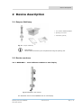
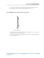
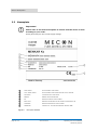
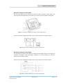
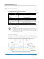
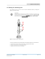
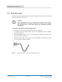
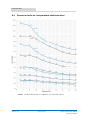
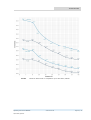
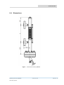
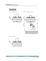
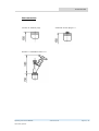
MENKAR Level Indicator
Operating instructions
© MECON GmbH 06/2012 OI_Menkar
Imprint
All rights reserved. It is probibited to reproduce this documentation, or any other there of,
without the prior written authorisation of MECON Flow Control Systems GmbH.
Subject to change without notice.
Copyright 2012 by
MECON Flow Control Systems GmbH - Röntgenstraße 105 - 50169 Kerpen
Page 2 / 32
www.mecon.de
Operating instructions MENKAR
06/2012 OI_Menkar
Contents
Contents
1 Safety instructions _______________________________________________ 5
1.1 General information ..................................................................................... 5
1.2 Disclaimer ................................................................................................... 5
1.3 Product liability and warranty ........................................................................ 5
1.4 Safety instructions for the operator ................................................................ 6
2 Device description _______________________________________________ 7
2.1 Scope of delivery ......................................................................................... 7
2.2 Device versions ........................................................................................... 7
2.2.1 MENKAR K -
Level indicator without on site display ............................ 7
2.2.2 MENKAR KM – Level indicator with magnet flapper type indicator........... 8
2.2.3 MENKAR KA – Level indicator with on site display ................................ 9
2.3 Nameplate ................................................................................................ 10
2.4 Description code ........................................................................................ 11
3 Installation ____________________________________________________ 13
3.1 Installation conditions................................................................................. 13
3.2 Mechanical installation conditions ................................................................. 13
3.3 Storage .................................................................................................... 13
4 Magnetic connections ____________________________________________ 14
4.1 Safety instructions ..................................................................................... 14
4.2 Types of contact systems ............................................................................ 14
4.2.1
Reed gas contacts ......................................................................... 14
4.2.2
Inductive slot initiators .................................................................. 16
4.3 Setting the switching point .......................................................................... 17
4.4 Protection class.......................................................................................... 18
5 Operation _____________________________________________________ 19
5.1 Operating principle ..................................................................................... 19
5.2 True level indication ................................................................................... 19
5.3 Changing the process conditions .................................................................. 20
6 Service _______________________________________________________ 21
6.1 Maintenance .............................................................................................. 21
6.2 Returning the device to the manufacturer ..................................................... 21
6.3 Disposal .................................................................................................... 22
Operating instructions MENKAR
06/2012 OI_Menkar
www.mecon.de
Page 3 / 32
Contents
7 Application ____________________________________________________ 23
8 Project development ____________________________________________ 24
9 Technical Data _________________________________________________ 25
9.1 Pressure limits vs. temperature stainless steel ................................................ 26
9.2 Certifications............................................................................................... 28
9.3 Classification according to Directive (PED) 97/23/EC ........................................ 28
9.4 Dimensions ................................................................................................. 29
Page 4 / 32
www.mecon.de
Operating instructions MENKAR
06/2012 OI_Menkar
Safety instructions
1 Safety instructions
1.1
General Information
Read the instructions carefully before installing the device and put it into operation.
This manual is intended for correct installation as well as operation and maintenance
of the devices.
Specially designed or customised models and specialised applications are not included
in this manual.
1.2
Disclaimer
The manufacturer will not be liable for any damage using its product, including, but
not limited to direct, indirect incidental, punitive and consequential damages.
Any product purchased from the manufacturer is warranted in accordance with the
relevant product documentation and our Terms and Conditions of Sale.
The manufacturer reserves the right to revise the content of this document, including
this disclaimer, without prior notification and will not be liable in any way for possible
consequences of such changes.
1.3
Product liability and warranty
The Operator of these level indicators is responsible for the suitability, proper use and
corrosion resistance of the used materials with regard to the measuring material. It
must be ensured that the materials selected for the parts of the level indicator
coming into contact with the medium are suitable for the used process media. Mecon
GmbH can assume no guarentee for repair work carried out by the customer without
prior notification and consultation.
In this case of complaint, the rejected parts must be returned to us, if no other
arrangement has been made.
Operating instructions MENKAR
06/2012 OI_Menkar
www.mecon.de
Page 5 / 32
Safety instructions
1.4
Safety instructions for the operator
The effective pressure of the installation (the maximum permitted by the
pressure limiting valve) must never be greater than the maximum permitted
pressure Ps, marked on the instrument nameplate.
The user must be sure that materials in contact (guide tube, float, gaskets,
etc.) with the fluid used are compatible with the fluid and conform to ageing
characteristics of the fluid used and the measurement environment. These
have either been recommended in the instructions or form the subject of a
particular specification in the contract.
The external pressure (Pext) must be equal to atmospheric pressure (Patmos)
No external loads may act upon the device. The level indicator is primarily
designed for static applications.
Before replacing the standpipe/float, check that the unit is free from
hazardous media and pressures.
Page 6 / 32
www.mecon.de
Operating instructions MENKAR
06/2012 OI_Menkar
Device description
2 Device description
2.1 Scope of delivery
1 Level indicator MENKAR K/KM/KA
2 Operating instructions
3 Certificates (optional)
Fig. 2.1
Scope of delivery
Information!
Please check the delivery for completeness using the packing list.
2.2 Device versions
2.2.1 MENKAR K – Level Indicator without on site display
Fig. 2.2 MENKAR K with contacts
The standard version of the MENKAR has no local display.
Operating instructions MENKAR
06/2012 OI_Menkar
www.mecon.de
Page 7 / 32
Device description
For control systems (acoustic or optical signals, motor and valve control systems or
similar) magnetically actuated contact units are available.
The arrangemant of contacts is possible in any order and number (except for a
minimum distance).
2.2.2. MENKAR KM – Level Indicator with magnet flapper type indicator
Fig. 2.3
MENKAR KM (Standard device)
Fig. 2.4
MENKAR KM with contacts
The standard version of MENKAR KM has a local display by use of a magnetic flapper
type indicator (Fig. 2.3). The vertical movement of the float causes a color change of
the magnetic flapper corresponding to the level.
Optionally magnetically actuated contacts are available for the MENKAR KM (Fig.
2.4.) for control applications (acoustic or optical signals, motor and valve control
systems, etc.). The arrangement of these contacts is, apart from a minimum
distance, which is a result oft he desgin, possible in any order and number.
Fig. 2.5
Page 8 / 32
MENKAR KM with magnet flapper and percentage display
www.mecon.de
Operating instructions MENKAR
06/2012 OI_Menkar
Device description
Upon request the MENKAR KM is available with an additional percentage display for a
better readability of the local display (magnetic flapper) (see Fig. 2.5).
2.2.3 MENKAR KA- Level indicator with on site display
Fig. 2.6
MENKAR KA
The standard version of the MENKAR KA has a local display by use of an external
transparent tube display with a float (Fig.2.6).
The vertical movement of the measuring float causes a position change of the display
float corresponding the level.
Operating instructions MENKAR
06/2012 OI_Menkar
www.mecon.de
Page 9 / 32
Device description
2.3
Nameplate
Important!
Please refer to the device nameplate to ensure that the device is built
according to your order.
Check particulary for the correct supply voltage.
1
Code number
Device specific code number
2
Year / Serial number
Device specific serial number and the year it was built
3
Connection
Connection type of the device
4
Material
Material of the wetted parts
5
PS
Maximum pressure of the medium
6
Pmax at TS
Maiximum temperature of the medium at temperature TS
7
TS Medium
Maximum temperature of the medium
8
CE-Marking
Category acc. To Pressure Equipment directive (PED)
Fig. 2.7
Page 10 / 32
Nameplate MENKAR
www.mecon.de
Operating instructions MENKAR
06/2012 OI_Menkar
Device description
2.4 Description code
The decription code consists of the following elements:
Process connections
Nominal size
Axx
Bxx
Cxx
Dxx
Exx
Fxx
EN1092-1
DN 15
DN 20
DN 25
DN 32
DN 40
DN 50
Pressure rating
xDx
xEx
xFx
xGx
xPx
xHx
xJx
xKx
xLx
xMx
xNx
PN 40
PN 63
PN 100
PN 160
PN 250
150 lbs
300 lbs
600 lbs
900 lbs
1500 lbs
2500 lbs
(EN 1092-1)
(EN 1092-1)
(EN 1092-1)
(EN 1092-1)
(EN 1092-1)
(ASME B16.5)
(ASME B16.5)
(ASME B16.5)
(ASME B16.5)
(ASME B16.5)
(ASME B16.5)
Flange Form
1
xxA
xxB
xxC
xxD
xxG
xxH
xxJ
B1
B2
Form
Form
Form
Form
Form
(EN 1092-1)
(EN 1092-1)
(EN 1092-1)
(EN 1092-1)
(ASME B16.5)
(ASME B16.5)
(ASME B16.5)
WT1
WT2
WT3
WN1
WN2
WN3
Welding
Welding
Welding
Welding
Welding
Welding
2
Design
K
M
P
A
Menkar
Menkar
Menkar
Menkar
3
D
C
RF
FF
RTJ
K
KM
KM
KA
end
end
end
end
end
end
ANSI B16.5
½"
¾"
1"
1 ¼"
1 ½"
2"
PN 40
PN 100 - PN 250
PN 40 - PN 250
PN 40 - PN 250
150lbs - 2500lbs
150lbs - 2500lbs
150lbs - 2500lbs
DN 15 (Length 60 mm)
DN 20 (Length 60 mm)
DN 25 (Length 60 mm)
½ " (Length 60 mm)
¾ " (Length 60 mm)
1 " (Length 60 mm)
(without on site display)
(with magnet flapper display)
(with magnet flapper display and percentage display)
(with on site display)
Center distance
Center distance in mm
4
A
C
X
Z
Drain connection
Drain plug G ½
Bleed valve G ½
without
Special drain connection
Operating instructions MENKAR
06/2012 OI_Menkar
www.mecon.de
Page 11 / 32
Device description
5
A
B
C
Z
6
Ventilation
without (cap)
Screw plug G 1/2
Ventilation valve G 1/2
Special ventilation
Measuring float
1A
1B
1C
1D
04
10
11
1E
1F
1G
in
in
in
in
in
in
in
in
in
in
Titanium
Titanium
Titanium
Titanium
Titanium
Titanium
Titanium
Titanium
Titanium
Titanium
05
06
07
08
6A
7A
8A
in
in
in
in
in
in
in
W.Nr.
W.Nr.
W.Nr.
W.Nr.
W.Nr.
W.Nr.
W.Nr.
for
for
for
for
for
for
for
for
for
for
density
density
density
density
density
density
density
density
density
density
1.4571
1.4571
1.4571
1.4571
1.4571
1.4571
1.4571
for
for
for
for
for
for
for
0,40
0,51
0,61
0,71
0,76
0,81
0,91
0,51
0,61
0,71
density
density
density
density
density
density
density
– 0,500 kg/dm³
– 0,600 kg/dm³
– 0,700 kgdm³
– 0,795 kgdm³
- 0,835 kg/ dm³
– 0,900 kg/dm³
– 1,0 kg/dm³
- 0,600 kg/ dm³ pressure relieved
- 0,700 kg/ dm³ pressure relieved
- 0,795 kg/ dm³ pressure relieved
0,85
0,96
1,16
1,20
1,00
1,16
1,20
-
0,950
1,150
1,295
1,500
1,150
1,295
1,500
kg/
kg/
kg/
kg/
kg/
kg/
kg/
dm³
dm³
dm³
dm³
dm³ pressure relieved
dm³ pressure relieved
dm³ pressure relieved
Additional options
K01
K02
…
K09
1x contact KA 23
2x contact KA 23
….
9x contact KA 23
K11
K12
…
K19
1x contact KA 33
2x contact KA 33
….
9x contact KA 33
K21
K22
…
K29
1x contact KA 33i
2x contact KA 33i
….
9x contact KA 33i
M02
M03
…
M10
200mm electric remote transmitter 4-20mA (scanning 5mm)
300mm electric remote transmitter 4-20mA (scanning 5mm)
….
1000mm electric remote transmitter 4-20mA (scanning 5mm)
Page 12 / 32
www.mecon.de
Operating instructions MENKAR
06/2012 OI_Menkar
Installation
3 Installation
3.1
Installation conditions
•
The level indicator MENKAR must be installed vertically on the tank.
•
When installing the MENKAR level indicator with or without the electrical level transducer system, make sure that any magnetic fields generated by other equipment will
not affect the measurement.
•
Select bolts and gaskets (supplied by customer) that correspond to the pressure rating
of the connecting flange and the operating pressure.
The process connections (flanges) must fit perfectly, i.e. they must be centred, parallel
and bolted in a professional way, in order to avoid unneccessary mechanical stress on
the installation.
•
The tank must be free of contaminants. It is recommended to install shut-off elements,
e.g. taps, valves, etc. between the tank and the level indicator to allow the level
indicator to be cleaned independently of the tank. To simpilfy the cleaning procedure
the drain plug in the bottom flange could be replaced by a bleed valve with a discharge
line.
● Remove the transport securing device from the fitting.
● Verify prior to installation that the float slides smoothly in the fitting without canting or
deadlocking.
3.2
Mechanical installation conditions
•
The effective pressure of the installation (permitted by the pressure limiting valve)
must never be greater than the maximum pressure PS given on the nameplate of
the device.
•
The user has to ensure the compatibility of the materials in contact with the fluid
(guide tube, float, gaskets, etc.) and as well the conformity to ageing characteristics as the suitability to the measurement environment. This information is
either given in the operating instructions or it’s explicit specified in the contract.
•
3.3
The external pressure (Pext) must be equal to atmospheric pressure (Patmos).
Storage
•
Store the device in a dry and dust-free place.
•
Keep away from direct sun and heat.
•
Avoid external load to the device.
•
The storage temperature range for standard devices with electrical components is
about -40 … +70 °C / -40 … +158 °F.
Operating instructions MENKAR
06/2012 OI_Menkar
www.mecon.de
Page 13 / 32
Magnetic contact systems
•
4 Magnetic contact systems
4.1 Safety instructions
Warning!
All work on the electrical connections may only be carried out by a
specialist. Ensure that the power is disconnected.
Observe all occupational safety regulations unconditionally. It is essential to
regard the voltage data on the nameplate.
4.2 Types of contact systems
Either reed gas contacts or inductive slot initiators are available for the magnetic
contact system.
The reed gas contacts can be used directly as a passive switch in existing electric
circuits; the inductive contacts require an isolation amplifier.
4.2.1 Reed gas contacts
The magnetic contact system KA 23 and KA33 have
integrated reed gas contacts.
The electrical function of these two contacts is identical
– only the type of cable connection is different.
For technical data please refer to the following table.
Technical data
KA 23
Housing material
KA 33
Aluminium
Protection class
IP 65
Mounting
Clip on standpipe
Cable connection
PG 11
Connector acc.
EN 175301-803
Type of contact
Reed gas contact, potential free
Switching function
change over contact, CO
Contact material
Ag-Pd
Contact rating (max.)
AC: 250V eff./1A/150VA;
DC: 250V/1A/100W
Tab. 4.1 Technical data for contact systems with reed gas contact
Page 14 / 32
www.mecon.de
Operating instructions MENKAR
06/2012 OI_Menkar
Magnetic contact systems
Electrical connection of the KA23
The lid of the KA23 can be removed by loosen the four mounting screws. Insert the
cable via the cable gland and connect the wires to the screw terminals oft he KA23.
Fig. 4.1 Connection compartement of the contact system KA 23
For the connection assignment please refer to the following connection scheme.
Fig. 4.2 Connection scheme of the contact system KA 23
Electrical connection of the KA33
The electrical connection of the KA33 is compared to the KA23 made by a rectangular
connector according to EN 175301-803. Therefor it is not neccessary to open the
housing of the contact system.
For the connection assignment please refer to the following connection scheme.
Fig. 4.3
Operating instructions MENKAR
06/2012 OI_Menkar
Connection scheme of the contact system KA33
www.mecon.de
Page 15 / 32
Magnetic contact systems
4.2.2. Inductive slot initiators
Contact devices KA33i are equipped with inductive slot initiators of the type SJ3.5-N.
For technical data please refer to the following table.
Technical Data
KA 33i
Housing material
Aluminium
Protection class
IP 65
Mounting
Clip on standpipe
Cable connection
Connector acc. EN 175301-803
Switch type
SJ3,5-N
Switching function
NAMUR, NC
Voltage UO
8.2 V DC (Ri ca. 1 kΩ)
Supply voltage
Tab. 4.2
5 … 25 V DC
Technical Data for contact systems with slot initiators
Important!
The applied limit switches SJ3,5-N are NC contacts according to NAMUR
recommendation NE21. The desired switching function of the limit
switch has to be realized by the relay contact of the external isolation
amplifier (changeover contact).
Electrical contact KA33i
The electrical connection of the KA33i is in contrast to the type KA23 with a
rectangular connector according to EN 175301-803. It is not neccessary to open the
housing of the contact system to produce an electrical connection.
The connection assignment, please refer to the following connection scheme
Fig. 4.4
Page 16 / 32
Connection scheme of the contact system KA33i
www.mecon.de
Operating instructions MENKAR
06/2012 OI_Menkar
Magnetic contact systems
4.3 Setting the switching point
The switching point can be set over the entire measuring range by varying teh
position of the limit switch.
Important!
Unless otherwise desired by the customer, the factory set value for the
switching point is for devices with one limit switch about 40 % of URV
and for devices with two limit switches about 20% / 80% of URV.
Fig. 4.5
Adjustment of the switching point
To set limit switches at the desired position the following steps have to be observed:
● Unloosen the two little fixing screws before moving the limit switch.
● Set the contact device in the desired position.
● Tighten the screws to fix the contact(s).
Operating instructions MENKAR
06/2012 OI_Menkar
www.mecon.de
Page 17 / 32
Magnetic contact systems
4.4
Protection class
The housing of the contact systems are made of aluminium and will meet all requirements of protection class IP 65.
Caution!
After installation and many maintenance works on the device,
the operator has to check and ensure the specified protection
class again.
Therefore pay regard to the following issues:
● Mounting screws of the contact systems must be tightened.
● All gaskets (lids and cable glands) have to be undamaged. Broken gaskets
have to be replaced.
● The cable glands must be free of any damage and tightened. Broken cable
glands have to be replaced.
● Install the cables with a loop in front of the cable glands so that moisture does
not get inside the contact systems.
Fig. 4.6
Page 18 / 32
Installing the cables in front of the cable glands (loop)
www.mecon.de
Operating instructions MENKAR
06/2012 OI_Menkar
Operation
5 Operation
5.1 Operating principle
The MENKAR level indicators operate according to the system of communicating
tubes and the float principle, as described below:
The medium leaves the vessel entering the standpipe through the lower connection
line. As a result of this the measuring float located in the standpipe elevates
corresponding to the actual level in the vessel.
This degree of elevation or each movement of the float (as a result of a change of the
fluid level) is transmitted via a magnet installed in the measuring float. For the
MENKAR KM on the magnetic flappers (turning from white to red) – hereby the red
colour indicates the actual level. For the MENKAR KA it’s transmitted to a display
float.
Optional available switching systems are also activated by the measuring float.
In any case the magnetic transmission system operates without contact.
5.2 True level indication
Level measurement using the local indicator and scale
The float is equipped with a system of permanent magnets for transmitting the liquid
level.
Due to design reasons, the minimum level in the measuring tube is given by the
lower lateral flange connection axis i.e. liquid level zero is the centreline oft he lower
connecting flange.
Important!
There is a difference between the true liquid level and the indicator
position because:
•
The float is immersed to a certain depth depending on the product
density and float type.
•
Due to good stability the float magnets are positioned below the
float centreline.
If the product density is extremely different to the specified value in the order or in
case of installing a different float type, the scale on the MENKAR needs to be adjusted
to give an accurate reading.
Please contact Mecon GmbH für assistance.
Operating instructions MENKAR
06/2012 OI_Menkar
www.mecon.de
Page 19 / 32
Operation
5.3
Changing the process conditions
If the user wants to use the MENKAR to measure another product than specified, the
following points should be observed:
•
Contact
Mecon
GmbH
for
advice
and
information
on
equipment/product
compatibility especially when a usage in hazardous areas is concerned.
•
Ensure that Pressure Equipment Directive 97/23/EC is observed, if relevant.
•
The depth of immersion of the float increases when the product density is
decreased. This depth is also dependent on the float model and the material used
(316L, 316Ti or titanium).
Further information are available from Mecon GmbH on request to accurately calibrate your instrument.
When contacting Mecon GmbH please notice:
•
Quote Mecon GmbH references (order / fabrication no.) for your product.
•
Identify the new fluid and specify its density at the new operating conditions.
•
Give information about the previous application - floats may have been especially
adapted for specific applications; for example: density-adjusted (pressurized)
floats or floats with ballast for interface measurement.
The top of the float must be no more than 35 mm (1.38") above the product surface
to ensure reliable floatability and accurate measurement.
Page 20 / 32
www.mecon.de
Operating instructions MENKAR
06/2012 OI_Menkar
Service
6 Service
6.1 Maintenance
The devices were built within the scope of low maintenance but periodically the level
indicator should be inspected for signs of corrosion, mechanical wear as well as
damage to the fitting and the display unit.
We advice to carry out inspections at least once a year.
For a detailed inspection and cleaning the device must be removed from the piping.
Caution!
Appropriate safety precautions have to be taken when removing the device.
Always use new gaskets when reinstalling the device onto a tank.
6.2
Returning the device to the manufacturer
Due to careful manufacturing processes and final inspections of equipment, troublefree use of the MENKAR is expected when installing and operating in accordance
with these instructions.
Should you nevertheless need to return a device to Mecon GmbH please observe the
following points:
Caution!
According to the actual waste disposal directives, the owner/customer is
responsible for the waste management of hazardous and toxic waste. For
reasons of environmental protection and safeguarding the health and
safety of our personnel all devices sent to Mecon GmbH to be
repaired must be free of toxic and hazardous substances. This
also applies to cavities of the devices. If necessary the customer
is kindly requested to neutralize or rinse the devices before
returning to Mecon GmbH.
The customer has to confirm this by filling in an appropriate form which
is available for download on the Mecon GmbH website:
www.mecon.de/en/declaration/contamination.pdf
Operating instructions MENKAR
06/2012 OI_Menkar
www.mecon.de
Page 21 / 32
Service
Caution!
In the case of returning devices, despite these requirements, which
contain hazardous and toxic substances, Mecon GmbH is entitled to
dispose these substances at the cost of the customer without any further
inquiries.
6.3
Disposal
Caution!
Disposal of the devices has to be carried out in accordance with relevant
legislation in your country.
Page 22 / 32
www.mecon.de
Operating instructions MENKAR
06/2012 OI_Menkar
Application
7
Application
Level indicators from the series MENKAR are suitable for the continuous measuring
and monitoring of fluid levels in user defined open or closed vessels. The level in the
vessel to be monitored is transmitted via a float analogue in the ration 1:1 to the
indicating scale/magnet flapper type indicator. The measuring is independent of the
operating pressure. The units are distinguished by a sturdy construction, trouble
free operation and excellent readability, even from a considerable distance.
Different magnet activated contact units are optional available for control processes
(acoustic or optical signals, motor control and valve control or similar devices). The
contacts can be mounted in a user defined arrangement and the number of contacts
is only restricted by a specified minimum distance.
The rugged design allows use in harsh conditions. Different types of process
connections and floats meet industrial conditions.
Special features
•
Universal opportunities of application with almost all kinds of fluids
•
Simple, sturdy construction with magnetic transmission of measured values
•
Strong, magnetic coupling system without mechanical transmission elements
•
Excellent readability, even from considerable distances
•
Available also for high pressures and temperatures
•
User defined number and arrangement of contacts
•
No hydraulic connection between indicating part and medium
•
Low maintenance
•
Wide measuring/indicating zone. Over 5000 mm in divided design
•
Optional magnet flapper display available
Operating instructions MENKAR
06/2012 OI_Menkar
www.mecon.de
Page 23 / 32
Project development
8
Project development
The MENKAR units are manufactured with installation lengths up to 5000 mm; greater
installation lengths are supplied in a sectioned design to simpify the transport. The
fitting is carried out via flange connections. The following points should be observed
corresponding to the respective operating data and the ambient conditions:
•
Installation condition
•
Type and design of unit
•
Installation length / measuring range
•
Type of scale (%, units of volume or height). For volumetric measurement a
conversion table must be supplied by users. A scale may also be subsequently
compiled and retrofitted. If rectangular, cubic or cylindrical vessels with flat or
convex/concave bottoms in horizontal or vertical arrangement are to be used,
the scale can be calculated in volumetric units by the manufacturer (on
reimbursement of the net costs involved). The geometric dimensions of the
vessel must be supplied to achieve this purpose.
•
Gate valve: The equipment of the connection lines with a gate valve is
recommended for cleaning purposes an to facilitate the installation and
dismounting of the level indicator without the neccesity of interruption of
operation
Supplementary data:
•
Type of medium (including density and viscosity)
•
Operating pressure and operating temperature
•
Nominal width and design on the connection flange
•
Nominal width and design of the front and blank flanges, in the case of deviation
form the standard
•
Page 24 / 32
Gasket material
www.mecon.de
Operating instructions MENKAR
06/2012 OI_Menkar
Technical Data
9
Technical Data
General Data
Range of application
Flow measurement of liquids
Measuring principle
Communicating tubes
Orientation
Vertical
Accuracy
Measuring/indicating
tolerance:
±5 mm
Magnet flapper type
indicator:
±10 mm
Measuring range/Coupling Clearance
Lower limit:
200 mm
Limit:
< 5000 mm unsectioned
> 5000 mm sectioned
Medium
Density:
0,4 - 1,5 kg/dm³
Temperature:
0… + 398°C
Pressure limit
Standard
40 bar/ 150 lbs
Option
320 bar / 2500 lbs
Process connections
Nominal size:
DN 15 – DN 50 / ½" – 2" / Welding end
Pressure rating:
PN 40 – PN 320 / 150 lbs – 2500 lbs
Flange form:
B1, B2, Form D, Form C / Form RF, Form FF, Form RTJ
Front flanges / blank flanges
Nominal size:
DN 50 (EN 1092-1)
2" (ANSI B16.5)
Wetted parts
Measuring tube:
Stainless steel
Connection tubes:
Stainless steel
Connection flanges:
Stainless steel
Measuring tube flanges:
Stainless steel
Bottom seal flanges:
Stainless steel
Measuring float:
Stainless steel / Titanium
Operating instructions MENKAR
06/2012 OI_Menkar
www.mecon.de
Page 25 / 32
Technical Data
9.1
Pressure limits vs. temperature stainless steel
Tab 9.1
Page 26 / 32
Maximum Pressure PS vs. temperature up to class 900 / PN 100
www.mecon.de
Operating instructions MENKAR
06/2012 OI_Menkar
Technical Data
Tab 9.2
Maximum Pressure PS vs. temperature up to class 2500 / PN 250
Operating instructions MENKAR
06/2012 OI_Menkar
www.mecon.de
Page 27 / 32
Technical Data
9.2 Certifications
CE marking
The manufacturer certifies for the device MENKAR the fulfillment of all
statutory requirements of the following EC directives by applying the CE
marking:
•
9.3
Pressure equipment directive 97/23/EC
Classification according to Directive (PED) 97/23/EC
Admissible media:
Gases and fluids, group 1
Category:
III *)
* Classification on the condition PSV < 1000 (Article 3.1.1 a)
Page 28 / 32
www.mecon.de
Operating instructions MENKAR
06/2012 OI_Menkar
Technical Data
9.4
Dimensions
Fig.9.1
Operating instructions MENKAR
06/2012 OI_Menkar
Dimensioned Drawing MENKAR
www.mecon.de
Page 29 / 32
Technical Data
Drain connection
Version A: Drain plug G ½
Version C: Bleed valve G ½
Version X: without
Page 30 / 32
www.mecon.de
Operating instructions MENKAR
06/2012 OI_Menkar
Technical Data
Vent connection
Version A: without (cap)
Version B: Screw plug G ½
Version C: Ventilation valve G ½
Operating instructions MENKAR
06/2012 OI_Menkar
www.mecon.de
Page 31 / 32
Mecon GmbH
Röntgenstraße 105
D 50169 Kerpen
GERMANY
Tel.:
+49 (0)2237 600 06 – 0
Fax.: +49 (0)2237 600 06 – 20
Email: [email protected]
www.mecon.de
Page 32 / 32
www.mecon.de
Operating instructions MENKAR
06/2012 OI_Menkar