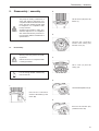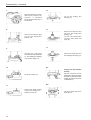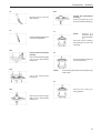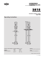
1
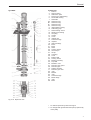
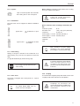
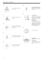
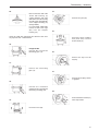
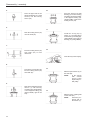
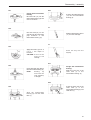
281S
Vertical sewage pump
Type B/M
Operating instructions
Herborner Pumpenfabrik J.H. Hoffmann GmbH & Co. KG
Address
Littau 3-5
D-35745 HERBORN
Phone
+49
(0) 2772
933 - 0
Telefax
+49
(0) 2772
933 - 100
Internet
http://www.herborner-pumpen.de
e-mail
[email protected]
Original operating instructions
A - V1 30 GB
Translation
Copyright
This operating instructions is to be translated into the
language of the user country for shipment into countries of
the European Economic Area.
Transmission or duplication of this document, usage and
communication of its content are prohibited if not expressly
authorized. Violations create liability for damages.
If inconsistencies should occur in the translation, please
consult the original operating instructions (German) for
clarification or contact the manufacturer.
All rights reserved.
Table of contents
Table of contents
1.
1.1
1.2
Certificates ................................................ 4
Declaration of conformity ............................. 4
Declaration of manufacturer
(for supply without drive unit) ....................... 5
2.
2.1
2.2
2.3
2.4
2.4.1
2.4.2
2.4.3
2.4.4
2.4.5
2.4.6
2.4.7
2.4.8
2.4.9
General ....................................................... 6
Explosion view ............................................. 6
Wear parts .................................................... 8
Usage according to intended purpose ........ 8
Specifications ............................................. 10
Type identification ...................................... 10
Impeller ....................................................... 11
Installations ................................................ 11
Shaft sealing ............................................... 11
Drive motor ................................................. 11
Coupling ..................................................... 11
Support of pump unit .................................. 12
Dimensions, weight, performance data ..... 12
General data ............................................... 12
3.
3.1
3.1.1
3.2
3.3
3.4
3.5
Safety ........................................................ 13
Notes / explanations .................................. 13
Machine identification ................................ 13
Integrated safety systems (Option) ............ 14
Interfaces on the pump .............................. 14
Safety instructions ...................................... 14
Responsibility of user ................................. 15
4.
4.1
4.2
4.3
General hazard notes .............................. 16
Hazards ...................................................... 16
Hazardous areas around the pump .......... 16
Assembling, operators and
maintenance personnel ............................. 16
Installation of spare and wear parts .......... 16
Shutdown procedures ................................ 17
4.4
4.5
5.
5.1
5.2
5.2.1
5.2.2
5.3
5.3.1
5.3.2
5.4
5.4.1
5.4.2
5.5
5.6
5.6.1
5.6.2
5.7
5.8
5.9
5.9.1
5.10
Installation ................................................ 18
Scope of supply .......................................... 18
Transit and packing .................................... 18
Delivery (also of spares and wear parts) .. 18
Intermediate storage .................................. 18
Transit to the installation site
(of the customer) ........................................ 18
Handling by a fork lift ................................. 19
Handling by crane ...................................... 19
Pump weights ............................................. 19
Pump weights, type B/BF ........................... 19
Pump weights, type M/MF ......................... 20
Installation and setup ................................. 20
Dimensions ................................................. 21
Installation lengths and dimensions
of type B/BF ................................................ 22
Installation lengths and dimensions
of type M/MF ............................................... 22
Power supply .............................................. 23
Motor protection ......................................... 23
Rotation sense control ............................... 24
Changing the rotation sense ..................... 24
Motor connection diagrams: ...................... 25
5.11
5.12
Routing of pipelines ................................... 25
Anti-freezing ............................................... 25
6.
6.1
6.2
Commissioning ........................................ 26
Operation modes and starting frequency .. 26
Starting ....................................................... 27
7.
7.1
7.2
7.5
7.6
7.7
Service / maintenance / cleaning ............ 28
Service ........................................................ 28
Maintenance instructions at prolonged
periods of standstill .................................... 29
Bearing lubrication ..................................... 29
Bearing lubrication of motor shaft ............. 30
Bearing lubrication of pump shaft ............. 30
Re-lubrication ............................................. 30
Re-lubrication of anti-friction bearings ...... 30
Re-lubrication of slide bearings ................. 30
Re-lubrication by grease pump
(available as an accessory only) ............... 30
Re-lubrication with lubricant dispenser
(available as an accessory only) ............... 32
Couplings ................................................... 32
Cleaning ..................................................... 33
Tightening torques for bolts ....................... 33
8.
Malfunction / cause / rectification ........... 34
9.
9.1
9.2
Disassembly / assembly ......................... 37
Disassembly ............................................... 37
Assembly .................................................... 43
7.3
7.3.1
7.3.2
7.4
7.4.1
7.4.2
7.4.3
7.4.4
Table of figures
Fig.
Fig.
Fig.
Fig.
Fig.
Fig.
Fig.
2-1a
2-1b
3-1
3-2
5-1
5-2a
5-2b
Explosion view ............................................. 6
Explosion view ............................................. 7
Nameplate .................................................. 13
Interfaces on the pump .............................. 14
Handling by crane ...................................... 19
Dimensions ................................................. 21
Dimensions ................................................. 21
Certificates
1.
Certificates
1.1
Declaration of conformity
EC-Declaration of conformity
in terms of
-
the EC Machinery Directive 98/37/EC, Appendix II A (Version 2002)
-
the EC Low Voltage Directive 73/23/EWG, Appendix III (Version 2002)
-
the EC directive EMC 89/336/EEC, Appendix I and II (Version 2002)
also with explosion-proof model:
-
the EU Directive Equipment and Protective Systems Intended for Use in Potentially Explosive Atmospheres 94/9/
EC (ATEX)
We hereby state that the model with the
Name:
Vertical sewage pump
Type:
281S
corresponds to the above regulations and the DIN EN standards listed below in the supplied model:
Directive /
Standard
Title
EC Machinery Directive
Version
Comments
1998
Version 06/
2004
98/37/EC
DIN EN ISO Safety of machinery Basic concepts;
12100-1
general principles for design;
Part 1: Basic terminology,
methodology
2004
DIN EN ISO Safety of machinery;
Basic concepts, general
12100-2
principles for design;
Part 2; Technical principles and
specifications
2004
DIN EN 809 Pumps and pump units for liquids
1998
DIN EN
1050
Safety of machinery- Principles
for risk assessment;
1997
Directive /
Standard
Title
Directive /
Standard
Title
Version
Comments
EC directive EMC
1989
Version 06/
2004
DIN EN
50081-1
Electromagnetic compatibility
(EMC);
1993
Harmonised
standards
DIN EN
50082-2
Electromagnetic compatibility;
Generic Immunity Standart;
Industrial environment
1994
Harmonised
standards
Version
Comments
89/336/EG
also with explosion-proof model:
Directive /
Standard
Title
1994
Harmonised
standards
EU Directive Equipment and
94/9/EG
Protective Systems Intended
(Atex 100a) for Use in Potentially Explosive
Atmospheres
Version 02/
2004
Harmonised
standards
EN 1127-1
Explosive atmospheresExplosion pevention and
protection - Part 1: Basic
concepts and methodology
1997
Harmonised
standards
2001
Harmonised
standards
Version
Comments
EC Machinery Directive
1973
Version 06/
2004
DIN EN
60204-1
Safety of machinery;
Electrical equipment of
machines;
Part 1: General requirements
1998
Harmonised
standards
DIN EN
62079
Preparation of instructions,
Structuring, content and
presentation
2001
Harmonised
standards
73/23/EG
EN 13463-1 Non-electrical equipment for
potentially explosive
atmospheres;
Part 1: Basic method and
requirements;
prEN
13463-5
Non-electrical equipment
indended for use in potentially
explosive atmospheres;
Part 5: Protection by
constructional savety
This statement becomes invalid with a non-coordinated change.
Herborn, June 28, 2004
...............................................................
Signature
(Management)
4
Certificates
1.2
Declaration of manufacturer (for supply without drive unit)
Declaration of manufacturer
in terms of
-
the EC Machinery Directive 98/37/EC, Appendix II B(Version 2002)
also with explosion-proof model:
-
the EU Directive Equipment and Protective Systems Intended for Use in Potentially Explosive Atmospheres 94/9/
EC (ATEX)
We hereby state that the model with the
Name:
Vertical sewage pump
Type:
281S
is delivered without a drive unit, for installation in a machine or for assembly with other machines to a machine. It is
prohibited to start the machine until it has been verified that the machine into which this pump will be integrated or to which
this pump will be assembled meets the provisions above and the DIN EN standards listed below.
also with explosion-proof model:
Directive /
Standard
Title
EG-Richtlinie Maschinen
Version
Comments
1998
Version 06/
2004
98/37/EG
DIN EN ISO Safety of machinery 12100-1
Basic concepts;
general principles for design;
Part 1: Basic terminology,
methodology
1991
DIN EN ISO
12100-2
1995
Safety of machinery Basic concepts, general
principles for design;
Part 2; Technical principles and
specifications
DIN EN 809 Pumps and pump units for liquids
DIN EN
1050
Safety of machinery- Principles
for risk assessment;
1998
1997
Harmonised
standards
Harmonised
standards
Directive /
Standard
Title
Version
Comments
EU Directive Equipment and
94/9/EG
Protective Systems Intended
(Atex 100a) for Use in Potentially Explosive
Atmospheres
1994
Version 02/
2004
EN 1127-1
Explosive atmospheresExplosion pevention and
protection - Part 1: Basic
concepts and methodology
1997
Harmonised
standards
2001
Harmonised
standards
EN 13463-1 Non-electrical equipment for
potentially explosive
atmospheres;
Part 1: Basic method and
requirements;
prEN
13463-5
Non-electrical equipment
indended for use in potentially
explosive atmospheres;
Part 5: Protection by
constructional savety
This statement becomes invalid with a non-coordinated change.
Herborn, June 28, 2004
...............................................................
Signature
(Management)
5
General
2.
General
2.1
Explosion view
Type B/BF
Components
1. Lantern
2. Spacer bush**
4. Lubrication point
5. Deep groove ball bearing
6. Thrust ball bearing
7. Shaft tube
8b. Shaft seal ring
8c. Shaft seal ring
8e. Shaft seal ring
9. Intermediate bearing
10. Lubricating pipe
11. Shaft wearing sleeve
12. Stuffing box bearing
13. Vent plug
14. Casing
15. Cover
16. Impeller nut
17. Screwed flange
18. Impeller
19. Gland packing*
20. Bush
21. Bush
22. Shaft
23. Flange
24. Locking sleeve
25. Bearing mounting
26. Grooved pin
27. Circlip
28. Coupling
29. Cover
31. Bottom shaft
33. Locking sleeve
34. Bearing mounting
35. Top shaft
92. Joint
93. Washer
94. Joint
98. Motor
Fig. 2-1a Explosion view
*
For DN100 replaced by shaft seal ring 8c
** For designs including grease lubrication pump
replaced by V-rope pulley
6
General
Type M/MF
Components
1. Lantern
2. Spacer bush**
4. Lubrication point
5. Deep groove ball bearing
6. Thrust ball bearing
7. Shaft tube
8a. Shaft seal ring
8b. Shaft seal ring
8c. Shaft seal ring
8e. Shaft seal ring
9. Intermediate bearing
10. Lubricating pipe
11. Shaft wearing sleeve
12. Stuffing box bearing
13. Vent plug
14. Casing
15. Cover
16. Impeller nut
17. Screwed flange
18. Impeller
19. Gland packing*
20. Bush
21. Bush
22. Shaft
24. Locking sleeve
26. Grooved pin
27. Circlip
28. Coupling
29. Cover
31. Bottom shaft
33. Locking sleeve
34. Bearing mounting
35. Top shaft
56. Manhole cover
57. Pressure pipe gland
59. Pressure pipe
70. Support housing
71. Pressure pipe seal
92. Joint
93. Washer
94. Joint
95. Screwed flange
96. Blank flange
97. Joint
98. Motor
Fig. 2-1b Explosion view
*
For DN100 replaced by shaft seal ring 8c
** For designs with grease lubrication pump replaced by
v-belt pulley
7
General
2.2
Wear parts
The specifications fort he selection of wear parts are based
on the first demand for a two-year operation, in accordance
with DIN 24 296.
Wear parts
No. of pumps
(if existing)
1
2
3
4
5
6-7 8-9 10-...
Impeller
1
1
1
1
2
2
2
20%
Cover
1
1
1
1
2
2
2
20%
Bushes
1
1
1
2
2
2
3
25%
Anti-friction bearing set
1
1
1
2
2
2
3
25%
Shaft seal ring set
1
1
1
2
2
2
3
25%
Gland packing
1
1
1
2
2
2
3
25%
Shaft wearing sleeve
1
1
1
2
2
2
3
25%
Shaft + accessories
1
1
1
1
2
2
2
20%
2.3
Every pump is exclusively designed
for a purpose as specified above. Any
other use exceeding the intended
purpose, or a modification of the
pump without a written agreement by
the manufacturer is considered as
non-conforming to the intended
purpose. The manufacturer will not be
responsible for any damages
resulting therefrom. The risk rests fully
on the operator.
The pump must not be operated
unless it is ensured that all safety
equipment are completely installed
and function properly, and that the
system into which the pump is
installed meets the provisions.
Usage according to intended purpose
The pumps of the series indicated on the front page are
suitable for the conveyance of:
Nominal diameter 40-80
Sewage – soil water – waste water (for the drainage of
heating cellars, boiler houses, heating centres, slaughter
houses, washing rooms, sculleries, laundries, gully pits,
etc.)
Not allowed is the use of the pumps
for conveying
• combustible or explosive fluids;
• fluids with abrasive constituents;
• chemical agents attacking the
pump material.
Nominal diameter 100
Faeces – sewage – ground water pits – dirty waste water
(particularly suited for removal of faeces from collective
lines and pits).
The media used for pump operation
according to its intended purpose,
and the hazards in connection with it
are subject to the sole responsibility
of the operator.
For the conveyance of aggressive
and/or abrasive media, bronze or
special steels will be available as
pump materials.
In areas subject to explosion
hazards, only pumps of explosionproof design (Ex) can be used,
meeting the proper specifications.
8
General
II 2G T1-T4
The use conforming to the intended
purpose
also
includes
the
maintenance of the prescribed
operation, maintenance and repair
specifications.
Temperature classes
Explosion-proof gas atmosphere
Equipment category
Equipment group
Ex-identification
The explosion-proof vertical pumps / pump components
(if supplied without drive units) meet the requirements of
electric facilities subject to explosion-hazard, according
to the Guideline 94/9/EC of the European Council, dated
23rd March 1994, for intended purpose use in explosionhazard areas of
Equipment Group II Categories 2.
By the temperature class T4, the
pumps also meet the requirements of
the temperature classes T1 to T3.
Conditions of Use for Zone I and Zone II.
The Ex-identification on the nameplate of the pump is
related only to the pump components and the coupling
provided by the manufacturer. The drive unit proper is
subject to separate consideration. If the motor and the pump
are of different identification, the lower specifications shall
apply to both.
Explosion-proof behaviour is ensured
only for the use conforming to its
intended purpose. The limits indicated
in the purchase order and/or on the
nameplate must not be exceeded, in
any case.
To maintain the explosion proof
behaviour of the pump, if supplied
without motor, the following conditions
shall be maintained for the motor:
The temperatures permitted on the
motor flange and motor shaft must be
higher than the temperatures
developed by the pump.
Pumps with an integrated motor and
ATEX Certification, made by
Herborner Pumpenfabrik, meet this
condition.
9
General
2.4
Specifications
2.4.1 Type identification
Example:
281SH/100-2SP-230-BF-925-EX-W1-S1
Design
S1
=
=
Standard
Special design of serial number
Materials
W0
=
mixed materials
W1
=
all castings of EN-GJL-250
W2
=
all castings except impeller of EN-GJL-250, Impeller of
G-CuSn 10
W3
=
all castings of G-CuSn 10
W4
=
all castings of 1.4408
W5
=
all castings of EN-GJS-400-15
W6
=
all castings of 1.4439
Permitted usage
EX
=
=
Standard
Explosion proof quality
Dimension “e”
Design
=
unsectioned version
=
sectioned version
B
=
for installation in open pits
M
=
for installation in tanks and shafts
F
Type
Impeller diameter
Impeller version (if deviating from standard)
Number of blades
Nominal diameter of pressure connection DN [mm]
Hydraulic variation
Pump type
10
General
Motor cooling is effected by heat transfer of the cooling
ribs to the ambient atmosphere.
2.4.2 Impeller
Open screened impeller with automatic
fibre cutting tool for safe conveyance.
Follow the coolant temperature
specified on the nameplate!
2.4.3 Installations
The type series can be supplied in different installation
types:
Type B / BF =
for installation in open
pits
Motor connection sizes according to DIN 42677 (IM
B5).
Protection system
IP 55
Revolution rate
1450 (1750) /rpm (Standard)
Frequency
50 (60) Hz
Power supply < 2.2 kW 230/400 (265/460) V
Power supply > 3.0 kW 400/690 (460) V
Insulation class
Type M / MF =
for installation in tanks
and shafts
VDE 0530
F
Type
V1
Max. deviation of power supply
permitted ±10%, for the explosionproof designs ±5% of the power rating.
2.4.4 Shaft sealing
Sealing of all types is effected on the media-side via a
gland packing (19), from DN 100 upward via shaft seal
rings.
For type M additionally by shaft seal rings (8a).
Dry-running of a pump will destroy the
shaft sealing!
If a pump is delivered ex works without
motor, the latter shall be set up
according to the design data of the
purchase order and the specifications
indicated.
2.4.6 Coupling
2.4.5 Drive motor
The pump is equipped with a three-phase a.c. squirrel
cage motor.
The exact motor data shall be
derived from the nameplate!
The manufacturer supplies pumps with elastic torsion claw
couplings with elastic elements of PUR-plastics.
Couplings for Ex-service are
specifically identified by the EX-stamp
and information referring to the
manufacturer.
11
General
2.4.7 Support of pump unit
On the drive side, the pump is supported by two anti-friction
bearings with a re-lubricating facility in the bearing
mounting (25.) / support housing (70.). In the split design
(BF/MF), there are 2 additional anti-friction bearings in the
bearing mounting (34.).
The shaft is supported in the stuffing box bearing (12.) and
intermediate bearing (9.) by lubricated slide bearings.
These are either grease-lubricated or media-lubricated,
depending on the conditions of use. The number of
intermediate bearings (9.) depends on the construction
length of the pump.
2.4.8 Dimensions, weight, performance data
The dimensions and installation sizes are shown in chapter
5.6 Dimensions and the weights in chapter 5.4 Pump
weights. The performance and connection data of each
pump type are included in the purchase order and the
nameplate data.
2.4.9 General data
Media temperature range for:
lower temperature limit:
0 °C
upper temperature limit: +100 °C
Ambient temperature range for:
lower temperature limit: -
5 °C
upper temperature limit: + 40 °C
Density and toughness of pumped media:
Density:
max. 1000 kg/m3
Kinematical viscosity:
max. 1 mm2/s (1 cST)
For media of deviating density or
toughness, make sure to observed
motor performance in the case of
hydraulic power change.
Acoustic Pressure Level:
The acoustic pressure level of the pump at cavitation-free
operation in the Range of Qopt. remains below the limits
specified in the EC-Guideline 98/37/EG for machinery.
12
Safety
3.
Safety
3.1
Notes / explanations
We recommend to paste the
accompanying type nameplate of the
pump into the operation manual or
into the switchgear, so that they are
available to you whenever you need
them.
Warnings
are included in a frame and marked by a
”STOP sign”.
Hazard notes
are included in a frame and highlighted
by a warning triangle.
The nameplate is affixed to the fan cover above the
switchbox or on the lantern (if supplied without drive unit).
Hints
are included in a frame and marked by a
”hand”.
For queries and ordering of spare
parts, make sure to indicate the pump
type and the purchase order number.
Follow any additional nameplates on
the motor.
Squeezing hazards
are included in a frame and identified by
the adjacent symbol.
Hazards due to electric power
are included in a frame and identified by
the adjacent symbol.
Hazards due to explosive atmosphere
are included in a frame and identified by
the adjacent symbol.
Biological hazard
Biological hazards may develop during
decomposition of organic products in
sewage waters.
Instructions to wear personal safety
outfit
Fig. 3-1
Nameplate
Are included in a frame and identified by
the adjacent symbol.
Legend to fig. 3.1
Burning hazard
e.g. on electric motors are identified by
the adjacent symbol.
3.1.1 Machine identification
The data in the operating manual are exclusively
applicable to the type of pump shown on the front page.
1. Purchase order no.
9. CE-mark
2. Type description
10. Nominal head
3. Item no.
11. Nominal flow rate[m3/h]
[m]
[min-1]
4. Frequency
[Hz] 12. Rpm
5. Power output
[kW] 13. Operation voltage
[V]
6. Protection class
14. Year of construction
7. Insulation class F
15. Ex-proof identification
(only for Ex-pumps)
8. Ex-mark (only for Expumps)
13
Safety
3.2
Integrated safety systems (Option)
3.3
Interfaces on the pump
The integrated safety systems shall be inspected at regular
intervals j = annually.
The inspection methods to be applied are:
S = visual inspection, F = functional checkout.
Thermal winding protection
If the pump is additionally protected by direct temperature
control of the winding, the motor will be stopped at
excessive heat-up.
Checkout
Interval
Method
j
S, F
Fig. 3-2
This operation manual is an integral
part of the machine and must be
available to the operators at any time.
The included safety precautions shall
be followed.
Interfaces on the pump
There are the following interfaces on the pump:
1. Inlet connector flange
2. Outlet connector flange
3. Electric connection (terminal box)
4. Re-lubricating unit
It is strictly forbidden to cheat any
safety equipment or to vary their
functioning.
3.4
Safety instructions
It is essential that the user instructs
his operators and maintenance
personnel:
- on the protection equipment of the
pump;
- and supervises them to follow the
safety provisions.
14
Safety
This operation manual shall be retained for future
reference. The frequency of inspections and supervision
measures shall be maintained. The operations described
in this manual are set up in such a manner that they are
3.5
Responsibility of user
In the European Economical Region,
the national adoption of the
Framework Guideline (89/391/EEC)
and the accompanying individual
guidelines, in particular the Guideline
(89/655/EEC) and the Minimum Probisions for Safety and Health
Protection for the Use of Working
Tools and Utilities by Working People,
in their applicable wording shall be
followed and maintained.
- understood in the operation manual
chapters handling and operation
modes by an operator;
- in the chapters transportation,
installation and setup, maintenance,
malfunction/cause/rectification by an
experienced engineer.
The chapters Transportation, Installation and setup,
Maintenance, Malfunction/cause/rectification are
provided for skilled engineers only. Operations described
in these chapters shall be performed by skilled engineers
only.
Trained person
The Working Safety Rules shall be
observed. g
The user shall strive to obtain the local operation permit
and follow the impositions connected to it. At the same
time, he shall meet the local provisions for
A person trained by a skilled engineer
to fulfil the functions assigned to him/
her and informed about the potential
hazards in the case of improper
behaviour an instructed, if required,
about the protective equipment and
safety provisions needed.
- the safety of personnel (Provisions for
the Prevention of Accidents)
- the safety of working tools (Protection
equipment and Maintenance)
- the disposal of products (waste law)
- the disposal of materials (waste law)
- cleaning (cleaning agents and their
disposal)
- the protection of environment.
Connections:
Trained engineer
A person who can judge the assigned
duties and potential hazard on the
basis of his/her technical education,
know-how and experience as well as
the relevant standards.
Before operating the pump, the user shall ensure that
during assembly and startup, if this is carried out by the
user himself, the local provisions (e.g. for electric supply)
are met.
In its definition similar to EN
60204-1.
15
General hazard notes
4.
General hazard notes
4.1
Hazards
The safety systems and safety provisions described in this
manual shall be use and followed., respectively. The pump
shall be operated on the control elements or from a remote
control system. Make sure to keep the access ways free
from objects when opening the pump, so that an
unobstructed access is possible at any time.
4.3
Assembling, operators and maintenance
personnel
The personnel required for assembly, operation and
maintenance includes persons who are responsible for
transportation, assembly, installation, operation,
preparation, and cleaning of the pump and for
troubleshooting.
1. The pump may be mounted and
operated by trained and authorize
persons only.
2. The responsibilities for operating the
pump must be clearly established and
followed, so as to avoid any
misunderstandings and doubtful
competences.
During preparation, maintenance and
repairs , make sure to avoid any
squeezing hazards!
3. For
all
activities
(operation,
maintenance, repair, etc.) the shutdown
procedures stated in the operation
manual shall be followed.
4.2
4. The operator shall abstain from any
handling mode that certainly would
deteriorate the safety of the pump.
Hazardous areas around the pump
5. The operator shall ensure that only
authorised persons are allowed to work
on the pump.
For preparatory, maintenance, repair
and cleaning activities, the area of
about 1 m around the pump shall be
regarded as a hazardous area. The
operating area is limited to the
operating controls.
6. The operator undertakes to report any
changes occurred on the pump that
would affect safety to the user
immediately.
7. The user undertakes to operate the
pump in an unobjectionable state only.
8. The user shall provide any protective
equipment needed meeting the legal
provisions and the requirements of the
media to be conveyed.
Make sure to install and/or fasten the
pump so that no persons can stay in
the direction of pumping
4.4
Installation of spare and wear parts
We expressly point out that any spares and wear parts not
delivered by us consequently are neither tested nor
released by us. The installation and/or the use of such
products may adversely affect the properties of your pump
in terms of design and performance.
The responsibility and liability of Herborner Pumpenfabrik
will be excluded for any damage caused by the use of
non-original components or non-original accessories.
16
General hazard notes
4.5
Shutdown procedures
It is essential that the following
shutdown procedure is maintained
prior to any maintenance, cleaning
and/or repair activities (by skilled
personnel only).
Disconnect the pump from power supply
- Turn the power switch on the power
supply cabinet to ”0”.
- Make sure that no voltage is applied.
- Secure the power switch against
inadvertent re-starting by a padlock
Close the open electric cabinets
during cleaning, to avoid any ingress
of water or dust. If not observed
carefully, hazards will occur for the life
and health of your operators!
17
Installation
5.
Installation
Packing for road traffic by lorry
5.1
Scope of supply
For transport by road traffic, the pump is packed and
fastened to a transit pallet.
The detailed scope of supply is
revealed in the order confirmation.
5.2.2 Intermediate storage
On arrival, the freight packing of the pump and spare parts
are laid out for approx. 3 months.
Storage conditions
The counter flange with thread ”G” according to the nominal width, is part of the supply for type B.
Suitable motor sizes depending on lantern:
Closed and dry room with an ambient temperature of 5 40 °C.
5.3
Transit to the installation site (of the customer)
80 L, 90 S, 90 L, 100 L, 112 M, 132 S, 132 M, 160 M, 160 L
Motor connection sizes acc. to DIN 42677 (IM B5).
5.2
Transit and packing
Transit shall be performed by skilled
personnel under local conditions
only.
The pumps from Herborner Pumpenfabrik are carefully
checked and packed prior to shipment, but no damage
can be excluded during transit.
5.2.1 Delivery (also of spares and wear parts)
Receiving inspection
Check for complete delivery by comparison with the
delivery note!
The pump is transferred on the transit
pallet right to the installation site of
the customer.
For damages
Check the supply for damages (visual inspection)!
For complaints
If the delivery has been damaged during transit:
- Immediately make contact with the last
forwarder!
- Keep the packing as an evidence (for
a possible review by the forwarding
agent or for return shipment).
Packing for return shipment
If possible make use of the original packing container and
the original packing material. If both is no more available:
- If available, request a packing
company with expert personnel. Place
the pump on a pallet (must be
designed according to weight).
- Any queries arising to packing and
transport security should be referred
to Herborner Pumpentechnik.
18
Hoisting gear and sling belts must be
of sufficient dimension for the total
pump weight (see chapter 5.4 Pump
weights). If necessary, secure the
pump during transit by appropriate
sling gear, because there might exist
a hazard of tilting, especially for topheavy objects. The pump shall be
placed on a horizontal surface of
sufficient firmness in all directions.
Installation
5.3.1 Handling by a fork lift
- The fork lift must be designed in
conformity with the weight of the pump.
5.4
5.4.1 Pump weights, type B/BF
- The driver shall have a proper driving
license for moving loads by fork lift.
5.3.2 Handling by crane
Type BF
- Fasten the pump to the crane by means
of appropriate sling gear (e.g.
crossbeam,
belt,
multi-point
suspensions, ropes, etc.) at the lifting
points and move it.
Type B
- The crane must be designed for
handling weights of the pump.
- The operator must be authorized to
operate a crane.
Pump weights
dimension ”e”
[mm]
525
725
925
1025
1225
1450
1550
1650
1750
1850
1950
2050
2150
2250
2375
2450
2575
2675
2625
2825
3025
3125
3325
3550
3650
3750
3850
3950
4050
4150
4250
40
[kg]
47
50
53
54
57
63
65
66
68
69
71
72
73
75
79
78
82
84
100
103
105
107
110
116
117
119
120
122
123
124
126
50
[kg]
71
73
76
78
81
87
88
90
91
92
94
95
97
98
103
101
106
107
123
126
129
130
133
139
141
142
143
145
146
148
149
H65
[kg]
75
78
81
83
85
92
93
94
96
97
99
100
102
103
108
106
111
112
128
131
134
135
138
144
146
147
148
150
151
153
154
281S...
65
[kg]
169
174
179
181
185
197
200
202
204
206
209
211
213
216
225
220
229
232
253
257
262
264
269
280
283
285
287
289
292
294
296
80
[kg]
119
123
128
130
135
146
149
151
153
156
158
160
162
165
174
169
179
181
202
206
211
213
218
229
232
234
236
239
241
243
245
H100
[kg]
101
106
111
113
117
129
131
134
136
138
141
143
145
147
157
152
161
164
184
189
194
196
200
212
214
217
219
221
224
226
228
100
[kg]
157
162
167
169
174
187
189
192
194
197
199
202
204
207
217
211
222
224
244
249
253
256
261
273
276
278
281
283
286
288
291
For designs with flanges, the total
weights of the types 40, 50 and H65
are increased by 11 kg, for the Types
65, 80, H100 and 100 by 26 kg.
Fig. 5-1
Handling by crane
The total weights may vary by largersized motors and different producers.
19
Installation
The following aspects shall be maintained for installation:
Type MF
Type M
5.4.2 Pump weights, type M/MF
dimension ”e”
[mm]
525
725
925
1025
1225
1450
1550
1650
1750
1850
1950
2050
2150
2250
2375
2450
2575
2675
2625
2825
3025
3125
3325
3550
3650
3750
3850
3950
4050
4150
4250
40
[kg]
87
91
95
96
100
107
109
111
112
114
116
118
120
121
126
125
130
132
148
151
155
157
160
165
167
169
170
172
174
176
178
50
[kg]
112
116
119
121
125
132
133
135
137
139
141
142
144
146
151
150
155
157
172
176
179
181
185
190
191
193
195
197
199
200
202
281S...
H65
65
[kg] [kg]
117
215
121
221
125
227
126
230
130
236
137
249
139
252
141
255
142
258
144
261
146
264
148
267
150
270
151
273
156
283
155
279
160
289
162
292
178
312
181
318
185
324
187
327
190
333
195
343
197
346
199
349
200
352
202
355
204
358
206
361
208
364
- The pump assembly shall be firmly
mounted for permanent stability.
80
[kg]
164
170
176
179
185
198
201
204
207
210
213
216
219
222
232
228
238
241
261
267
273
276
282
292
295
298
301
304
307
310
313
H100
[kg]
155
162
169
173
180
194
198
201
205
208
212
215
219
222
233
229
240
244
264
271
278
282
289
300
303
307
310
314
318
321
324
100
[kg]
219
226
234
237
245
260
264
268
271
275
279
282
286
290
301
297
309
313
332
339
346
350
357
369
373
376
380
384
387
391
395
The total weights may vary by largersized motors and different producers.
5.5
Installation and setup
The connecting flanges must be properly aligned and be
fastened by screws so that no leakages occur. The seals
must be resistant against the operating medium.
Pumps in split design BF/MF shall be
finally pre-mounted prior to
installation according to chapter 9.2
Assembly (from Fig. 51).
20
- The pump shall not be subject to
mechanical stress when tightening the
mounting screws.
- The deviation of the pump centreline
from the vertical shall not exceed 2°.
- The pump cover (15) shall be relieved
from the total weight by additional
fastening means (flange or manhole
cover).
- The assembly components (e.g.
lubricating pipe) must not be damaged.
- The motor and the upper bearing
support shall be flood-safe.
Sufficient space shall be provided for
maintenance and repair!
For the installation of the pump, follow
the safety provisions for working in
closed rooms in sewage disposal
facilities, as well as the generally
approved ”Rules of the Art”.
Installation
5.6
Dimensions
Type B/BF
Type M/MF
Flange connector dimensions of the pressure pipe acc. to
DIN 2501, PN 10.
Flange connector dimensions of the pump casing acc. to
DIN 2501, PN 6.
Fig. 5-2a Dimensions
Fig. 5-2b Dimensions
21
Installation
5.6.1 Installation lengths and dimensions of type B/BF
Sizes of the pump and flange
DN
Motor types, lanterns, couplings
DN
40
50
H65
65
80
H100
100
a
355
355
355
490
490
490
490
b
310
310
310
425
425
425
425
c
143
149
158
178
192
240
252
300
Ø d
15
15
15
18
18
18
18
Ø g
75
75
75
110
110
110
110
40, 50, H65
Lanterns
LF 11/1
Ø F
LF 11/2
200
Motor types
LF 11/4
250
80 L
90 S
100 L
112 M
132 S
132 M
28
38
38
156
166
201
m
325
365
400
440
450
470
525
50
60
80
p
110
140
140
170
165
160
200
q
210
270
260
320
310
290
365
Ø r
140
140
140
185
185
185
185
t
45
45
45
65
65
65
65
u
200
200
200
290
290
290
290
Ø k max.
h
i max.
DN
65, 80, H100, 100
Lanterns
LF 12/1 LF 12/2
LF 12/4
LF 12/5
Ø F
200
250
300
350
Motor types
90 S
90 L
100 L
112 M
132 S
132 M
160 M
160 L
Ø k max.
h
i max.
28
38
38
45
162
172
207
250
50
60
80
110
j
23
23
23
33
33
33
33
l
150
150
150
220
220
220
220
w
160
160
185
200
200
220
240
y
105
105
105
120
120
120
120
z
97
99
120
114
136
152
152
5.6.2 Installation lengths and dimensions of type M/MF
Motor types, lanterns, couplings
DN
Installation lengths “x“
Type BF (sectioned version)
Type B (unsectioned version)
DN
22
Maß
40
50
H65
65
80
H100
100
“e“
515
715
915
1015
1215
1440
1540
1640
1740
1840
1940
2040
2140
2240
2365
2440
2565
2665
515
715
915
1015
1215
1440
1540
1640
1740
1840
1940
2040
2140
2240
2365
2440
2565
2665
525
725
925
1025
1225
1450
1550
1650
1750
1850
1950
2050
2150
2250
2375
2450
2575
2675
530
730
930
1030
1230
1455
1555
1655
1755
1855
1955
2055
2155
2255
2380
2455
2580
2680
545
745
945
1045
1245
1470
1570
1670
1770
1870
1970
2070
2170
2270
2395
2470
2595
2695
595
795
995
1095
1295
1520
1620
1720
1820
1920
2020
2120
2220
2320
2445
2520
2645
2745
605
805
1005
1105
1305
1530
1630
1730
1830
1930
2030
2130
2230
2330
2455
2530
2655
2755
525
725
925
1025
1225
1450
1550
1650
1750
1850
1950
2050
2150
2250
2375
2450
2575
2675
2615
2815
3015
3115
3315
3540
3640
3740
3840
3940
4040
4140
4240
2615
2815
3015
3115
3315
3540
3640
3740
3840
3940
4040
4140
4240
2625
2825
3025
3125
3325
3550
3650
3750
3850
3950
4050
4150
4250
2630
2830
3030
3130
3330
3555
3655
3755
3855
3955
4055
4155
4255
2645
2845
3045
3145
3345
3570
3670
3770
3870
3970
4070
4170
4270
2695
2895
3095
3195
3395
3620
3720
3820
3920
4020
4120
4220
4320
2705
2905
3105
3205
3405
3630
3730
3830
3930
4030
4130
4230
4330
2625
2825
3025
3125
3325
3550
3650
3750
3850
3950
4050
4150
4250
Lanterns
40, 50, H65
LF 11/1
LF 11/2
Ø F
200
250
300
Motor types
80 L
90 S
100 L
112 M
132 S
132 M
Ø k max.
h
i max.
28
38
38
206
216
251
50
60
80
DN
Lanterns
LF 11/4
65, 80, H100, 100
LF 12/1 LF 12/2
LF 12/4
LF 12/5
Ø F
200
250
300
350
Motor types
90 S
90 L
100 L
112 M
132 S
132 M
160 M
160 L
Ø k max.
h
i max.
28
38
38
45
212
222
257
300
50
60
80
110
Installation
Installation lengths “x“
Grounding, zero connection, currentoperated earth leakage protection,
etc. must meet the provisions of the
local power supplier and function
properly, as checked by the skilled
electrician.
40
50
H65
65
80
H100
100
“e“
Type M (unsectioned version)
Maß
655
855
1055
1155
1355
1580
1680
1780
1880
1980
2080
2180
2280
2380
2505
2580
2705
2805
660
860
1060
1160
1360
1585
1685
1785
1885
1985
2085
2185
2285
2385
2510
2585
2710
2810
670
870
1070
1170
1370
1595
1695
1795
1895
1995
2095
2195
2295
2395
2520
2595
2720
2820
690
890
1090
1190
1390
1615
1715
1815
1915
2015
2115
2215
2315
2415
2540
2615
2740
2840
705
905
1105
1205
1405
1630
1730
1830
1930
2030
2130
2230
2330
2430
2555
2630
2755
2855
755
955
1155
1255
1455
1680
1780
1880
1980
2080
2180
2280
2380
2480
2605
2680
2805
2905
765
965
1165
1265
1465
1690
1790
1890
1990
2090
2190
2290
2390
2490
2615
2690
2815
2915
525
725
925
1025
1225
1450
1550
1650
1750
1850
1950
2050
2150
2250
2375
2450
2575
2675
Type MF (sectioned version)
DN
2755
2955
3155
3255
3455
3680
3780
3880
3980
4080
4180
4280
4380
2760
2960
3160
3260
3460
3685
3785
3885
3985
4085
4185
4285
4385
2770
2970
3170
3270
3470
3695
3795
3895
3995
4095
4195
4295
4395
2790
2990
3190
3290
3490
3715
3815
3915
4015
4115
4215
4315
4415
2805
3005
3205
3305
3505
3730
3830
3930
4030
4130
4230
4330
4430
2855
3055
3255
3355
3555
3780
3880
3980
4080
4180
4280
4380
4480
2865
3065
3265
3365
3565
3790
3890
3990
4090
4190
4290
4390
4490
2625
2825
3025
3125
3325
3550
3650
3750
3850
3950
4050
4150
4250
80
H100
The section and voltage drop of the
power supply line shall meet the relevant requirements. The voltage
indicated on the nameplate of the
pump shall meet the existing power
supply voltage.
The connection of a potential
equalisation shall be provided
between the pump and foundation
ground.
Sizes of the pump and flange
DN
40
50
H65
65
100
a
560
560
560
560
560
560
630
b
530
530
530
530
530
530
600
5.8
c
143
149
158
178
192
240
252
d
500
500
500
500
500
500
570
f
106
106
106
106
106
106
120
A motor protection switch or an adequate protector with a
tripping characteristic according to DIN VDE 0660 shall be
used.
Motor protection
øg
75
75
75
110
110
110
110
m
325
365
400
440
450
470
525
ør
140
140
140
185
185
185
185
w
160
160
185
200
200
220
240
Direct start:
z
97
99
120
114
136
152
152
At direct start, the motor protection
switch shall be regulated for nominal
motor current.
5.7
Power supply
The power connection must be
performed by a skilled electrician
only.
23
Installation
Star-delta start:
The motor protection switch shall be
included in the delta circuit and
adjusted to 0.58 times the nominal
power maximum.
Motors with additionally installed
PTC-resistor sensors:
- Test voltage of PTC-sensors 1.5 V
max.!
- To be operated with a tripping aid
only!
The pump shall be stopped
immediately after starting.
Dry-running of the pump will
destroy the shaft sealing.
By rotation sense control, the pump
shall be safeguarded so that no
personal injury can happen by a
rotating impeller. Avoid gripping into
the pressure pipe joint or the suction
opening of the pump casing.
EX:
If the thermal winding protector
optionally installed performs the
tripping, the system must not start
again automatically unless the
malfunction is checked and corrected
again.
5.9
Rotation sense control
Three-phase current motor shall be subject to a thorough
rotation sense control, at first start-up and when re-started
on a new installation site. Rotation in the wrong direction
means less pumping output and may damage the pump.
When viewed on the motor fan, the
latter shall rotate clockwise.
Rotation
sense
conforming to the rotation
arrow!
24
At a control system with several
pumps, each pump shall be tested
individually.
If an explosion hazard exists also
during installation, the rotation sense
must in no case be checked by
momentary starting the empty pump.
5.9.1 Changing the rotation sense
At incorrect rotation sense, the direct shall be reversed by
commuting two phases of the lead cable in the control
system.
Installation
5.10
Motor connection diagrams:
The following rules are specifically
required for the application range of
DIN 1986:
Motor voltage (motor nameplate)
Operating Operating
voltage frequency
The pressure line shall be routed with
a back-pressure loop (180° arc)
through the backflow level and then
with slope into the collective line or
sewer.
Do not connect the pressure line to a
down-pipe.
No other pressure supplies shall be
connected to the pressure line.
Make sure to install a ….
shutoff gate valve for closing the
lines immediately in front of the pump,
to remove the pump without draining
the lines first.
Backflow preventer between the
pressure pipe joint and the shutoff
valve, to prevent the return flow of the
pumped medium and fluid bounces
after shutting down the pump.
Incorrect electric circuit type lead to
failure of the electric motor!g
5.12
5.11
Anti-freezing
Routing of pipelines
For the routing of the pressure line, the currently valid
specifications and the relevant regulations for the
prevention of accidents shall be followed.
In the case of freezing hazard or prior
to longer periods of standstill, make
sure to run the pump empty.
For laying the pipes, suitable
measures shall be taken to ensure
complete ventilation.
The pressure line shall be routed free
from freezing.
The pressure lines shall be supported
and connected free from stress. No
piping forces and moments shall act
on the pump.
25
Commissioning
6.
Commissioning
Before starting up the pump, inspect the pump and perform a functional checkout. Make sure to observe the
following items:
6.1
Operation modes and starting frequency
All types are designed for the S1 mode (permanent
operation) with an immersed casing component.
· Avoid the pump running dry!
· Has the electric connection be made in
compliance with local provisions?
· Is the temperature protector connected?
· Is the motor protector switch correctly
set?
A motor protection switch or an
adequate motor protector shall be
used, having a tripping characteristic
according to DIN VDE 0660.
· Is the rotation sense of the pump correct,
also if operated by an emergency
power supply?
· Does the level control operate correctly?
· Are the gate valves needed for
operation open?
· Are the connection and control cables
installed correctly?
· Is the pump mounted firmly?
Level controls must be installed so
that explosion-proof pumps are
permanently immersed with their
casing.
· Has the shaft been cleaned?
· Re the inlets and outlets of the pumping
station checked and free from any
hazard?
· Is for explosion-proof pumps the casing
permanently immersed in the medium?
Prolonged operation against closed
valves is not permitted, to avoid the
pumped medium and the pump being
heated up.
Coupled machines must be grounded
to exclude electric sparking.
To avoid severe temperature rise in the motor and
overloading of the pump, coupling, motor, seals and
bearings, 10 starting procedures per hour shall not be
exceeded.
Any lubricators additionally installed
need a start-up period of approx. 5 to
7 days, at a room temperature of about
20°C.
26
Commissioning
The switching frequency permitted for
any starting equipment shall be
requested from the producer
concerned.
6.2
Starting
· Open gate valves and shutoff cocks.
· Start the motor..
· Open the shutoff cocks of pressure
gauges.
First turn the gate valve open slightly on empty pressure
line., then at full power until reaching the motor capacity
permitted (compare ammeter reading with respective data
on the motor nameplate!).
27
Service / maintenance / cleaning
7.
Service / maintenance / cleaning
The chapter Service / maintenance /
cleaning is intended for skilled
personnel. Maintenance, repair and
cleaning activities must be performed
by skilled engineers only. The skilled
personnel shall be provided with
personal protective wear (e.g.
protective gloves).
During operation the pump is subject to vibrations that
may cause fastening screws or clamps to work loose. To
prevent damage, make sure to inspect the pump for loose
connections, at regular intervals (recommend interval for
one-shift operation: 6 months). Regularly remove any dust
accumulations and dirtiness.
Before performing any maintenance,
repair and cleaning operations, make
sure to follow the shutdown procedure
(see chapter 4.5 Shutdown
procedures). Make sure to only tools
and objects specifically intended for
these operations.
Skilled engineer:
Any person who, based on his/her technical education,
know-how and experiences as well as the knowledge of
the relevant standards is capable of judging the duties
assigned to him/her and who can recognize any potential
hazards.
Definition is similar to EN 60204-1.
When installing the pump, make sure
to follow the safety precautions for
work in closed rooms of sewage
disposal systems and the generally
approved ”Rules of the Art”.
The content and setup of this
maintenance instruction has been
based on DIN 31 052 ”Troubleshooting”.
To ensure smooth operation of the pump free from troubles,
it is necessary that the pump is cleaned and maintained at
regular intervals.
Give the impeller time to decelerate
until standstill, otherwise there will be
a hazard of injury. Make sure that the
pump cannot roll away or trip over.
There will be a danger of injury of
damage!
Make always sure to wear personnel
protective clothing like safety glasses
and rubber gloves, when pumping
matter harmful to your health.
28
7.1
Service
The hoisting gear must be of sufficient
capacity and dimensions fort he total
weight of the pump. Make sure to
follow the provisions for the
prevention of accidents and the
general rules of technology.
Subject the joisting gear to a visual
inspection for wear and corrosion, at
half-yearly intervals, and replace it as
necessary.
During maintenance and repairs, be
sure to prevent squeezing hazards!
Service / maintenance / cleaning
During maintenance, observe the
hazards by electric power!
Waste and emissions shall be
collected in suitable containers and
disposed of as legally specified.
7.2
Interventions in explosion-proof
pumps must be performed in/by
workshops/persons authorized to do
so, using only original components
produced by the manufacturer.
Otherwise, the Ex-Certificate will
expire.
Maintenance instructions at prolonged periods
of standstill
In regular cases, the pumps do not need any maintenance.
However, to prevent the pump from blocking, rotate the
motor shaft several times at half-yearly intervals by hand.
The anti-friction bearings of the motor are free from
maintenance.
The pumps must be protected against
weather effects (UV-radiation,
sunlight, high air humidity, frost, etc.).
Prior to removal of the pump in areas
subject to explosion hazard, make
sure to ventilate the shaft or building
sufficiently, since otherwise there
might be a danger of explosion by
spark ignition.
·
Prior to installation of the sewage pump
Before connection to electrical power rotate
the motor shaft several times by hand.
Dry-running of Ex-pumps used in
areas subject to explosion hazard is
not permitted.
Repairs and extensive maintenance
work of pumps in explosion-proof
design shall be performed on unmounted units in separate rooms.
7.3
Bearing lubrication
The bearing temperature (pump and motor) may be max.
50 °C higher than room temperature, but not exceed +90°C.
Place the pump on a firm base and
secure against tipping over!
Danger of tipping exists when
disconnecting the pump from the
piping system.
Ball bearings at a revolution rate of
1450 (1750) rpm shall be re-lubricated
after 20.000 operating hours, at a rate
of 2900 (3600) rpm after 10.000
operating hours, but not later than
after 3 years, or replaced as
necessary.
29
Service / maintenance / cleaning
Make sure to use only physiologically
safe oil and greases for applications
in used or raw waters.
Ball bearings used in Ex-areas at a
revolution rate of 1450 (1750) rpm
shall be replaced at intervals of 20.000
and such of 2900 (3600) rpm at
intervals of 10.000 operating hours.
7.4.1 Re-lubrication of anti-friction bearings
7.3.1 Bearing lubrication of motor shaft
Anti-friction bearings are re-lubricated on
tapered grease nipples H1, G¼ (DIN
71412).
Permanently lubricated and maintenance-free anti-friction
bearings for the motor shaft of all pumps.
7.3.2 Bearing lubrication of pump shaft
DN 40/50/H65:
Anti-friction bearings are prelubricated ex-works.
7.4
Re-lubrication
At a revolution rate of 1450 (1750) rpm
re-lubricate at intervals of 5000 and at
a revolution rate of 2900 (3600) rpm at
intervals of 2500 operating hours with
7 g of grease.
DN 65/80/H100: At a revolution rate of 1450 (1750) rpm
re-lubricate at intervals of 4000 and at
a revolution rate of 2900 (3600) rpm at
intervals of 2000 operating hours with
8 g of grease.
DN 100:
Make sure to use the same grade of
lubricant or re-lubricate anew. Use
water-resistant grease.
At a revolution rate of 1450 (1750) rpm
re-lubricate at intervals of 3500 and at
a revolution rate of 2900 (3600) rpm at
intervals of 2000 operating hours with
10 g of grease.
7.4.2 Re-lubrication of slide bearings
Make sure to avoid over-lubricating
the bearings.
Slide bearings are re-lubricated on flat
grease nipples M1, G¼ (DIN 3404).
By hand
Lubrication grease is harmful to your
health if swallowed.
At a revolution rate of 1450 (1750) rpm 1 x and at a
revolution rate of 2900 (3600) rpm apply 10 g of grease 2
x per week.
7.4.3 Re-lubrication by grease pump (available as an
accessory only)
Grease shall be disposed of properly!
30
If lubrication is ex-works by automatic grease pump, the
slide bearings on the pump will be re-lubricated
automatically during operation by a grease pump. For this
purpose, the grease is pumped automatically from the tank
through the lubricant lines to each lubrication point.
Service / maintenance / cleaning
The pumped quantity shall be
regulated during operation of the
pump.
Ex-works the grease pump is set to
full stroke.
Re-fill grease in time, before air is
pumped into the lubrication lines.
Re-fill the grease tank only after
release of the motor in accordance
with the 5 safety rules of electrical
engineering.
For regulating the grease volume needed:
- Loosen the counter-nut of the adjusting
bolt at the grease pump.
- Turn the adjusting bolt gently clockwise
to its stop.
- Turn the adjusting bolt approx. ½ turn
counter clockwise (corresponds to 1/8
of the full stroke volume = approx. 1 g
of grease per hour).
Grease filling of the grease pump and the lubricant lines:
-
Actuate the drive shaft of the grease
pump until the grease leaves all outlet
boreholes without any air bubbles.
-
Connect cleaned lubricant pipes.
-
Re-start the grease pump until all
lubricating lines are filled and the
grease emerges at the end free from
bubbles.
-
Tighten the lubricant lines at each
lubrication point.
- Re-tighten the counter-nut
Do not tighten the counter-nut by force.
Only use greases of the NLGI Class 2
according to DIN 51818.
After loosening the counter-nut, gently turn the adjusting
bolts at connections not needed clockwise until they stop.
Do not plug the outlet boreholes of
connections no longer needed by
blind screws or blind rivets.
Use wooden or cork plugs instead.
Do not mix different grease types.
Perform thorough cleaning of the grease pump including
lubricant lines using petrol or kerosene:
-
at least once per year;
-
when re-starting the pump after a
prolonged period of delivery;
-
after several months of standstill.
Now the grease pump shall be filled with grease again.
31
Service / maintenance / cleaning
7.4.4 Re-lubrication with lubricant dispenser (available
as an accessory only)
Only greases of the NLGI Class 2
according to DIN 51818 shall be used
On ex-works delivery with an automatic lubricant dispenser,
the slide bearing on the pump will be re-lubricated
automatically. For this purpose, the lubricant dispenser
permanently presses the grease with a constant pressure
of 4 bar max. through the lubricant lines to each lubrication
point.
Make sure to mix greases only with
lithium complex soap or barium
complex soap as thickening agent.
Ambient temperature:
lower temperature limit:
0 °C
upper temperature limit: + 40 °C
The lubricant dispenser needs a
start-up preparation time of approx. 5
to 7 days at a room temperature of
about 20°C.
The lubricant dispenser dispenses a grease volume of
approx. 5 g per week. This results in a dispensing duration
of 6 months.
The consumption of lubricant shall be
checked on the filling level indicator
at regular intervals.
The lubricant dispenser remains at
pressure even some days after use.
Do not open the lubricant dispenser.
Do not unscrew the lubricant
dispenser during the dispensing
duration.
7.5
Replacement of the lubricant
dispenser only after release of the
motor according to the 5 safety rules
of electrical engineering.
Couplings
Works on the coupling shall be
performed at standstill only. The drive
unit must be secured against
accidental start-up.
Replacement of lubricant dispenser:
- Unscrew the used-up lubricant
dispenser.
- Keep the lubricant dispenser vertical.
- Screw-in the red activation screw until
the annular lub tears off at the
predetermined breaking point.
- Unscrew the plug.
- Turn the lubricant dispenser by hand
onto the lubrication point.
32
Any protection equipment shall be
installed as required after any
maintenance work.
Service / maintenance / cleaning
7.6
The torsion backlash control must
take place, for the first time, after 3000
operating hours, but not later than
after 4 months. If only a small wear is
found by this control, the control can
be done after 6000 hours or 1 year
later. At high wear, the installation
conditions of the coupling and the
operating conditions of the pump
shall revised. For this purpose, we
recommend to make contact with
Herborner Pumpenfabrik.
To check the torsion backlash, one coupling part is rotated
to the stop, without any torque, and a marking is applied to
both coupling halves. By another rotation of the coupling
half into the opposition direction until it stops, the distance
is determined (max. distance approx. 8 mm).
The coupling provided ex-works permits emergency
operation to be run after the elements have worn. This
causes direct contact between the metal parts, leading to
damage.
Emergency operation is not permitted
in Ex-areas.
Cleaning
When removing or disassembling the pump, clean it from
any deposits, if necessary by mechanical means, to ensure
smooth operation.
In case the pump is to be shut down and taken out of
service for a prolonged working period, it shall first be
thoroughly flushed with clean water and cleaned carefully.
Any dirt residues dried-in, lime deposits, etc. may obstruct
the impeller and the shaft.
7.7
Tightening torques for bolts
thread
stainless
not stainless
(A4)
8.8
10.9
[Nm]
[Nm]
[Nm]
M8
18,5
23,0
32,0
M10
37,0
46,0
64,0
M12
57,0
80,0
110,0
M16
135,0
195,0
275,0
M20
230,0
385,0
540,0
All bolts and screws shall be
tightened properly during mounting.
On the coupling, the threaded pins for
securing the hub shall be
safeguarded additionally against
working loose, e.g. by pasting with
Loctite (medium-hard).
33
Malfunction / cause / rectification
8.
Malfunction / cause / rectification
Malfunction
Pump does not
work! Danger of
dry-running!
Cause
Rectification
Pump or pipeline Ventilate or fill
not filled
pump and
completely
pressure line
Feed line and/or Clean feed.
impeller clogged Remove any
deposits in the
pump/piping
The facts and remarks to
”troubleshooting, reason, correction”
are in such wording that any persons
with technical education (see the
definition in chapter 3.4 ”Safety
instructions”) in
- Electricity / electronics
- Mechanics / service
are able to follow them.
Motor does not
rotate
Check electric
installation
Gate valve
closed
Open gate valve
Pumping head
too high
Check system for
contamination or
check pump
layout
Density of
Dilute pumped
pumped medium medium or
too high
modify process
This personnel shall be equipped with
adequate tools and testing utilities.
Prior to any maintenance and repair
activities, make sure to follow the
shutdown procedures (see chapter 4.5).
If the instructions provided to not yield
success you should make contact
with Herborner Pumpenfabrik.
No malfunctioning will be expected
when following the operational
provisions with responsibility. The
pump shall not be removed before all
other measures have proved to be
without success. If any troubles
cannot be eliminated, we recommend
to contact our customer service.
34
Pump delivers
not enough.
Too high content Clarification
required
of air/gas in
pumped medium
Incorrect rotation Verify rotation
sense of pump
and exchange
two phase of
motor supply, if
necessary
Impeller loose or Check impeller
worn-out
and replace if
necessary
Pump works
against too high
pressure
Check pressure.
Change routing
of pipe. Verify
pump design
Gate valve
closed too much
Open gate valve
Piping or pump
clogged
Check piping or
pump, clean if
necessary
Running on 2
phases
Replace
defective fuse or
check connectors
Malfunction / cause / rectification
Malfunction
Cause
Rectification
Pump vibrates or Too high content Clarification
makes noise
of air/gas in
necessary
pumped medium
Malfunction
Pump starts but
stops
immediately
Incorrect rotation Check rotation
sense of pump
sense and
exchange two
phases to the
motor, if
necessary
Impeller loose or Check impeller
worn-out
and replace, if
necessary
Pump starts but
stops
immediately
Cause
Rectification
Pump does not
operate in the
operation range
specified
Verify operation
conditions
Clogged pump
has tripped
motor protection
relay
Check pump for
smooth running
Float switch not
adjusted
correctly
Check float
switch
Pump switches
over too often
Observe
operation mode
Motor incorrectly
connected
Connect motor
for existing
operating
voltage
Bearing runs
without
lubrication:
Refill grease,
replace bearings
if necessary
Pump does not
operate in
specified
operation range
Check operation
conditions
Anti-friction
bearing of motor
defective
Replace antifriction bearing.
Anti-friction
bearing of pump
not lubricated
properly
Clean and relubricate antifriction bearing
Anti-friction
bearing of pump
defective
Replace antifriction bearing
b) air bubbles in
lubricant pipes (if
existing)
Pump installed
under tension
Connector piping
must be routed
without tension
Cavitation
Check the
suction side for
clogging. Check
operating point,
adjust if
necessary
Too much grease
in bearing (only
for anti-friction
bearings of
pump)
Remove any
excessive grease
until balls are
just covered by
grease
Pump installed
under tension
Connection lines
must be routed
free of tension
Anti-friction
bearing defectiv
Replace antifriction bearing
Thermal switch
has tripped.
Verify motor
cooling
Insufficient
cooling of motor
Thermal switch
has tripped.
Check rotation
sense
Incorrect rotation
sense of pump
Power
consumption too
high
Check the pump
for smooth
functioning
Bearing runs hot
a) grease is
missing
Electric motor
runs excessively
hot
Incorrect rotation Verify rotation
sense of pump
sense, if
necessary
exchange two
phase to motor
Pump does not
operate in
specified range
Check
operational
conditions
Density of
Dilute pumped
pumped medium medium or
too high
modify process
Density of
Dilute pumped
pumped medium medium or
too high
modify process
35
Malfunction / cause / rectification
Malfunction
Electric motor
runs excessively
hot
Cause
Rectification
Feed line and/or Clean feed line.
impeller clogged Remove deposits
in pump/piping
system
Motor too weak
Replace by
stronger motor
Motor connected Connect motor
incorrectly
for existing
operation
voltage
36
Coolant
temperature
>40°C
Check the
ventilation paths
Pump switches
too frequently
Verify operation
mode
Disassembly / assembly
9.
Disassembly / assembly
2.
The pump is mainly constructed of
steel and shall be disposed of in
compliance with the local environment
rules. Oils and cleaning agents shall
be disposed of in compliance with
local provisions.
Cleaning tools (brushes, cloths, etc.)
shall be disposed of in compliance
with valid environment provisions or
in accordance with the manufacturer’s
specifications.
Lift the motor (98) from the
lantern (1).
3.
Unscrew the connecting
screws of the casing (14)
and the cover (15).
9.1
Disassembly
Electric power may lead to the death
of persons.
4.
Relieve the motor in compliance with
5 safety provisions.
Lift to cover (15) from the
casing (14).
For the design BF/MF, additionally
refer to item 30.
5.
1.
Unscrew the impeller nut (16).
Unscrew the connection
screws of the lantern (1) and
motor (98).
6.
Remove the washer (93)
(omitted for DN 100).
37
Disassembly / assembly
12.
7.
Pull off the impeller (18) from
shaft (22) by means of an
extractor. 2 threaded
boreholes (M6 / M8) exist in
the impeller.
Lift off the stuffing box
bearing (12).
13.
8.
Remove the shaft seal ring
(8c) from the stuffing box
bearing (12).
Remove the lubricant pipe
(10) from the stuffing box
bearing (12).
For DN 100 additionally
remove 2 lower shaft seal
rings (8c).
14.
9.
Unscrew the connection
screws between the shaft tube
(7), the stuffing box bearing
(12) and the casing (14).
Remove the bush (20) from
the stuffing box bearing (12).
ZL1.
10.
Design with intermediate
bearing:
Remove connection screws
between the upper side of the
shaft tube (7), the intermediate
bearing (9) and the lower side
of shaft tube (7).
Lift off the casing (14).
ZL2.
11.
Remove the gland packing
(19) from the casing (14).
Omitted for DN 100.
38
Lift off the lower side of the
shaft tube (7).
Disassembly / assembly
ZL6.
15.
Design with intermediate
bearing:
Remove the key from the
shaft keyway.
16.
Remove the bush (21) from
the intermediate bearing (9).
17.
NOTE:
Pull of the shaft wearing sleeve
(11) from the shaft (22).
Remove the
protective grid
from the lantern
(1)!
Pull off the lower coupling
half (package sie) from the
shaft (22).
ZL3.
Design with intermediate
bearing:
18.
Remove the lubricating pipe
(10) from the intermediate
bearing (9).
Pull off the Spacer bush (2)
from the shaft (22).
ZL4.
NOTE:
For the design with grease pump replaced by
v-belt pulley.
Lift off the intermediate
bearing (9).
19.
Remove the circlip (27)
using grippers.
ZL5.
Remove the shaft seal rings
(8b) from the intermediate
bearing (9).
39
Disassembly / assembly
25.
20.
Remove the upper half of the
Thrust ball bearing (6) (shaft
washer) from the locking
sleeve (24).
Pull out the shaft (22) with
components.
26.
21.
a) Design B/BF:
Unscrew the connection
screws between the shaft
tube (7), the bearing
mounting (25) and the
lantern (1).
Remove the key from the
keyway.
b) Design M/MF:
Unscrew the connection
screws between the shaft
tube (7) and the support
housing (70) as well as
between the support housing
(70) and the lantern (1).
22.
Pull off the grooved ball
bearing (5) from the locking
sleeve (24).
27.
Lift off the lantern (1).
23.
Drive out the grooved pin (26)
from the locking sleeve (24).
28.
a) Type B/BF:
Lift off the bearing mounting
(25).
b) Type M/MF:
Lift off the support housing
(70) with manhole cover
(56).
24.
Pull off the locking sleeve
(24) from the shaft (22).
40
Disassembly / assembly
34.
29.
Remove the lower half of the
Thrust ball bearing (6)
(casing washer) and cage
with ball set from the bearing
mounting (25) (design B/BF)
or the support housing (70)
(design M/MF).
For type M/MF additionally
remove 2 shaft seal rings
(8a) from the support
housing (70).
Remove the joint (92).
35.
Clean the shaft with extremely fine abrasive cloth from
any deposits and contaminations.
Pull off the lower coupling
haft (claw side) from the
bottom shaft (31).
30.
Design BF/MF:
Unscrew the nut from the
lubricating pipe (10).
36.
Remove the key from the
keyway.
31.
Remove the lubricating
pipe (10).
37.
Remove the circlip by means
of grippers.
32.
Unscrew the connection
screws from the cover (29) and
the bearing mounting (34).
38.
Pull out the bottom shaft (31)
with components.
33.
Lift off the cover (29).
41
Disassembly / assembly
44.
39.
Pull off the grooved ball
bearing (5) from the locking
sleeve (33).
Lift off the bearing mounting (34).
45.
40.
Remove the lower half of the
thrust ball bearing (6)
(casing washer) and the
cage from the bearing
mounting (34).
Drive out the grooved pin (26)
from the locking sleeve (33).
46.
41.
Remove the shaft seal rings
(8e) from the bearing
mounting (34).
Pull off the locking sleeve (33)
from the bottom shaft (31).
47.
42.
Pull off the upper coupling
half (package side) from the
top shaft (35).
Remove the upper half of the
thrust ball bearing (6) (shaft
washer) from the locking
sleeve (33).
48.
43.
Unscrew the connection
screws between the bearing
mounting (34) and the shaft
tube (7).
42
Remove the key from the
keyway.
Disassembly / assembly
1.
49.
Press the lower half of the
thrust ball bearing (6)
(casing washer) into the
bearing mounting (25) (type
B/BF) or support housing
(70) (type M/MF) and place
the cage with ball set on top
of it.
Unscrew the connection
screws between the cover
(29), the intermediate
bearing (9) and the shaft
tube (7).
For type M/MF additionally
insert 2 shaft seal rings (8a)
into the support housing (70).
50.
Lift off the cover (29).
NOTE:
Fill the anti-friction bearings with lubricant
adapted to the operational conditions.
NOTE:
Fill the clearance between the shaft seal rings
with grease.
The sealing lip must face the side to be sealed
(medium).
51.
2.
Remove the joint (92).
a) Design B/BF:
Push the bearing mounting
(25) to the upper shaft tube (7).
b) Design M/MF:
9.2
Push the support housing
(70) with manhole cover (56)
to the upper shaft tube (7).
Assembly
CAUTION: Before reassembly, all disassembled
components shall be
• checked for damage and wear;
• replaced by original spare parts, if
necessary;
3.
Push the lantern (1) to the
bearing mounting (25) (type
B/BF) or the support housing
(70) (type M/MF).
• cleaned before assembly;
• principally replaced, if anti-friction
bearings and seals are concerned.
NOTE:
For design BF/MF additionally refer to item 33.
4.
a) Design B/BF:
Screw the upper shaft tube
(7) to the bearing mounting
(25) and lantern (1).
b) Design M/MF:
Screw the upper shaft tube
(7) and lantern (1) to the
support housing (70).
43
Disassembly / assembly
10.
5.
Press the deep groove ball
bearing (5) into the bearing
mounting (25)(design B/BF)
or the support housing (70)
(design M/MF) against the
locking sleeve (24).
Press the upper half of the
thrust ball bearing (6) (shaft
washer) into the locking
sleeve (24).
6.
11.
Push the locking sleeve (24)
onto the shaft (22).
Install the circlip (27) by
means of a mounting pliers
in the bearing mounting (25)
(design B/BF) or the support
housing (70) (design M/MF).
7.
12.
Bore the locking sleeve (24)
with shaft (22) to final
dimension.
Insert the key in the keyway.
8.
Drive in the grooved pin (26)
into the locking sleeve (24)
and shaft (22).
13.
Shift the Spacer bush (2) on
the shaft (22).
NOTE:
In the design
with central
grease pump
replaced by a vbelt pulley.
9.
Push-in the shaft (22) into the
lantern (1) with bearing
mounting (25) (design B/BF)
or the support housing (70)
(design M/MF) right to the
stop.
14.
Shift the lower coupling half
on the shaft (22).
NOTE:
44
Install the protection grid on
the lantern (1)!
Disassembly / assembly
ZL6.
ZL1.
Design with intermediate
bearing:
Screw-in the lubricating pipe
(10) into the intermediate
bearing (9).
Blow the bush (21) into the
intermediate bearing (9) and
ream to the fit E8.
15.
ZL2.
Bore the bush (21) on one
side through the lubricating
pipe borehole of the
intermediate bearing (9).
Shift the shaft wearing sleeve
(11) onto the shaft (22).
16.
ZL3.
Apply lubrication groove of
0,5 to 1 mm depth to
borehole.
Place the key into the
keyway.
CAUTION: A rim of 5 mm
must be left
laterally.
ZL7.
ZL4.
Design with intermediate
bearing:
Insert shaft seal rings (8b) in
the intermediate bearing (9).
NOTE:
Shift the lower end of the
shaft tube (7) to the
intermediate bearing (9).
Sealing
lip
must face the
side (medium)
to be tight.
ZL8.
Screw the upper side of the
shaft tube (7) to the
intermediate bearing (9) and
shaft tube (7).
ZL5.
Shift the intermediate
bearing (9) onto the shaft
tube (7).
45
Disassembly / assembly
22.
17.
Bend individual slit packing
rings laterally to a spiral and
insert them in the casing (14).
Insert the bush (20) in the
stuffing box bearing (12) and
ream to fit E8.
Omitted for DN100.
CAUTION: Insert
the
packing rings
with cut faces
displaced by
each other by
90°.
18.
Make sure that
the packing
rings are not
damaged or
destroyed.
Bore the bush (20) through
on one side of the lubricating
pipe of the stuffing box
bearing (12).
23.
Shift the casing (14) onto the
stuffing box bearing (12).
19.
Apply a lubrication groove of
0.5 to 1 mm depth to the
borehole.
CAUTION: A rim of 5 mm
shall be left on
the side.
24.
Screw the shaft tube (7) to
the stuffing box bearing (12)
and casing (14).
20.
Insert the shaft seal ring (8c)
into the stuffing box
bearing (12).
For DN100, 2 additional
shaft seal rings (8c) shall be
inserted at the bottom end.
NOTE:
Fill the gap between the shaft seal rings with
grease.
The sealing lip shall face the side to be sealed
(medium).
21.
Shift the stuffing box bearing
(12) to the shaft tube (7).
46
25.
Screw the lubricating pipe
(10) into the stuffing box
bearing (12).
Disassembly / assembly
29.
26.
Shift the impeller (18) to the
shaft (22).
27.
Push the cover (15) to the
casing (14).
30.
Shift the disk (93) onto the
shaft (22) (omitted for
DN 100).
Screw the casing (14) to the
cover (15).
28.
31.
Shift the motor (98) onto the
lantern (1).
Tighten the impeller nut (16).
CAUTION: Maintain the
coupling gap!
x = 3 mm (Lantern: LF11/1,
LF12/1, LF11/2,
LF12/2)
Air gap adjustment:
• Air gap between the blade front face and the counter
face of the casing (14): 0.5 - 0.7 mm.
x = 5 mm (Lantern: LF11/4,
LF12/4)
• Check by depth gauge, feeler gauge, etc.
x = 6 mm (Lantern: LF12/5)
1.) Impeller gap too tight:
Place a joint between the cover (15) and the casing (14)
when the impeller (18) makes contact with the casing (1).
2.) Impeller gap too wide:
Insert one or several shims behind the impeller (18) to
compensate fort he air gap.
NOTE:
Too wide an air gap reduces the performance
of the pump considerably.
32.
Screw the lantern (1) to the
motor (98).
NOTE:
Insert
the
protective grid to
the lantern (1)!
47
Disassembly / assembly
38.
33.
Insert the shaft seal rings
(8e) into the bearing
mounting (34).
Design BF/MF:
Place joint to the cover (29).
NOTE:
Fill the gap between the shaft seal rings with
grease.
The sealing lip shall face the medium side of
the shaft.
34.
Shift the cover (29) to the
intermediate bearing (9).
39.
Press the lower half of the
thrust ball bearing (6)
(casing washer) in the
bearing mounting (34) and
lay the cage with the set of
balls on top.
35.
Screw the cover (29) to the
intermediate bearing (9) and
the shaft tube (7).
40.
Shift the bearing mounting
(34) on to the shaft tube (7).
36.
Insert the key into the
keyway.
41.
Screw the bearing mounting
(34) to the shaft tube (7).
37.
Shift the lower coupling half
(package side) to the top
shaft (35).
42.
Press the upper half of the
thrust ball bearing (6) (shaft
washer) into the locking
sleeve (33).
48
Disassembly / assembly
48.
43.
Insert the circlip (27) into the
bearing mounting (34) using
a mounting pliers.
Shift the locking sleeve (33)
on to the bottom shaft (31).
49.
44.
Bore the locking sleeve (33)
to the final dimension with
the bottom shaft.
Insert the key into the
keyway.
x = 30-1 (S40, S50, SH65)
x = 35-1 (S65, S80, SH100,
S100)
50.
45.
Shift the lower coupling half
(claw side) to the bottom
shaft (31).
Drive the grooved pin (26)
into the locking sleeve (33)
and bottom shaft (31).
51.
46.
Push the bottom shaft (31)
into the bearing mounting
(34) right to the stop.
Place the seal (92) to the
bearing mounting (34).
52.
47.
Press the deep groove ball
bearing (5) in the bearing
mounting (34) against the
locking sleeve (33).
Mount the cover (29) to the
bearing mounting (34).
CAUTION: The coupling
gap shall be 3
mm!
49
Disassembly / assembly
53.
Screw the cover (29) on to
the bearing mounting (34).
54.
Assemble the lubrication
piping (10).
55.
Tighten the nut on the
lubricating pipe (10).
CAUTION: • Check the impeller (18) for free motion by
turning the fan!
• Connect the motor to power supply!
NOTE:
50
-
Observe connection diagram (see
motor nameplate and operation
manual).
-
Ensure ”clockwise” rotation sense.
Start up the pump set (refer to operation
manual).