1
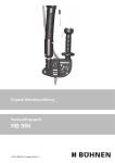
Operating Original operating instructions instructions Manual application unit with radio control Manual application unit Type HR (paste) HB 950 Type HS (spray) WCH1186XE.01(Issue09-2011) Table of Contents 1 General 1.1 Operative range 1.2 Technical data 1.3 Product identification 1.4 Pin assignment 1.4.1 1.4.2 3 3 3 3 4 Version WCH1185/1188 (for NS hoses…) Version WCH1186/1187 (for KS hoses…) 4 4 2 2.1 2.2 2.3 3 3.1 3.2 4 4.1 4.2 5 5.1 5.2 5.3 6 6.1 6.2 Security advice Possible dangers Intended use Notes on safe operation Construction and operating elements Introduction Operating elements Initial operation Installation Setting the temperature Operation General notes Discharging the hot melt material Setting the spray pattern (WCH 1187/1188 only) Maintenance/servicing Maintenance intervals Cleaning 5 5 5 6 6 6 7 8 8 9 10 10 10 11 12 12 12 7 8 8.1 8.2 8.3 8.4 9 10 11 12 12.1 12.2 13 What happens if… Accessories Balancer Swivel arm with balancer Assembly dolly Air hose Repairs Warranty Disposal Spare parts Spare parts for paste Spare parts for spray Declaration of Conformity 13 14 14 14 14 14 14 14 14 15 16 17 19 6.2.1 Clean nozzle 2 12 General 1 General 1.1 Operative range 1.2 Technical data Please read these operating instructions carefully and thoroughly before operating the applicator for the first time. Also, pay particular attention to the security advice in Chapter 2. These operating instructions must be accessible at all times to every user. Also take note of the operating instructions on the • tank system and the • heatable hose, especially the security advice contained therein. The HB 950 manual applicator is used to apply (point/paste form or as spray) regulated amounts of hot melt adhesives with exchangeable nozzles on horizontal surfaces (intended use). The spray version can be retrofitted to the paste version at any time by changing the module and the nozzle (see Figure 9 on page 16). Designation Parts No. Paste version WCH 1186 Spray version WCH 1185 Supply voltage WCH 1187 230 V AC/50…60 Hz Weight 1,500 g Heating capacity 200 W Protection class (in acc. with DIN VDE 0720) 300 W I (Protective conductor terminal) Max. operating temperature 200 °C Type of heating High-performance heating cartridge Temperature sensor Pt100 Ni120 Pt100 Max. adhesive pressure Nozzle Ni120 100 bar Spray air pressure 5.0…6.0 bar Paste nozzle, long with UNF 3/8" thread Available nozzle Ø 1.3 WCH 1188 Spray nozzle 0.2…2.0 mm Product identification These operating instructions apply to all manual application units with the following illustrated type plate. The type plate is located on the side of the housing. BÜHNEN GmbH & C0. KG Hinterm Sielhof 25 28277 Bremen • Germany www.buehnen.de WCH1186 Typ Ser.-Nr. Fühler Pt100 200 °C max. Temp. Figure 1:Type plate on unit 3 230 V 200 W General 1.4 1.4.1 Pin assignment Version WCH1185/1188 (for NS hoses…) Pin type: 6-pin, rectangle, plug cable side manual application unit 4 5 2 1 3 Pin Colour Function 1 orange Heater applicator head (L) 2 grey Heater applicator head (N) 3 red Applicator head sensor 4 5 1.4.2 red Applicator head sensor green/yellow Protective earth Version WCH1186/1187 (for KS hoses…) Plug type:8-pin, Harting, plug cable side manual application unit 7 6 5 4 PE 2 3 1 Pin Colour Function 1 free 2 orange Heater applicator head (L) 3 grey Heater applicator head (N) 4 free 5 free 6 white Applicator head sensor 7 red Applicator head sensor 8 green/yellow Protective earth 4 Security advice 2 2.1 Security advice Possible dangers Danger! Never point the operational device at other people. Danger due to high pressure! Danger of burns! The nozzle and melted hot melt adhesive can be hotter than 200°C. Wear heat protection gloves if contact is unavoidable. Irritating Danger due to vapours! PU hot melt adhesives give off harmful vapours (isocyanates) even when applied in accordance with instructions. If the prescribed processing temperature is exceeded for a longer period, harmful decomposition products will develop. For your safety, please observe the following notes: • Make sure there is sufficient ventilation (S set 51). • Do not inhale vapours and atomised sprays (S set 23). • Do not smoke, eat or drink during work (S set 20/21). Measures for First Aid After skin contact: After contact with eyes: If you feel unwell after inhaling vapours: After swallowing: 2.2 Cool the affected areas immediately with plenty of cold water. Rinse your eyes immediately with running water for several minutes. Have a doctor remove the cooled adhesive. Provide fresh air. If you continue to feel unwell, consult a doctor. If you continue to feel unwell, consult a doctor. Intended use The manual application unit is used to apply regulated amounts of hot melt materials (thermoplastic materials such as hot melt adhesives, waxes, etc.) in paste form or as a spray to horizontal surfaces. When processing reactive hot melt adhesives, such as polyurethane (PU) hot melt adhesives, we recommend placing the nozzle in a paraffin oil bath during longer work breaks. Attention! The HB 950 manual application units are only approved for operation with heatable hoses of the type BÜHNEN KS and NS. Separation from and connection to heatable hoses may only be implemented by competent personnel with electrical skills. 5 Construction and operating elements 2.3 Notes on safe operation 3 Construction and operating elements 3.1 Always comply exactly with the following notes as protection from disruptions and faulty operation: • The maximum permissible operating pressure of the hot melt adhesive (100 bar) may not be exceeded in any case. • Remove combustible or heat-sensitive objects from the range of the nozzle. • Protect the device from moisture and wetness (protection from electric shock). • Observe the processing bulletin of the hot melt material (protection from processing errors). • Disconnect the device from the power supply (plug connection at heatable hose) before every device intervention (maintenance, cleaning). • Before storage, permit the device to cool down completely. • If you notice damage on the device or the supply cables, disconnect the power supply immediately. Have a specialist check the device at once. It may only be put back into operation after proper repairs (see chapter 9). • Never point the operational application unit towards yourself or at other persons. Introduction The HB 950 manual applicator was specifically developed for manual applications with high ergonomic demands. It is well suited to apply hot melt adhesive to horizontal surfaces and dimensions up to 1,000 mm. A balancer must be used to exploit the advantages, preferably a balancer on a swivel arm, see Chapter 8, Accessories. This compensates the weight of the applicator and the heatable hose and the device is always close to hand. The balancer also protects the device from falling down accidentally and thus protects it from damage. Triggering occurs pneumatically through an installed 3/2-way valve. The applicator therefore needs an air supply, either by using the heatable hose from the spray version, or by using an additional air hose. 6 Construction and operating elements 3.2 Operating elements Figure 2:Operating elements Cons. No. Designation 1 Suspension eye for balancer 2 Trigger 3 Handle 4 Connection for hot melt adhesive hose 5 Electrical connector plug 6 Adjusting screw for spray air ( WCH 1187 and WCH 1188 only) 7 Initial operation 4 Initial operation Attention! Initial operation may only be implemented by competent personnel. 4.1 Installation Required tools • 2 open-end wrenches, size 19 1. Screw the hose onto the threaded nipple using the size 19 open-end wrench. 2. Lock the threaded nipple with a second size 19 open-end wrench (see Figure 3). Figure 3:Mount hose connection 3. Insert the electrical connection in the plug connector of the heatable hose (see Figure 4). Figure 4:Connect the electrical connection to the mains 4. Hold the HB 950 by its support. Connect the steel cable of the balancer to the support. 5. Connect the 6 mm PTFE air hose coming from the heatable hose to the corresponding connector of the HB 950 (see Figure 5). Figure 5:Connect the compressed air supply 8 Initial operation 6. Make sure that the heatable hose is connected to the tank system. Establish the power supply. 7. Switch on the system. Adjust the temperature to the temperature recommended by the manufacturer of the hot melt adhesive (see data sheet). 8. The system now begins to heat up. 9. After the required temperature is reached, retighten all hydraulic hose connections. 10. Mount the enclosed protection against contact at the hydraulic connection between the hose and the HB 950. Tighten the screws illustrated (see Figure 6). Figure 6:Install the protection against contact 11. Begin with low pump pressure to prevent hot melt adhesive from discharging uncontrollably (pump pressure 0.5 - 1 bar). 12. Install the nozzle appropriate to your purpose. 13. Set the required flow rate at the tank system. 14. The system is now ready for use. 4.2 Setting the temperature The temperature of the hot melt material is set using the control electronics of the tank system. Info Please do not set the temperature higher than the processing temperature prescribed/ recommended by the manufacturer. This prevents thermal damage to the hot melt adhesive. The manual application unit has its own heater that is only used to retain the temperature of the hot melt material. It is not possible to additionally heat up the hot melt material in the manual application unit. In normal operation, the hot melt material flows through the heating element too quickly for that. 9 Operation 5 Operation Attention! Operation may only be implemented by competent personnel. 5.1 General notes Wear safety gloves! Danger of burn injuries due to hot metal parts, in the area of the heat insulation, and due to the discharged hot melt material. To avoid burning yourself while operating the manual application unit, always wear heat protection gloves. Xi Danger of mucous membrane irritation due to vapours! Even during prescribed processing, hot melt adhesives give off vapours that can have an annoying odorous effect. Therefore, only operate the tank system in well ventilated rooms. Observe the processing bulletin and the safety data sheet of the hot melt adhesive manufacturer. • Immediately turn off the tank system if the function is disrupted. Have qualified personnel check the tank system. 5.2 Discharging the hot melt material To discharge the hot melt material, carry out the following work steps: 1. Make sure that the tank system with all components has been thoroughly heated (approx. 30…45 min after turning on). 2. Press the trigger ➋ (see Figure 2). 3. Regulate the discharge amount by pressing the trigger for longer/shorter periods. The discharge amount can be additionally varied by • selecting another nozzle, • moving the nozzle more slowly or more quickly over the work piece, • changing the processing temperature, or • changing the operating pressure (max. 100 bar). 10 Operation 5.3 Setting the spray pattern (WCH 1187/1188 only) Required tools • 1 Allen key 4 mm The spray pattern depends on the operating pressure of the tank system and the spray air pressure setting. Determine the optimum setting by turning the adjusting screw (see Figure 7) and repeated trials. - Figure 7:Setting the spray air 11 + Maintenance/servicing 6 Maintenance/servicing Danger! Danger due to electric voltage. All work that requires the device to be opened may only be performed by qualified personnel with electrical skills. Danger of burns! The nozzle and hot melt adhesive can be hotter than 200°C. Therefore, always wear heat protection gloves during maintenance and servicing work. 6.1 Maintenance intervals Comply with the listed maintenance intervals to ensure continuous faultless and safe operation: Daily: Check nozzle system for passage (visual check) Clean the nozzle system as necessary Weekly: 6.2 Inspect all attachments for correct seat and leak tightness (visual check) Cleaning • Do not use any aggressive solvent to clean the device. This could damage the device components. For cleaning, we recommend Bühnen cold cleaner (Art.-No. F91500). • Replace complete parts that cannot be cleaned (e.g. due to burned or reacted hot melt material). We recommend you have BÜHNEN Service perform this work. • Remove hot melt material residues and other pollution through exclusively mechanical means, e.g., with a cloth, soft brush, wood spatula, or similar. 6.2.1 Clean nozzle Required tools • 1 open-end wrench 11 mm Danger of burns! The module and hot melt adhesive can be hotter than 200°C. Therefore, always wear heat protection gloves for the following work. 12 What happens if… 7 What happens if… For occurring malfunctions and faults, first check • the power supply and all electrical connections • whether the main switch and the pump switch have been turned on • whether the temperature values for the utilized hot melt adhesive have been set correctly Fault Possible cause Remedy No hot melt adhesive discharge Temperature too low Wait until the HB 950 has reached its operating temperature. Air pressure too low To open the module, the pressure must be set to ±6 bar. Pump pressure too low Increase the pump pressure and check if the tank system reports "ready". Clogged nozzle Clean or replace nozzle. Module defective Replace module. Depressurise the system for this! Spray version only: Air pressure too high for spray effect Reduce the air pressure. HP 950 does not heat. Plug connector (6-pin) not inserted Check and insert correctly. correctly Individual pins have no contact. Check if all pins in the plug are positioned correctly. Heating element defective Measure the resistance between Pin 1 and 2. If there is no measurable resistance, the heating element is defective. Sensor/temperature error Plug connector (6-pin) not inserted Check and insert correctly. correctly Individual pins have no contact. Check if all pins in the plug are positioned correctly. Sensor defective Measure the resistance between Pin 3 and 5. If there is no measurable resistance, the sensor is defective. 13 Accessories 8 8.1 Accessories Balancer Art.-No. Balancer 8.2 590031 Swivel arm with balancer Art.-No. Swivel arm with balancer 8.3 FCH0487 Assembly dolly Art.-No. Mobile assembly dolly 800 FCH0488 x 600 mm 9 Repairs 10 Warranty 11 Disposal Repairs other than those described in these operating instructions may only be implemented by competent persons commissioned by the manufacturer or otherwise competent persons under utilization of original Bühnen spare parts. The unit was developed and manufactured according to the latest state of technology. The first purchaser receives warranty on function, material, and workmanship according to statutory regulations. Normal wear and tear is excepted. The warranty is void if improper handling, use of violence, repairs by third parties and the installation of spare parts other than the original has been determined. The warranty extends to servicing or replacement according to our choice. Warranty beyond our scope of delivery is excluded, as we do not have any influence on the competent and expert use of the unit. Please observe our terms and conditions! Take the unit, packaging, and accessories to an environmentally friendly recycling centre (in accordance with Directive 2002/96/EC of the European Parliament and the Council of 27. January 27, 2003). 14 Spare parts 12 Spare parts Figure 8:Spare parts. Part A Cons. No. Parts No. Designation 1 KDN0738 Allen screw M5 x 20 2 B35-500-0017 HB 950 suspension 3 B35-500-0002 Festo air valve TH3-M5 4 B35-500-0009 Air supply M5 5 KDN0553 Allen screw M4 x 30 6 B35-500-0006 HB 950 handle 7 B10-002-0032 O-ring 5.0 x 1.5 15 Spare parts 12.1 Spare parts for paste Figure 9:Spare parts for paste, Part B Cons. No. Parts No. Designation 1 B35-500-0011 Rear cover 2 B35-500-0013 Front cover 3 B35-500-0012 Module cover 4 B35-500-0008 HB 950 body 5 KDN0723 Stainless steel Allen screw M6 x 40 (to assemble the handle) 6 B24-010-0032 Heat-proof plug connection 6 mm x 1/8" 90° 7 B35-500-0018 (Set) compressed air bends, 2x compressed air connectors (straight and 90°) 8 NKT0106 Module 9 Nozzle (at buyer's choice) 16 Spare parts 12.2 Spare parts for spray Figure 10: Cons. No. Spare parts for spray, Part B Parts No. Designation 1 B35-500-0111 Rear cover 2 B35-500-0113 Front cover 3 B35-500-0112 Module cover 4 B35-500-0108 HB 950 body 5 KDN0723 Stainless steel Allen screw M6 x 40 (to assemble the handle) 6 B24-010-0032 Heat-proof plug connection 6 mm x 1/8" 90° 7 B35-500-0018 (Set) compressed air bends, 2x compressed air connectors (straight and 90°) 8 NKT0108 Spray module 17 Spare parts Figure 11: Cons. No. Spare parts, Part C Parts No. Designation 1 B23-004-0600 Cable set 60 cm, PG7 screw connection 2 B12-001-0001 Sensor Pt-100 2 BRTD 2300 Sensor Ni-120 3 B53-050-0200 Heating element 200 W, Ø 3/8”, 230 V 3 B53-050-0300 Heating element 300 W, Ø 3/8”, 230 V 18 Declaration of Conformity 13 Declaration of Conformity Declaration of Conformity Bühnen GmbH & Co. KG We, the D-28277 Bremen declare on our sole responsibility that the product Manual Applicator Type HB 950 to which this declaration refers, complies with the following Standards or normative documents in its supplied condition: EN ISO 12100-1, -2 EN 55011 EN 60204-1 in accordance with the stipulations of guideline 2001/95/EC 2002/95/EC 2002/96/EC 2004/108/EC 2006/95/EC Bremen, February 2011 Hermann Kruse Technical Manager & Documentation Representative 19 Hanno Pünjer General Manager Hinterm Sielhof 25 D-28277 Bremen • Germany Phone:+49 (0) 421 51 20 - 125 Fax: +49 (0) 421 51 20 - 260 [email protected] www.buehnen.de Subject to change © BÜHNEN GmbH & Co. KG/WCH1186XE.01EN_110913/H&F BÜHNEN GmbH & Co. KG