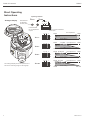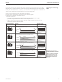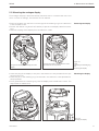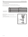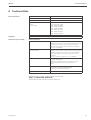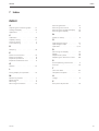
1
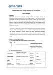
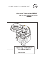
Pressure Transmitter PM 3X PM 3X with analogue electronics Zero Span fine 1 2 + 3 – coarse t 1 2 3 Display Operating instructions 9499-040-64511 Valid from :8380 Table of Contents PM 3X Short Operating Instructions Analogue display Operating elements Zero Potentiometer for adjusting the zero point Span fine coarse 1 2 3 t off on Potentiometer for fine adjustment of span Keys for coarse calibration of the span 1 2 3 Zero + – 3 coarse t 1 2 3 off on TD 1:1 Display 1 2 3 t off on TD 3:1 1 2 3 t TD 6:1 The analogue display shows the pressure as a ratio of the measuring range on the bargraph. 2 TD 10:1 4 mA Basic setting 0 bar 0.3 bar off on 20 mA Fine adjustment 1 bar TD 3:1 1 4 mA Coarse adjustment 20 mA Fine adjustment 1 bar TD 6:1 4 mA Basic setting 0 bar 0.1 bar t 1 bar TD 1:1 0 bar 0.15 bar off on 1 2 3 Fine adjustment 0 bar Span fine 1 2 t 20 mA Fine adjustment 1 bar TD 10:1 4 mA Basic setting 20 mA PMA GmbH PM 3X Table of Contents TABLE OF CONTENTS 1 Notes on Safety . . . . . . . . . . . . . . . . . . . . . . . . . . . . 5 1.1 Notes on Safety . . . . . . . . . . . . . . . . . . . . . . . . . . . . 6 2 Introduction . . . . . . . . . . . . . . . . . . . . . . . . . . . . . . 7 3 Installation. . . . . . . . . . . . . . . . . . . . . . . . . . . . . . . 8 3.1 3.2 3.3 3.4 Mounting instructions without diaphragm seal . . . . . . . . . . . . . . . . 8 Mounting instructions with diaphragm seal . . . . . . . . . . . . . . . . . 10 Mounting accessories . . . . . . . . . . . . . . . . . . . . . . . . . 12 Electrical connection . . . . . . . . . . . . . . . . . . . . . . . . . 13 4 Operation and Start-Up . . . . . . . . . . . . . . . . . . . . . . . . 14 4.1 Access to the operating elements and the function of the analogue display . . . . 14 4.2 Position and function of the operating elements on the electronic insert . . . . . . . . . . . . . . . . . . . . . . . . . . . . . 15 4.3 Calibration and start-up . . . . . . . . . . . . . . . . . . . . . . . . 16 5 Maintenance and Repair . . . . . . . . . . . . . . . . . . . . . . . 18 5.1 5.2 5.3 5.4 Repair . . . . . . . . . . Mounting the analogue display Replacing the electronic insert. Changing the gasket . . . . . . . . . . . . . . . . . . . . . . . . . . . . . . . . . . . . . . . . . . . . . . . . . . . . . . . . . . . . . . . . . . . . . . . . . . . . . . . . . . . . . . . . 18 19 20 21 6 Technical Data . . . . . . . . . . . . . . . . . . . . . . . . . . . . 23 7 Index . . . . . . . . . . . . . . . . . . . . . . . . . . . . . . . . . 25 PM 3X 3 Table of Contents 4 PM 3X PM 3X PM 3X 1 Notes on Safety The PM 3X is a pressure transmitter for measuring gauge or absolute pressure depending on the version. Approved usage The PM 3X has been designed to operate safely in accordance with current technical, safety and EU standards. If installed incorrectly or used for applications for which it is not intended, however, it is possible that application-related dangers may arise, e. g. product overspill by incorrect installation or adjustment. For this reason, the instrument must be installed, connected, operated and maintained by personnel that are authorised by the user of the facility and who are suitably qualified. The manual is to be read and understood, and the instructions followed. Modifications and repairs to the device are permissible only when they are expressly approved in the manual. Mounting, commissioning, operation The measuring system used in the explosion-hazardous area must comply with all existing national standards. The instrument can be supplied with the following certificates as listed in the table. The certificates are designated by the first letter of the order code on the nameplate (see table below). Explosion-hazardous area Ensure that technical personnel are sufficiently trained. All measurement and safety regulations which apply to the measuring points are to be observed. PM3X Order No. P M 3 X Code - Certificate Protection 0, 2, 4, 6, Standard None 1, 3, 5, 7, ATEX 100 ATEX II 1/2 G EEX ia IIC T6 PMA GmbH Certificates for applications in explosion hazardous areas 5 PM 3X 1.1 Notes on Safety In order to highlight safety-relevant or alternative operating procedures in the manual, the following conventions have been used, each indicated by a corresponding icon in the margin. Notes on safety Symbol Meaning Note! A note highlights actions or procedures which, if not performed correctly, may indirectly affect operation or may lead to an instrument response which is not planned. Caution! Caution highlights actions or procedures which, if not performed correctly, may lead to personal injury or incorrect functioning of the instrument. Warning! A warning highlights actions or procedures which, if not performed correctly, will lead to personal injury, a safety hazard or destruction of the instrument. Explosion protection Device certified for use in explosion hazardous area If the device has this symbol embossed on its name plate it can be installed in an explosion hazardous area. Explosion hazardous area Symbol used in drawings to indicate explosion hazardous areas. Devices located in and wiring entering areas with the designation “explosion hazardous areas” must conform with the stated type of protection. Safe area (non-explosion hazardous area) Symbol used in drawings to indicate, if necessary, non-explosion hazardous areas. Devices located in safe areas still require a certificate if their outputs run into explosion hazardous areas. Electrical symbols Direct voltage A terminal to which or from which a direct current or voltage may be applied or supplied. Alternating voltage A terminal to which or from which an alternating (sine-wave) current or voltage may be applied or supplied. Grounded terminal A grounded terminal, which as far as the operator is concerned, is already grounded by means of an earth grounding system. Protective grounding (earth) terminal A terminal which must be connected to earth ground prior to making any other connection to the equipment. Equipotential connection (earth bonding) A connection made to the plant grounding system which may be of type e.g. neutral star or equipotential line according to national or company practice. 6 PMA GmbH PM 3X 1 Introduction 2 Introduction The PM 3X pressure transmitter measures the pressure of gases, vapours and liquids and is used in all areas of chemical and process engineering. Application Ceramic sensor The system pressure acts directly on the rugged ceramic diaphragm of the pressure sensor deflecting it by a maximum of 0.025 mm (0.0098 in). A pressure-proportional change in the capacitance is measured by the electrodes on the ceramic substrate and diaphragm. The measuring range is determined by the thickness of the ceramic diaphragm. Operating principle Metal sensor The process pressure deflects the separating diaphragm with a filling liquid transmitting the pressure to a resistance bridge. The bridge output voltage, which is proportional to pressure, is then measured and processed. Ceramic sensor Metal sensor Ceramic substrate Resistance bridge Diaphragm Filling fluid Electrode The complete measuring system in a simple application consists of · a PM 3X pressure transmitter with 4…20 mA signal output and · a power supply of 11.5…45 V . An optional analogue display can be directly plugged onto the electronic insert using a holder. It shows the pressure on a bargraph as a ratio of the measuring range. Measuring system DC PM 3X 4…20 mA 11.5…45 VDC Process PMA GmbH 7 2 Installation PM 3X 3 Installation Contents This section describes: · the mechanical installation of PM 3X with and without diaphragm seal, · the electrical connection. 3.1 Mounting instructions without diaphragm seal PM 3X without diaphragm seal – PM31, 32 – PM33, 34 The PM 3X without diaphragm seal is mounted in the same way as a manometer. The use of shut-off valves and pigtails is recommended. The position depends upon the application. · Measurement in gases: Mount on the shut-off valve above the tapping point so that condensate can run back into the process. Figure 2.1 Mounting on a shut-off valve for measuring gases · Measurement in steam: Mount with a pigtail above the tapping point. The pigtail reduces the temperature in front of the diaphragm to almost ambient temperature. Before start-up, the pigtail must be filled with water. Figure 2.2 left: Mounting with a U-shaped pigtail for measuring steam right: Mounting with a circular pigtail for measuring steam 8 PMA GmbH PM 3X 2 Installation · Measurement in liquids: Mount on the shut-off valve below the tapping point or at the same height. Figure 2.3 Mounting on a shut-off valve for measuring liquids Mounting the PM31 The PMP 41 with metal sensor is available in the following versions: · with flush-mounted diaphragm or · with adapter and internal diaphragm. The adapter can be screwed on or welded in. A gasket is enclosed according to the material used and version. G ½ external with O-ring 15 21 17 3 21.3 19.4 4,3 G½ Ø 26.4 50 Viton seal O-ring 14 x 1.78 Viton or NBR Teflon Hastelloy spring Viton seal PMA GmbH G½ Ø 26.4 Ø 26.4 Teflon back-up PTFE seal 17 3 17 3 27 21 2.5 Threaded hole DIN 3852-X-G ½ 14 Screwed plug DIN 3852-E-G ½ 22 G ½ external G½ Dimensions 1 in = 25.4 mm 1 mm = 0.039 in Welded nozzle Figure 2.4 PM31 with flush-mounted diaphragm above: G ½ external with O-ring below: G ½ external 9 2 Installation PM 3X Process connection flush-mounted diaphragm Welded Seal supplied Figure 2.5 PM 33 with screwed or welded adap ter. With welded adapter max. tor que 80 Nm With adapter internal diaphragm 3.2 Mounting instructions with diaphragm seal PM 35 with diaphragm seal – PM36 The PM 3X with diaphragm seal is screwed in, flanged or clamped, depending on the type of diaphragm seal. PM35 with screw cap PM36with flange PM35 with clamp Figure 2.6 Diaphragm seal versions · The protective cap of the diaphragm seal should only be removed just before mounting in order to protect the diaphragm. · The diaphragm of the diaphragm seal of the PM 3X must not be dented or cleaned with pointed or hard objects. · The diaphragm seal and the pressure sensor together form a closed and calibrated system which is filled with filling fluid through a hole in the upper part of the sensor. The following rules should be observed: - This hole is sealed and is not to be opened. - The instrument should only be turned by the diaphragm seal at the point provided and not by the housing. 10 PMA GmbH PM 3X 2 Installation Mounting with temperature spacers 100 The use of temperature spacers is recommended for constant extreme product temperatures that can cause the maximum permissible ambient temperature of +85°C (+185°F) to be exceeded. · Note when mounting that the temperature spacer increases the maximum height by 100 mm (3.94 in). · Due to the water column in the temperature spacer, the increased height also causes a zero point shift of approx. 10 mbar (0.15 psi). Figure 2.7 Mounting with temperature spacers To protect from high temperature, moisture or vibration, or where the mounting point is not easily accessible, the housing of the PM 3X can be mounted with a capillary tube to one side of the measuring point. A bracket for mounting on a wall or pipe is available for this. Mounting with capillary tubing 3.3 Mounting accessories Measuring point: – very moist – hot – strongly vibrating – difficult to access 60.3 26 81 70 101 (121) 184.5 Dimensions 1 in = 25.4 mm 1 mm = 0.039 in 119.5 Mounting point away from the measuring point 3 26 101 (121) 167 102.5 PMA GmbH Figure 2.8 Mounting with capillary tubing and bracket away from the measuring point. Values in brackets apply to in struments with a raised cover. 11 2 Installation PM 3X PM31 Wall and pipe mounting with bracket 159 97 (117) 98 (118) 32 32 176 3 81 70 60.3 94 111 60.3 6 Figure 2.9 Mounting with bracket left: on a vertical pipe right: on a wall. Values in brackets apply to in struments with a raised cover. PM33 wall and pipe mounting with bracket 113(133) 114 (134) 26 26 81 70 Dimensions 1 in = 25.4 mm 1 mm = 0.039 in 167.5 184.5 3 60.3 119.5 102.5 12 6 60.3 Figure 2.10 Mounting with bracket left: on a vertical pipe right: on a wall. Values in brackets apply to in struments with a raised cover PMA GmbH PM 3X 2 Installation 3.4 Electrical connection Transposed, screened two-wire cabling is recommended for the connecting cable. Max. wire diameter: 2.5 mm2 solid conductor The power supply voltage is: · 11.5…45 V Internal protection circuits against reverse polarity, HF interference and overvoltage peaks (see TI 241F “EMC Guidelines”). A test signal can be measured using the terminal plugs for this purpose without interrupting measurement. DC · Unscrew the cover · If present, remove the retainer ring with analogue display. In addition: – Push up the catch with the arrow until the grip of the retaining ring is audibly released. – Loosen the retainer ring carefully to prevent the display cable from breaking. The plug of the display can remain plugged in. · Insert the cable through the cable entry · Connect the cable wires as shown in the connection diagram. · Where appropriate, replace the retainer ring with an analogue display. The grip of the retainer right clips in with an audible click. · Screw down the cover B Cable connection Test 4…20 mA 1 2 3 +– * Figure 2.11 Electrical connection Analogue electronics * For versions with certificate ATEX 100, II1/3D (not Ex po wer supply) the instrument must always be protected by a 50 mA (slow-blow) fuse. T 50 mA Span Zero fine 1 2 3 + + – coarse t 1 2 3 – Display Always connect the potential compensation line (if present) to the internal ground terminal of the housing, not to Terminal 3. To loosen the holder from the electronic insert, push latch with arrow upwards. BA200Y15 Plug Harting plug Plug assignment Terminal Function Wire colour code 1 2 8 + – PE Blue (BL) Brown (BN) Green-Yellow (GNYE) 7 6 8 1 5 2 3 4 Plug M 12x1 Terminal 3 on the electronic in sert is for grounding and is al ready wired internally. If the connecting cable also has a screening or ground cable wit hin it, then this may only be connected to the internal ground terminal of the housing, not to Terminal 3 (see circuit diagram). + – PE Red (RD) Black (BK) Green (GN) – + PMA GmbH 13 3 Operation and Start-Up PM 3X 4 Operation and Start-Up This section describes: · Access to the operating elements and the function of the analogue display · Position and function of the operating elements on the electronic insert · Calibration and start-up of the PM 3X 4.1 Access to the operating elements and the function of the analogue display Lifting display for operation The analogue display is delivered already mounted when it is ordered with the instrument. The analogue display with the retaining ring must therefore be removed before operating. If you want to order an analogue display at a later date, then please observe the instructions in Section 4.3 “Mounting the analogue display”. Removing the display: · Push up the catch with the arrow until the grip of the retaining ring on the electronic insert clicks. · Loosen the retainer ring and lift off carefully to prevent the display cable from breaking. · For reading the display during operation, plug the display onto the edge of the housing or let it hang down loosely by its cable next to the housing. Zero Span fine 1 2 + Figure 3.1 left: Loosening the retaining ring right: Lifting off the display with retai ning ring for operation To loosen the holder from the electronic insert, push catch with arrow upwards. 3 – coarse t 1 2 3 Display Lifting off the display with retaining ring for operation. Function of the display –Bargraph as trend display of measuring range 0…100 %. This corresponds to a current output of 4…20 mA –The bargraph and scale flash on signal overrun (current larger than 20 mA). 0% 50% 0…1 bar 100% –Scale –The scale flashes on underrun (current smaller than 4 mA). –Cell measuring range Figure 3.2 Function of the display 14 PMA GmbH PM 3X 3 Operation and Start-Up 4.2 Position and function of the operating elements on the electronic insert À Potentiometer for  Potentiometer for zero point calibration fine adjustment of span Zero 1 2 Connection terminals for measuring the signal current 3 Á DIP switches for Span fine coarse adjustment of span coarse t 1 2 Position of the operating elements 3 à DIP switches for + adjusting the damping Display – Function of the operating elements No. Operating element Function À Potentiometer for zero point calibration Calibration of zero point ±10 % Á DIP switches for coarse calibration of the measuring span For coarse calibration of the measuring span a spread between 1:1 and 10:1 can be selected Switch positions: 1:1 1 2 3 t off on 3:1 1 2 3 t off on 6:1 1 2 3 t off on 10:1 1 2 3 t off on  Potentiometer for fine calibration of the measuring span à DIP switches for calibrating damping Fine adjustment of the measuring span 1 2 3 t off on PMA GmbH off: Damping 0 s on: Damping 2 s 15 3 Operation and Start-Up PM 3X 4.3 Calibration and start-up Preparatory work · Connect up electrically the PM 3X (see sect. 2.4 “Electrical connection”) · Connect a multimeter (4…20 mA) to the connection terminals provided. · Ensure that a pressure can be generated within the required measuring range. Damping The damping t affects the speed with which the output signal and the analogue display react to changes in pressure. A DIP switch unit is available for calibrating the damping: 1 2 3 t off on · Switch position off: · Switch position on: Damping 0 s Damping 2 s Example The example used here is for calibrating a 0…1 bar measuring cell. Zero point adjustment Zero point calibration is carried out using the potentiometer for zero point adjustment. Carry out the zero point adjustment as follows: · Enter exactly 0 bar for the zero point (ambient pressure for gauge measurements or vacuum for absolute measurements). · Adjust the multimeter to exactly 4 mA. Pressure 0 bar Current Set to exactly 4 mA Response of analogue display Display of 0 % 0% 50% 100% The scale does not flash. (The scale begins to flash immediately a point is set which is below the cell measuring range. In this case readjust the value until the scale stops flashing.) 16 PMA GmbH PM 3X 3 Operation and Start-Up Three DIP switches are available for course adjustment of the measuring span. Depending on the switch position, a measuring range spread (also known as turndown or TD) can be selected for 1:1 (to 2:1), 3:1, 6:1 or 10:1. Fine adjustment is carried out using the fine adjustment potentiometer of the measuring span. Adjusting the measuring span Carry out the measuring span adjustment as follows: · Enter exactly the pressure required for the measuring span. · Adjust the multimeter to exactly 20 mA. Proceed as follows: – Limit the measuring span by selecting one of the measurement range spreads using the DIP switches for coarse adjustment. – Adjust exactly the measuring span required using the potentiometer for fine adjustment of the measuring span. DIP switch positions TD 1:1 1 2 3 Pressure Response of the analogue display Cell measuring range: 0…1 bar Measuring range set: 0…1 bar t off on 0 bar 1 bar Pressure Current 1 2 3 0% TD 1:1 4 mA TD 3:1 Display of 100 % 20 mA Cell measuring range: 0…1 bar Coarse measuring range set: 0…0.3 bar (TD 3:1) t off on 0 bar 0.3 bar 1 bar Pressu0% TD 3:1 4 mA 1 2 3 20 mA Cell measuring range: 0…1 bar Coarse measuring range set: 0…0.15 bar (TD 6:1) t off on 0 bar 0.15 bar 4 mA off on 20 mA 0 bar 0.1 bar Display of 100 % 50% 100% The bargraph does not flash.* Display of 100 % * Bargraph and scale begin to flash immediately a full scale 1 bar Pressu0% TD 10:1 Current 4 mA PMA GmbH The bargraph does not flash.* 0% Cell measuring range: 0…1 bar Coarse measuring range set: 0…0.1 bar (TD 10:1) t 100% 1 bar TD 6:1 1 2 3 50% Pressure Current TD 10:1 100% Display of 100 % Current TD 6:1 50% The bargraph does not flash.* 20 mA 50% 100% The bargraph does not flash.* value is set which exceeds the cell measuring range. In this case read just the value until the bargraph and scale stop flashing. 17 4 Maintenance and Repair PM 3X 5 Maintenance and Repair 5.1 Repair If the PM 3X must be sent to PMA GmbH for repair, then a note should be enclosed containing the following information: · An exact description of the application · The chemical and physical characteristics of the product. · A brief description of the error. Before sending in the PM 3X to PMA GmbH for repair, please take the following protective measures: · Remove all traces of the product. This is particularly important if the product is dangerous to health, e.g. corrosive, poisonous, carcinogenic, radioactive, etc. · We do request that no instrument should be returned to us without all dangerous material being completely removed as it can, e.g. penetrate into fissures or diffuse through plastic. Caution! Instruments with certificates of conformity or design approval must be sent in for repair as complete units only. Note! In case of malfunction do not hesitate to contact our PMA-service. 18 PMA GmbH PM 3X 4 Maintenance and Repair 5.2 Mounting the analogue display The analogue display is delivered already mounted when it is ordered with the instrument. In cases of damage, accessories can be ordered. · Push up the latch with the arrow until the grip of the retaining ring on the electronic insert is heard to click. · Loosen the retainer ring and lift off carefully to prevent the display cable from breaking. · Remove the plug of the display from the electronic insert. Zero Span fine 3 1 2 coarse t 1 2 3 Display – + Lifting off the display and removing the of the display. To loosen the holder from the electronic insert push catch with arrow upwards. · Insert the plug of the display in the jack in the electronic insert provided for this purpose and clip in À. · Insert the pin on the retaining ring into the hole in the electronic insert provided for this purpose Á. · Firmly press down the retaining ring with the display onto the electronic insert. The stop makes an audible click. Zero Span fine 1 2 + Removing the display – 3 coarse t 1 2 3 À Figure 4.1 rightl: Loosening the retaining ring left: Removing the display Mounting the display Á Display Figure 4.2 Mounting the display PMA GmbH 19 4 Maintenance and Repair PM 3X 5.3 Replacing the electronic insert · If the existing analogue electronic insert is to be replaced with another analogue electronic insert, then it can be ordered : Electronics PM 3X, 4…20 mA, analogue After replacing the electronic insert the instrument must be recalibrated. Information on adjustment is given in Section 3 “Operation”. · If the existing analogue electronic insert is to be replaced with a digital electronic insert. Removing the electronic insert · If appropriate, loosen the retaining ring and lift off and remove the plug of the display from the electronic insert. · Remove the cable from the electronic insert. · Loosen screws À and Á on the electronic insert. · Lift out the electronic insert. Mounting the electronic insert · Plug in the new electronic insert and tighten screws À and Á. · Connect the connecting cable as shown in connection diagram in Section 2.4 “Electrical Connection”. · Carry out a calibration as shown in Section 3 “Operation”. · If appropriate, mount the display. Á Zero Span fine 1 2 + – 3 coarse t 1 2 3 off on + – Display À Figure 4.3 Position of screws À and Á for removing the electronic insert 20 PMA GmbH PM 3X 4 Maintenance and Repair 5.4 Changing the gasket The gasket in contact with the medium and inside the spigot of the PM 3X PMC 41 can be replaced. Except for the PTFE gasket (Structure D), all gaskets can thus be interchanged as required. The different temperature limits should be observed for individual materials. Gasket * Upper temperature limit according to specifications of standard instrument Temperature limits 1 FPM, Viton –20°C* (–4°F) 6 FPM, Viton grease-free –10°C* (+14°F) A FPM, Viton oil and grease-free for oxygen –10°C…+60°C (+14°F…+140°F) 2 NBR –20°C* (–4°F) 7 FFKM, Kalrez compound 4079 +5°C* (+41°F) 4 EPDM –40°C* (–40°F) Changing the gasket · Loosen the screws on the retaining ring of the process connection. · Remove the retaining ring and the process connection · Replace gasket. The surfaces on each side of the gasket and the gasket itself must be free from dirt fibre and dirt. · Secure the process connection with the retaining ring and screws Gasket Replaceable process connection Holding ring with screws PMA GmbH 21 PM 3X 5 Technical Data 6 Technical Data General information Application Operation and system design Manufacturer PMA GmbH Kassel Instrument Pressure transmitter, analog Designation PM31, PM32, PM33, PM34, PM35, PM36 Technical documentation Version Technical data 9499-040-64511 (0301)english according to DIN 19 259 PM31 : 9498 737 38813 PM32 : 9498 737 38913 PM33 : 9498 737 39013 PM34 : 9498 737 39113 PM35 : 9498 737 39213 PM36 : 9498 737 39313 Measurement of absolute and gauge pressure in gases, vapours, liquids Measuring principle PM31, PM32 with ceramic sensor The pressure causes a slight deflection of the ceramic diaphragm of the sensor. The change in the capacitance is proportional to the pressure and is measured by the electrodes of the ceramic sensor. Volume of chamber: approx. 2 mm (0.078 in ) 3 PM33, PM34, PM35, PM36 with metal sensor 3 The process pressure acting on the metallic separating diaphragm of the sensor is transmitted via a filling fluid to a resistance bridge. The change in the output voltage of the bridge is proportional to the pressure and is then measured. Volume of chamber: smaller than 1 mm (0.039 in ) 3 3 Measuring system PM 3X and power supply e.g. Via TPS 9404-202-08231 transmitter power pack –Calibration via potentiometers for zero point and span –Plug-in analogue display for showing measured values Construction Aluminium- housing:PM31,PM33,PM36 Standard SS housing: PM32,PM34,PM35 for process connections see page 8 Signal transmission 4…20 mA, 2-wire detailed technical data see datasheet over Internet http: // www.pma-online.de observably and/or also to be downloaded can. PMA GmbH 22 PM 3X Index 7 Index INDEX Adjusting the measuring span · · · 17 Analogue display· · · · · · · · · · 14 Application · · · · · · · · · · · · · 7 Mounting bracket · · · · · · · · · 12 Mounting instructions· · · · · · · · 8 Mounting the analogue display · · 19 Mounting the display · · · · · · · 19 C N Calibration · · · · · · · · · · · · · 16 Capillary tubing · · · · · · · · · · 11 Ceramic sensor · · · · · · · · · · · 7 Commissioning · · · · · · · · · · · 5 O A Notes on safety · · · · · · · · · · · 5 D Operating elements · · · · · · · · 14 Operating principle · · · · · · · · · 7 Operation · · · · · · · · · · · · 5, 14 Damping · · · · · · · · · · · · · · 16 R E Electrical connection· · · · · · · · 13 Electrical symbols · · · · · · · · · · 6 Explosion protection · · · · · · · · 6 Explosion-hazardous area · · · · · · 5 G Gasket · · · · · · · · · · · · · · · 21 L Removing the display · · · · · Repair · · · · · · · · · · · · · Replacement parts · · · · · · Replacing the electronic insert · · · · · · · · 19 18 18 20 S Short operating instructions· · · · · 2 Start-up · · · · · · · · · · · · · · 16 T Lifting display for operation · · · · 14 Technical data · · · · · · · · · · · 23 Temperature spacer · · · · · · · · 11 M U Measuring system · · · · · · · · · 7 Metal sensor · · · · · · · · · · · · 7 Mounting · · · · · · · · · · · · · · 5 Mounting accessories · · · · · · · 12 Usage · · · · · · · · · · · · · · · · 5 PM 3X Z Zero point adjustment · · · · · · · 16 23 Subject to alterations without notice. Internet: www.pma-online.de BA 200O/94/EN/ 01.03 52015936 CCS © PMA Prozeß- und Maschinen-Automation GmbH PO-BOX 310 229, D - 34058 Kassel Printed in Germany 9499 040 64511c (0301)