1
FCC Compliance Statement
Model Name:
MX-SDI Series (MX4-SDI)
This device complies with Part 15 of the FCC Rules. Operation is Subject to the following two conductions: (1)
this device may not cause harmful interference, and (2) this device must accept any interference received,
including interference that may cause undesired operations.
WARNING
Unauthorized reproduction of all or part of this manual is strictly prohibited.
The figures in this manual are for illustration purposes only (may differ from the actual product).
The specifications and design of the product are subject to change without prior notice for purposes of
quality improvement.
CAUTIONS
To get the best use out of the product, be sure to read the cautions before using the product. For safety, please
take note of the following.
1
2
3
4
1
2
3
4
5
Instructions before using the product
To prevent electric shock when installing, moving, or opening the DVR and peripheral devices, connect
and disconnect the cables as instructed. All cables must be connected to grounded power outlets.
If the product is installed near a power outlet, make sure it can be unplugged easily.
Do not use the DVR in water or in wet places.
Keep the plastic packing materials used for the DVR or other peripheral devices out of reach of children
(may cause suffocation).
Installation Environment of the DVR
Maintain the following conditions: operating temperature of 5˚C ~ 40˚C; operating humidity of 10% ~ 80%.
Install the DVR in a safe place that is free from external vibration.
Install the DVR in a well-ventilated place.
To protect the hard disk from data loss and breakdown, install the DVR away from magnetic materials.
When using a rack other than the standard one, use a separate table with sufficient spacing, i.e., 60cm
from the floor, 50cm from the ceiling, and 20cm from the side and back walls and other objects.
Safety Notes on the DVR
When installing additional boards and HDD, separate the power cable and turn OFF power supplied to the
DVR completely..
2 Keep the product away from heat-generating devices such as heaters.
3 Do not use a damaged power cord.
4 To prevent problems due to magnetic interference and electric surge, use only grounded cables and
power outlets.
5 If the power cord is connected, do not touch the power unit. If the power cord is connected, electric current
is still flowing internally even after the switch is turned OFF.
6 Do not place a heavy object on top of the product.
7 Do not drop a conductive object in the ventilation holes.
8 Allot sufficient space for system cabling.
9 Use only the parts indicated in the manual. Do not disassemble, repair, or modify the product without
permission.
10 Incorrect system setup may cause malfunction.
11 Shut down the system normally as instructed in the manual.
1
1
2
Safety Notes on the Lithium Battery
Replace lithium batteries as instructed to avoid danger.
Dispose used lithium batteries properly.
【Warnings and Cautions are indicated as follows】
Possible injury or product damage
Risk of minor injury or product damage
1
Operating Instruction & User’s Guide
Cautions for the usage of the product
Information for the usage of the product
2
Operating Instruction & User’s Guide
CONTENTS
CONTENTS
Chapture 1. Introduction ............................................................................ 6
1-1 MX-SDI series Major Features .......................................................................... 6
1-2 About the Product........................................................................................... 7
1-3 Components .................................................................................................. 7
Chapter 2. Installation and Connection ......................................................... 8
1-4 MX-SDI Series Name and Features of each part ................................................. 8
1-4-1 MX-SDI Series Front Panel ..................................................................................... 8
1-4-2 MX4-SDI Channel Rear Panel ................................................................................. 8
1-5 Installation and Connection .............................................................................. 9
1-5-1 Basic Connection ................................................................................................ 10
1-5-2 Connection of Other Devices ................................................................................. 10
Chapter 3. Operation and Setup Tools ....................................................... 11
1-6 MX-SDI series Front Panel Button ................................................................... 11
1-6-1 MX-SDI series Remote Controller ........................................................................... 13
1-6-2 Mouse .............................................................................................................. 13
Chapter 4. DVR Operation Setup ............................................................... 13
1-7 MX-SDI Series Storage Installation ..................................................................
1-8 Power ON. ...................................................................................................
1-9 Storage Setup ..............................................................................................
1-10 Recording Setup ........................................................................................
1-11 Date/Time Setup .......................................................................................
14
15
16
16
16
Chapter 5. System Operation .................................................................... 17
1-12 Starting System and Exiting the System ........................................................ 17
1-13 Monitoring ................................................................................................ 17
1-13-1 Screen Division and Auto Sequence .................................................................... 17
1-13-2 Zoom (x16) ................................................................................................... 17
1-14 System Login ............................................................................................ 17
1-14-1 User Account and Authorization .......................................................................... 18
1-14-2 Login ............................................................................................................. 18
1-14-3 Logout ........................................................................................................... 18
1-15
1-16
1-17
1-18
1-19
System Information View and Display Setup Change .......................................
System Information ....................................................................................
Display Setup ............................................................................................
Audio, Relay .............................................................................................
Search .....................................................................................................
18
19
20
21
21
1-19-1 Calendar Search .............................................................................................. 22
1-19-2 Time Index ..................................................................................................... 22
1-19-3 List All ........................................................................................................... 22
1-20 Log Viewer................................................................................................ 23
1-21 Playback .................................................................................................. 24
1-21-1 Playback status and Playback Speed Control ........................................................ 24
1-21-2 Smart Search .................................................................................................. 25
3
Operating Instruction & User’s Guide
1-21-3 MULTI TIME ................................................................................................... 25
1-21-4 MULTI DAY .................................................................................................... 25
1-21-5 Event............................................................................................................. 25
1-21-6 Panorama Playback ......................................................................................... 25
1-22
1-23
1-24
1-25
1-26
Backup ....................................................................................................
Capture ....................................................................................................
Log Backup ..............................................................................................
Setup Backup ...........................................................................................
PTZ Camera Control...................................................................................
25
26
26
26
27
Chapter 6. Setup .................................................................................... 28
1-27 Time ........................................................................................................ 28
1-28 Definition .................................................................................................. 29
1-28-1 Camera.......................................................................................................... 29
1-28-2 PTZ............................................................................................................... 29
1-28-3 Event Source .................................................................................................. 29
1-28-4 Relay............................................................................................................. 29
1-29 Action .................................................................. Error! Bookmark not defined.
1-29-1 schedule (schedule1 - schedule4) ....................................................................... 30
1-29-2 Event............................................................................................................. 30
1-29-3 Recording....................................................................................................... 30
1-29-4 Alarm ............................................................................................................ 30
1-29-5 Duration ......................................................................................................... 30
1-29-6 Log ............................................................................................................... 31
1-30 Schedule .................................................................................................. 31
1-30-1 Holiday setup .................................................................................................. 31
1-31 Storage .................................................................................................... 32
1-31-1 Max. Recording Days........................................................................................ 32
1-31-2 HDD Overwrite ................................................................................................ 32
1-31-3 Local Storage Management ............................................................................... 32
1-32 Network .................................................................................................... 34
1-32-1 Ethernet ......................................................................................................... 34
1-32-2 DDNS ............................................................................................................ 34
1-32-3 Port ............................................................................................................... 34
1-32-4 E-mail ............................................................................................................ 34
1-32-5 Bandwidth ...................................................................................................... 34
1-32-6 Callback ......................................................................................................... 34
1-33 System ..................................................................................................... 35
APPENDIX ............................................................................................ 36
(1) Recommended HDD ........................................................................................... 36
(2) Recommended PTZ Camera Protocol. .................................................................... 36
(3) Recommended USB2.0 Device ............................................................................. 36
4
Operating Instruction & User’s Guide
Figure List
[Figure 2-3. Terminal Block Description] ............................................................................................... 10
[Figure 4-4. Menu Window] ................................................................................................................... 15
[Figure 4-5. Storage Device New Tab menu] ........................................................................................ 16
[Figure 5-6. Recording Status Window] ................................................................................................. 18
[Figure 5-7. DVR Infomation] ................................................................................................................. 19
[Figure5-8. Search Window] .................................................................................................................. 22
[Figure 5-9. Log Viewer] ........................................................................................................................ 23
[Figure 5-10. Playback Screen] ............................................................................................................. 24
[Figure 5-11. Playback Status and Control bar]..................................................................................... 24
[Figure 5-12. Backup] ............................................................................................................................ 25
[Figure 6-13. Date and Time Window] ................................................................................................... 28
[Figure 6-14. Definition Window] ........................................................................................................... 29
[Figure 6-15. Action Window] ................................................................................................................ 30
[Figure 6-16. Pre/post alarm]................................................................................................................. 31
[Figure 6-17. Schedule Window] ........................................................................................................... 31
[Figure 6-18. Storage Window] .............................................................................................................. 32
[Figure 6-19. Ethernet Window] ............................................................................................................. 34
[Figure 6-20. System Setup Window] .................................................................................................... 35
5
Operating Instruction & User’s Guide
Chapture 1. Introduction
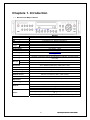
1-1 MX-SDI series Major Features
System
Channel type
OS
Video Input
Monitor
Video
output
Spot
Audio Input
Audio Output
Compression Format
Recording Speed
Recording Resolution
Recording Mode
Storage
MX4-SDI
Reliable Standalone DVR
4 BNC - HD-SDI
Embedded Linux - Built in Flash Memory
4 BNC
1 VGA, 1 HDMI
N/A
Line Input : 4 RCA
Line Output : 1 RCA
[Video: Standard H.264)] / [Audio: G.711]
Max.20fps@1080p
45fps@720p
Max. 1080p
Automatic, Continuous, Manual, Events(Sensor and Motion, Sound)/Schedule
Recording
Internal
Max. 2HDD, Max. 4TB, 1 DVD
External
Video Output
Resolution
Sensor Input
1 eSATA
HDMI : Full HD(1080p), HD(1080i), WSXGA,SXGA
VGA : WSXGA (1680x1050), SXGA(1280 x 1024),
4 Sensors
Relay/TTL Output
[1ea NC/NO]
Backup & Copy Access
Network Access
PTZ Access
System Operation &
Adjustment
DVD-RW, USB2.0, Network
Various Network Interface
(Ethernet 10/100/1000, ADSL, Cable modem)
2ea of RS485
Front Button, Mouse, IR Remote Controller, Keyboard Controller, Network
System Upgrade
USB2.0 Memory Stick, Network
System Automation (Controlled by VMS)
Network
Others
NTP Supported
VMS / WEB Brower / PDA / Smart Phone
18Languages Supported, Automatic E-mail
Power [12V/5A] / Max. Power Consumption[60W] / Operating Temperature [5 ~
40 ]
Weight without HDD [4kg] / Dimension [430 86 270mm]
6
Operating Instruction & User’s Guide
1-2 About the Product
As a digital image monitoring equipment that can display images inputted from up to 4 cameras, MX-SDI Series
digitally records high-quality images using various video recording modes and displays them as clean quality
images.
For users’ convenience, front panel button, remote controller, and mouse are provided. Powerful network
functions including remote monitoring and remote system setup modification are also supported.
1-3 Components
Please check the components after unpacking the product.
- Remote controller
- CD (CMS, CMS Manual, PDA Viewer Software)
- AAA 1.5V Batteries 2es
- Adapter (12VDC/ 5A)
- User Manual
- Rack Mounting Handle
7
Operating Instruction & User’s Guide
Chapter 2. Installation and Connection
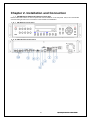
1-4 MX-SDI Series Name and Features of each part
MX-SDI series has buttons on the front panel and various interfaces on the rear panel. Also, it has rack handles
of the left and right side for the convenience of the standard rack installation.
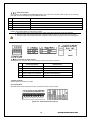
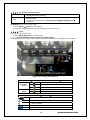
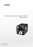
1-4-1 MX-SDI Series Front Panel
1-4-2 MX4-SDI Channel Rear Panel
8
Operating Instruction & User’s Guide
No.
1
2
3
Name
DC-IN Power
CONFIGURE
RS485
DIO
4
Ethernet
5
6
7
8
9
10
HDMI
eSATA
VGA-OUT
AUDIO OUT
AUDIO IN
CAMERA IN
Function
100~240V, 50/60 Hz, 5A
Select the type of video input and output
PTZ Camera Control Connection
Sensor/ Relay Connection
Network connection(ADSL, Cable Modem, Ethernet 10/100/1000
Base-T)
HDMI Video output
External SATA Storage
VGA Monitor or LCD Monitor connection
Audio output connection (Line Only Output)
Audio input connection (Line Only Input)
HD-SDI Camera connection
Type
Switch
Termnal Block
RJ-45
HDMI type-C
eSATA
D-SUB 15P
RCA
RCA
BNC
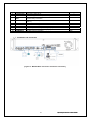
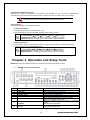
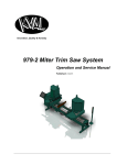
1-5 Installation and Connection
[Figure 2-1. MX4-SDI Basic Connection and Device Connection]
9
Operating Instruction & User’s Guide
1-5-1 Basic Connection
By referring to above [Figure 2-1] and [Figure 2-2], Connect the CCTV camera, HDMi monitor (or VGA monitor),
and USB mouse to the DVR and set up CONFIG SWITCH.
Connecting Device
DVR Terminal
1
CCTV camera
Rear Panel Video Input
2
VGA Monitor / LCD Monitor
Rear Panel VGA-OUT
3
Mouse
MX-SDI series: on front panel
4
CONFIG SWITCH
Rear Panel NTSC/PAL or VGA/TV Setup
Refer to the CONFIG SWITCH description as below.
1. The input video type must be either NTSC or PAL; these two types must not be used together.
2. Select the input video format (NTSC/PAL) using the CONFIG switch on the rear side of the product.
3. Select the input video resolution between 1080p and 720p. These two types must not be used together.
1-5-2 Connection of Other Devices
Connect the PTZ controller cable, audio in/output, network and sensors as below.
Connecting Device
DVR Terminal
1
Mike / Speaker
Rear Panel Audio Input / Audio Output
2
LAN Cable
Rear Panel Ethernet
3
PTZ Camera
Rear Panel Terminal Block
4
Sensor / Relay / TTL OUTPUT
Rear Panel Terminal Block)
5
Key controller
Rear Panel Terminal Block
1) Audio In/Output
Audio supports 4 inputs and 1 output.
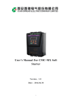
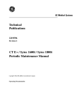
2) Terminal Block
Terminal Block on the rear panel is for the connections of PTZ / Sensor / Relay.
[Figure 2-2. Terminal Block Description]
10
Operating Instruction & User’s Guide
4) PTZ Camera/Keyboard Controller
Connect PTZ camera to TRX+(No.4) and TRX-(No.5) and GND(No.10). You may refer to APPENDIX for
supported PTZ camera list in this manual. Keyboard Controller has same connection way of PTZ camera.
PTZ Camera may not be working properly if GND is not connected.
5) Sensor/Relay
Connect Sensor/Relay to Terminal Block directly.
(1) Sensor Connection
① Connect Sensors to the Terminal Block S1 ~ S4.
② Each input terminal may be connected regardless of the channel number.
Sensor has the type of NC(Normal Close) and NO(Normal Open).
For Setup {Menu} {Setup} {Action} {Event} {Sensor Type}
NC(Normal Close) : Normally closed; opens when a signal is received.
NO(Normal Open) : Normally opened: closed when a signal is received.
(2) Relay Connection
① Outputs alarm signals to external devices such as siren by relaying them to these external devices.
② Connect Relay to R1 of Terminal Block (TB1).
Relay has the type of NC(Normal Close) and NO(Normal Open).
For Setup {Menu} {Setup} {Action} {Alarm} {Relay Type}
NC(Normal Close) : Normally closed; opens when a signal is received.
NO(Normal Open) : Normally opened: closed when a signal is received.
Chapter 3. Operation and Setup Tools
MX-SDI series are conveniently operated by Front Buttons, Remote Controller and mouse.
1-6 MX-SDI series Front Panel Button
No.
1
2
3
4
5
Name
LABEL
RECORD
USB
Number (0~9)
ODD
6
Reverse Play / Fast Reverse RELAY
7
Reverse Frame by Frame or TAB
STATUS
8
PAUSE
LOCK
11
Feature
Brand Name and Model Name
Recording start/stop for all channels
USB Mouse or Memory USB Stick
System Login or Number input
CD-RW, DVD-RW
Backward Playback/Rewind (in Playback mode)
Relay Control (in Monitoring mode)
Backward Playback Frame by Frame (in Playback
mode)
View System Configuration
Pause (in Playback mode)
Lock (in Monitoring mode)
Operating Instruction & User’s Guide
9
10
11
12
13
14/15
16
17
18
19
Forward Frame by Frame or TAB
LOG
Forward Play / Fast Forward
PLAY
COPY
PTZ
SEARCH
UP/DOWN
ESC
MENU
RECORD LED
NETWORK LED
20
ALARM LED
21
ERROR LED
22
23
23
24
POWER LED
SELECT
MOVE & DISPLAY
IR Sensor
25
USB port
26
POWER
Playback Frame by Frame (in Playback mode)
System Log View(in Monitoring mode)
Playback/Fast Forward (in Playback mode)
Play back (in Monitoring mode)
Copy recording data
Change Pan/Tilt/Zoom mode
Search recording data
Speed control
Exit the current menu or selects the upper menu.
Various Modes
Green LED turned on upon HDD operation
Green LED turned ON during remote access
Red LED turned on upon the occurrence of event or
motion.
Red LED turned on upon fan defect or recording
interruption.
Power LED On/Off
Select the menu or sequence
Select the menu or change the display mode
Remote controller input sensor
Connection port to the USB mouse and USB memory
stick
Turn the system power ON or OFF
12
Operating Instruction & User’s Guide
1-6-1 MX-SDI series Remote Controller
a)
b)
Basic Control Button
POWER
Turn the system power
ON or OFF.
ESC
Exit the current menu
or select the upper menu
MENU
To see the Menu
MODE
None usable
SELECT
Select the category or
automatic screen conversion
MOVE
Move from one category to another or
change the display mode
execute
Search Button (Playback Mode)
Reverse Play
Reverse Play
Play
Play
Reverse Frame by Frame
Reverse play frame by frame
Pause
Pause
Frame by Frame
Play frame by frame
1-6-2 Mouse
Operate the system by using Mouse. The mouse pointer will be shown when a Mouse is connected to USB port
on the front panel.
Mouse control supports the features as below.
Click on the right button
Click on the left button
Double click on the left
button
Drag the left button
Monitoring Mode / Move from Play Mode to
Monitoring Menu / Pop up or remove Play Menu.
Show sub-folder of the certain Menu window.
Select Menu.
Select Menu.
Move a certain window.
Chapter 4. DVR Operation Setup
13
Operating Instruction & User’s Guide
1-7 MX-SDI Series Storage Installation
※The recommended HDD specification are shown below.
Type
Size
Capacity
Buffer
RPM
SATA I, II
3.5“ 1, 2 Flat
Max. 2TB
Over 8MB
Over 7200
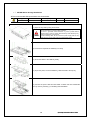
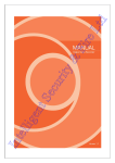
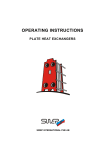
1) Open the top case by using screw driver.
1) Normal termination of the system and fully unplugged power code
are required before conducting HDD installation.
2) Touch a grounded metal substance or ground yourself before
installing HDD in order to reduce static electricity. Static electricity may
cause a malfunction of the product.
3) After installing HDD, Do not connect to power supply with the top
case opened. The top case must be covered before usage.
2) Unscrew and separate the HDD bay from body.
3) Screw the HDDs to the HDD bay hardly.
4) As per the photo, Screw the HDD bay, HDD and DVD to the top bay.
5) Connect the power cable and data cable on HDDs and then reassemble
the top case by reversing 1) to finalizing HDD installation.
14
Operating Instruction & User’s Guide
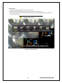
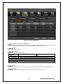
1-8Power ON.
① Check the adapter (12VDC/5A) and connect the power.
② Booting will be initialized after pressing the power button on the front panel.
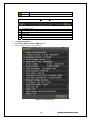
③ Menu widow pops up by clicking the right button of the mouse or pressing [MENU] button in the front
panel as shown below.
Default ID and PW is as below
[ ID: Admin, PW: 1111111 ]
[Figure 4-3. Menu Window]
15
Operating Instruction & User’s Guide
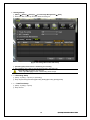
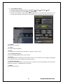
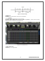
1-9Storage Setup
① {Menu} {Setup} {Storage} {Local Storage Management} {New}
② Select the HDD on New tap and then select Recording-Init.
[Figure 4-4. Storage Device New Tab menu]
③ {Recording-Init} means that it is initializing for recording.
④ After initializing done, HDD on New tab will be moved to Recording tab.
{Recording-Init} procedure may take time.
Refer to [6-4 Storage] for better understanding about storage.
1-10Recording Setup
① {Menu} {Setup} {Action} {Recording}
② Setup for [Recording Resolution]/[Recording Quality]/[Recording Speed]/[Audio].
1-11 Date/Time Setup
① {Menu} {Setup} {Time}
② Setup for time
16
Operating Instruction & User’s Guide
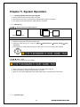
Chapter 5. System Operation
1-12 Starting System and Exiting the System
① Press the power button with the power connected.
② All channels connected to cameras will be displayed after booting is completed.
③ The system will be terminated after authentication is completed,
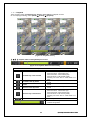
1-13 Monitoring
1-13-1 Screen Division and Auto Sequence
Full Screen(8 groups)
Use the Full Screen mode button or double click the channel you want
Auto Sequence
① Rotating images (channels) with the certain time.
② Select the certain time (1 sec.~10 sec.) on {Menu} {Miscellaneous} {display setting} {main
sequence}
③ Auto sequence is starting after pressing the select button or icons on the status bar as below.
1-13-2 Zoom (x16)
Zoom in & out for specific zone on live display.
① Move to the Zoom mode by selecting the icon on the status bar thru Mouse.
② Control the Zoom by using the up/down buttons or Mouse.
③ Menu for zoom will be disappeared after pressing ESC button or the left button of the Mouse.
1-14 System Login
17
Operating Instruction & User’s Guide
1-14-1 User Account and Authorization
The local administrator has all authorities. (But, remote access is not available)
Default password is [1111111]
Up to 15 users are allowed. Each user can access the functions depending on the
given authorities.
For Authorization Setup, Move to {Monitoring Menu} {Setup} {System}
{4. User }.
admin
User
1-14-2Login
For security purpose, user must log in first.
① Select {Menu} {Login} on the live display.
② Password for English can be shown after selecting the space of password.
1-14-3 Logout
After logout, user can’t use menu.
① Select {Menu} {Logout} on the live display.
1-15 System Information View and Display Setup Change
Audio/Recording Status/Channel Title/Connection Indicator/Time/HDD status are displayed as shown below.
[Figure 5-5. Recording Status Window]
※Recording Event / Recording mode display ※
Motion recording
Recording
Event
Sensor recording
Audio recording
Recording
Mode
Video recording
Audio recording
※Live Display ※
Video is not connected or Video is covert
Audio is set activated
Audio is set silent
No Signal
Camera has been disconnected
The channel for PTZ setup
18
Operating Instruction & User’s Guide
The channel for PTZ tour1 setup
The channel for PTZ tour2 setup
※Control Bar※
1Ch display mode
4Ch display mode
Auto Sequence
Date / Time
HDD Status
Playback
1-16 System Information
① Select {Menu} {Miscellaneous} {DVR info.}
② DVR info. Will be displayed as shown below.
[Figure 5-6. DVR Infomation]
19
Operating Instruction & User’s Guide
1-17 Display Setup
① Select {Menu} {Miscellaneous} {Display Setup}
(1) Camera Title, Control Bar, Button Sound
Set the title of camera and control bar, button sound.
(2) Border Line
Set the border line between channels.
(3) Screen Saver
Set Monitor saver.
(4) Main Sequence
Set the Duration for main, and on/off for event.
20
Operating Instruction & User’s Guide
1-18 Audio, Relay
① Select {Menu} {Miscellaneous} {Misc Control}
(1) Audio
Setup for Audio channel and mute.
(2) Relay
Setup for Reply out or cancellation
1-19 Search
Calendar Search
Search the recording data by year/month/day/time.
Go To The Last
Playback the last recorded data by multi-channel mode.
Go To The First
Playback the first recorded data by multi-channel mode.
Go To the Last Played Time
Playback the last played time by multi-channel mode.
21
Operating Instruction & User’s Guide
1-19-1 Calendar Search
Select {Menu} {Search} {Calendar Search} on the live display mode and then a searching window pops
up as shown below.
[Figure5-7. Search Window]
Green
Continues recording is in progress
Red
Motion recording is in progress
Blue
Sensor recording is in progress
Yellow
Audio recording is in progress
1-19-2 Time Index
① New folders (directories) are created every time when the time is changed on {Menu} {Setup} {Time}
{Date/Time}.
② Many Time Indexes comes out when you select the menu for Time Index on the right side of search mode.
Current
Old_Number
Recorded image files with the current set time.
Recorded image files before the time change.
1-19-3 List All
Current recording time list is showed regardless how many times system time has been changed.
① All list comes out after selecting {List All} on the bottom of search mode.
22
Operating Instruction & User’s Guide
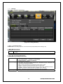
1-20 Log Viewer
DVR records all Log information over the system operation including Power on/off, System Setup and Network
Access. Move to {Menu} {Miscellaneous} {Log Viewer} to see the logs.
[Figure 5-8. Log Viewer]
All
Fail
Network
Recording Event
General
Logs related to all system operations.
Logs related to system operation failures, e.g., signal loss and network
connection failure.
Logs related to network operations e.g., network login, network logout,
and network live.
Logs related to recording, e.g., motion detection and sensor detection,
Audio detection.
Logs related to power ON/OFF, file copy/backup failure, setup start/end,
playback, and other basic system operations.
23
Operating Instruction & User’s Guide
1-21 Playback
There are three routes {Live Monitoring}, {Search}, {Log Viewer} to playback on DVR.
On Live display(monitoring), select {Menu} {Search} {playback}.
[Figure 5-9. Playback Screen]
1-21-1 Playback status and Playback Speed Control
[Figure 5-10. Playback Status and Control bar]
Button
Description of the Search Buttons
Name
Features
Press one time - Playback forward (x2)
Press two times - Fast forward (x4)
Press four times - Fast forward (x16)
Forward Play / Fast Forward
Press six times - Fast forward (x300)
Pressing one more time in x300 leads to x1
back.
Playback frame-by-frame
Forward Frame by Frame
Pause
Pause
Pause
Reverse Frame by Frame
Reverse Play / Fast Reverse
ESC
Reverse playback frame by frame
Pause
Press one time - Playback reverse (x1)
Press two times - Fast reverse (x4)
Press four times - Fast reverse (x16)
Press six times - Fast reverse (x300)
Pressing one more time in x300 leads to x1
back.
Exit to Playback Mode.
Status bar indicating information of the hourly
recorded image data
24
Operating Instruction & User’s Guide
1-21-2 Smart Search
This function is for search an image with the object movement at a specific zone as fast as it can. Searching by
each channel is available.
1-21-3 MULTI TIME
Multi-Time is to play the recorded image of the different time over a certain designated channel. The lineup of the
recorded image of the different time is the most recent-bottom.
1-21-4 MULTI DAY
Multi-Day is to play the recorded image of the different day over a certain designated channel.
The lineup of the recorded image of the different time is the most recent-bottom.
1-21-5 Event
Event is to play the recorded image with [All/Motion/Sensor/Audio].
1-21-6 Panorama Playback
Playback the certain channel by frame by frame..
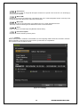
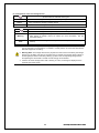
1-22 Backup
Before backup process, CD/DVD or external HDD, CD, DVD supporting USB2.0 should be connected to the DVR.
Refer to Appendix on the last page of this manual to get information of compatible list.
There are three routes to backup on DVR.
[Figure 5-11. Backup]
25
Operating Instruction & User’s Guide
① In real-time monitoring mode, select {Menu} {Backup} {Backup}. The backup menus will then
appear.
② Show the free and total space, after selecting backup device.
③ Check the time/date and channel.
④ Backup will be progressing after click the start button.
If the total size is smaller than backup size, it shows as red and not allowed to backup.
If the backup storage device is not formatted, in case the box displaying the size of the
file to be backed up is displayed in yellow, and if backup is executed by pressing the
Copy (Backup) button, a prompt asking whether to erase the device will appear as
shown below. Selecting [YES] causes the storage medium for the selected device to be
erased.
1-23 Snapshot
The Snapshot function lets the user create a JPG file in live monitoring, playback.
On the live monitoring, Select {Menu} {Backup} {Capture} and then directly move to Shapshot
menu.
① Will see the storage selection window. After selecting storage, backup will be done.
1-24 Log Backup
All of recorded log data such as Normal/ Recording Event/ Network/ Failure could be backed up.
① Select {Log Viewer} {Log Backup} or {Menu} {Backup} {Log Backup}.
② Setup after checking device, time and event. .
③ Backup is started after selecting start button.
Log file is text format so the file could be open easily.
1-25 Setup Backup
Backup all setup data which is applied to the DVR.
① Select {Menu} {Backup} {Setup Backup}.
② After selecting storage, backup will be done.
③ The file from Setup Backup can be applied to another DVR with {Menu} {Setup} {System}
{Upgrade} {setup}.
26
Operating Instruction & User’s Guide
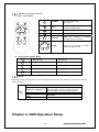
1-26 PTZ Camera Control
① PTZ camera setup should be correct on here {Menu} {Setup} {Definition} {PTZ}.
② In real-time monitoring mode, select {Menu} {PTZ Control}.
③ PTZ Full control window is coming out after selecting MENU button or the right button of the Mouse. If you
are okay with PTZ Simple control window, selecting ESC button or the right of the Mouse just after that.
<PTZ Simple Control Window>
(1) Camera
Select PTZ to be controlled.
<PTZ Full Control Window>
(2) Speed
PTZ camera speed is adjustable.
(3) Tour
To use this feature, it should be setup with {Menu} {Setup} {PTZ} {Tour}.
(4) Left,right/up,down/zoom
Control the Left/Right/Up/Down/Zoom of PTZ camera.
(5) Preset
Using Leftl/Rightl/Zoom movement of PTZ Camera, zoom or focus a certain spot of the image by designating
the coordinates and move to the designated coordinates quickly.
(6) Home Position Time
If there are no controlling signals to PTZ camera after a certain time, it goes automatically to the Preset No.1
position as Preset No. 1 is designated as Home Position.
(7) Menu
Control PTZ Menu directly.
27
Operating Instruction & User’s Guide
Chapter 6. Setup
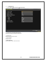
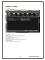
1-27 Time
Select {Menu} {Setup} {Time} on the live display(Monitoring).
[Figure 6-12. Date and Time Window]
(1) NTP Sync
Synchronize DVR time with NTP Server time at one time in hour.
(2) Date and Time
Change the system date/time and the time format.
(3) Standard Time Zone
Select {Standard Time Zone}, {Daylight Saving Time}, {Start/End time}.
(4) Auto Rebooting
Select the period for auto rebooting of DVR system.
28
Operating Instruction & User’s Guide
1-28Definition
Select {Menu} {Setup} {Definition} on live display (Monitoring).
[Figure 6-13. Definition Window]
1-28-1Camera
(1) Connect
Set on/off of the camera.
(2) Title
Set the name of each camera up to 20 characters.
(3) Covert
Set the live channel not to be showen.
※On the live display(Monitoring), it shows as black. But, it keeps recording as setup.
1-28-2 PTZ
Set the Tour, Protocol, ID, Baudrate of PTZ camera.
1-28-3 Event Source
Set the Motion Area, Motion Sensitivity, Sensor Type, Sound Sensitivity.
1-28-4 Relay
Set the type of Relay.
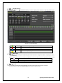
1-29 Recording
Set recording, system, main features. {menu} {setup} {Recording}
29
Operating Instruction & User’s Guide
[Figure 6-14. Recording Window]
1-29-1 schedule (schedule1 - schedule4)
4 different settings can be applied by time and date on schedule table for user convenience. Please go to
menu/schedule after setting up schedule1, schedule2, schedule 3, schedule 4 differently.
1-29-2 Event
Set the motion, Sensor, Audio.
1-29-3 Recording
Set the Resolution, Frame, Quality, Audio.
Resolution
720p
1080p
Normal Speed
Event Speed
NTSC recording resolution
PAL recording resolution
1280 x 720
1920 x 1080
Recording frame rate
when record continuously
When record by motion, sensor, audio
1-29-4 Alarm
Set the Alarm action Buzzer, PTZ Preset, E-mail, Relay, Spot, Popup and Callback when event comes out.
1-29-5 Duration
Pre alarm( On / OFF ), post alarm(5sec / 10sec / 15sec / 20sec / 60sec / 150sec / 300sec)
30
Operating Instruction & User’s Guide
[Figure 6-15. Pre/post alarm]
1-29-6 Log
Set On/off of log by motion detection / sensor input / sound detection.
1-30 Schedule
Select {Menu} {Setup} {Schedule} on the live display.
{Schedule} is used to save the system configuration as data from {Schedule 1 ~ 4} and to make a recording
based on the system configuration for each day/time zone.
[Figure 6-16. Schedule Window]
1-30-1Holiday setup
Set the Holiday for recording schedule.
31
Operating Instruction & User’s Guide
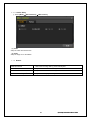
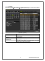
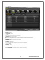
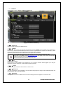
1-31 Storage
Select {Menu} {Setup} {Storage}.
[Figure 6-17. Storage Window]
1-31-1 Private Recording
This is to limit the recording days. You can set None/1day/7days/30days/User setting (1-99).
1-31-2 HDD Overwrite
Set On/Off for HDD Overwrite.
If there is no more hard disk space left, the existing files will be overwritten starting with the
On
oldest.
Off
If there is no more hard disk space left, further recording will not be executed.
1-31-3 Local Storage Management
(1) Local Storage Management Function
New
Recording
Backup
All initially detected storages are displayed as New
Recording Initialize – Changed it for Recording
Backup Initialize – change it for Backup
Storage list for Recording
※ At least, one storage shall be selected as a dedicated storage. Otherwise, the
data cannot be stored in real time.
New – Returns the status of the selected storage device to New
Online - Changes the selected storage device in online state.
Offline - Changes the selected storage device in offline state. (Disable to record)
Format – Format the selected storage. (Available only in Offline.)
Eject - Separates the selected device completely from the software.
Storage list for Backup
32
Operating Instruction & User’s Guide
(2) Configuration of the local storage device
※There are three software status types.
Active
Connected to storage or backup device; currently saving the data.
Online
Only connected to storage or backup device.
Offline
Not connected to storage or backup device.
※There are three hardware status types.
Healthy
Connected to storage or backup device; functions normally.
Warning
Connected to storage or backup device, but error was detected; in this case,
data storing or backup cannot be made (for more information, see the
description below).
Fault
Not connected to storage or backup device; cannot perform data saving or
backup.
1. Fault State: The storage device is completely damaged, and none of the S/W operations
can be performed. The fault state is not related to a DVR problem. The DVR has detected the
fault and stopped the recording.
2. Warning State: The storage device has a physical error that can be corrected by the storage
device or by the DVR. If the error is not taken care of, however, the storage device is likely to
be damaged (and shift to fault state). Backing up data in the corresponding storage device
and replacing the device with a normal one are strongly recommended.
3. If there is an active storage device with a warning or a fault, a message is displayed on the
upper left part of the screen.
33
Operating Instruction & User’s Guide
1-32 Network
Set the system network. {Menu} {Setup} {Network}.
[Figure 6-18. Ethernet Window]
1-32-1 Ethernet
Set the IP, ADSL, Gateway and DNS as above.
1-32-2 DDNS
As part of the DNS system, the Dynamic Domain Name System (DDNS) service updates the IP addresses of
host names in real time and allocates fixed domain names to systems linked to dynamic IP addresses to allow
users to use the same DNS name regardless of the changes in the IP address.
It provides dynamic DNS to ensure URL access in the dynamic IP environment.
User can monitor the remote place thru internet with web server functions which is equipped in DVR.
※ Access to DynDDNS sever(http://www.dyndns.org) and apply for the user account then,
register the domain name to use and enter URL.
※ For more information, please access to the sever.
1-32-3Port
Set the port for network.
UPnP function will be available on the selection of On. On UPnP, ’Success’ will be popped up on the port
registration at Router. Otherwise, ‘Failure’ will be popped up instead.
1-32-4 E-mail
Automatic E-mail transmission service when an event occurs.
1-32-5 Bandwidth
This sets up the limit of the bandwidth to be used when bringing the live image, adjust resolution/quality and
transmitting the data by using the network.
1-32-6 Callback
The signal is transferred to callback server for auto-recording when there happens an event at the site.
34
Operating Instruction & User’s Guide
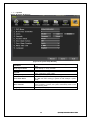
1-33 System
{Menu} {Setup} {System}
[Figure 6-19. System Setup Window]
DVR Name
Set to the MAC address for DVR. Available to change whatever user
wants.
ID for Key Controller
Set the identify no. of key controller
Users
Adds, edits, or deletes the users who will operate the system.
Firmware – Firmware upgrade
Setup – Change the setup of DVR
Initializing it as setup (Except Network setup)
Alarm is to notify system incidents [Video Signal loss/ HDD full/ FAN
fail/ HDD fail/ HDD warning] to [Alarm/ E-mail/ Relay01/ System
check].
Set the alarm duration
If no input is made in the System Setup menu using the front buttons,
remote controller, or mouse, the system automatically shifts to realtime monitoring mode.
Set the system language.
Upgrade
Factory Setup
Error Alarm Action
Error Alarm Duration
Menu Time Out
Language
35
Operating Instruction & User’s Guide
APPENDIX
APPENDIX
(1) Recommended HDD
Type
Size
Capacity
Buffer
RPM
SATA I, II
3.5“ 1, 2 Flat
Max. 2TB
Over 8MB
Over 7200
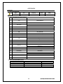
(2) Recommended PTZ Camera Protocol.
Vendor
NO
1
A.D.
2
CHOU
Protocol
SENSORMATIC
COHU
3
Dongyang
4
DYNACOLOR
DRX-500
DY-255
DSCP
5
EYE VIEW
EYE VIEW
6
FINE SYSTEM
CRR-1600i/s
7
GE
GE_KARATEL
8
GSP
CYBERSCAN_1
9
HITRON
FASTRAX2
10
HONEYWELL
HSDN-251
11
LG
12
MIKAMI
LG_MULTIX,
LG_OLD
MIKAMI
13
ORIENTAL
ORX-1000
14
PANASONIC
WVCS854
15
PELCO
16
PHILIPS
PELCO – D
PELCO - P
PHILIPS
17
PROLINE
PROLINE_UK
18
RIFATRON
RIFATRON
19
SAMSUNG TECHWIN
20
SUNJIN
SPD-1600
SCC641
SUNJIN
21
VICON
VICON
22
YOKO
YOKO
(3) Recommended USB2.0 Device
USB2.0 Device
Memory Stick
2.5’’ Portable USB HDD
CD
DVD
Media
Flash Type
HDD Type
CD R, R/W
DVD +R, +R/W
36
File System
FAT32
FAT32
ISO9660
ISO9660
Operating Instruction & User’s Guide