1
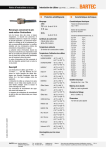
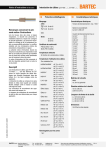
Operating Instructions
Position Switch type 07-2931-1 ***/**
Position switch without actuator
Explosion protection
Technical data
Ex protection type
II 2G Ex d IIC T6
II 2D Ex tD A21 IP66 T80 °C
0044
Weight
depends on the model
Tightening torque
Actuator screws 0.9 Nm
Certification
PTB 09 ATEX 1048 X
Ambient temperature
Operation:
Storage, transport:
Actuator
Further technical information
Types of contact, contact assignments and
switching examples: see page 5
-20 °C to +60 °C
-20 °C to +80 °C
Approved for zones
1/21 and 2/22
Cable entry
Description
Technical data
Position switches are used wherever movable
parts on machinery and systems have to be
positioned, controlled and monitored. They
control and facilitate signal transmission in
switching gear or function as switches in regulating and control devices.
The flameproof encapsulated BARTEC position
switches can be used in hazardous (potentially
explosive areas in Zones 1 and 2 in accordance with the certified explosion subgroups
IIA, IIB and IIC and the temperature class T6
and in Zones 21 and 22 according to the
certified maximum surface temperature.
NOTE
See page 4 for the designations of the components in the position switch.
8
Dimensions in mm
Enclosure without actuators
1,5
60
ca. 103
30
5,5
ø 5,5
12,5
Protection class
IP 66 (IEC 60529)
Pressure screw
M 20 x 1.5
Weight
ca. 160 g
Cable diameter 5 to 8.4 mm
Washer:
Outside diameter 18.3 mm
Inside diameter 8.7 mm
Thickness 1 mm
Mechanical switching unit
Rated insulation voltage
400 V
Rated operating voltage/current
AC 15:400 V/4 A
AC 15: 24V and 240 V/6 A
DC 13: 24V/3 A
DC 13:110 V/0.8 A
DC 13:220 V/0.3 A
Rated impulse strength
4 kV AC
Switching rate
up to 6000/h depending on type
Service life
electrical: depending on load
mechanical: max. 106 switching cycles (depending on actuation angle/speed)
Electronic switching unit
Rated voltage
up to 30 V DC
Rated operating voltage/current
DC 12 V/0.015 A
DC 24V/0.018 A
DC 30 V/0.019 A
Sealing ring:
(fitted, without marking)
Outside diameter 18.5 mm
Inside diameter: 8.4 mm
Height: 13 mm
Cable diameter 8 to 12 mm
Washer:
Outside diameter 18.3 mm
Inside diameter of 12.2 mm
Thickness 1 mm
Sealing ring:
(with marking “20S”“)
Outside diameter 18.5 mm
Inside diameter of 11.7 mm
Height 13 mm
NOTE
For a picture of the cable entry see also the
assembly illustrations on page 4.
Tightening torques
Lid screws: max. 0.9 Nm
Pressure screw: 5 Nm
Enclosure /plunger material
Injection moulding made of thermoplastic
46,3
42,5
17
01-2930-7D0001-A.01-BARTECAdvertisingAgency-291427E
SW 24
Technical data
BARTEC GmbH Max-Eyth-Straße 16
D-97980 Bad Mergentheim
Tel.: +49 7931 597-0
Fax: +49 7931 597-119
[email protected]
www.bartec.de
Reservation Technical data subject to change without notice. Changes, errors and
misprints may not be used as a basis for any claim for damages.
1/7
Operating Instructions
Position Switch type 07-2931-1 ***/**
Safety Instructions
Marking
Incorrect installation can cause malfunctioning
and the loss of protection against explosions.
The position switch may be connected and
assembled only by qualified personnel who are
authorised and trained to assemble electrical
devices in hazardous (potentially explosive)
areas.
The position switch with actuation may never
be operated without the actuator. Only use
sealing rings and washers that suit the conductor diameter. Utilisation without a sealing ring /
washer or with an incorrect sealing ring /
washer will lead to the loss of protection class
and explosion -proofness. The fully installed
position switches must close tightly (observing
torques).
Do not open position switches if the atmosphere is explosive. Always disconnect the
actuator from voltage before assembly
/disassembly.
Utilisation in areas other than those specified or
the alteration of the product by anyone other
than the manufacturer will exempt BARTEC
from liability for defects or from any further
liability.
The generally applicable statutory rules and
other binding directives relating to workplace
safety, accident prevention and environmental
protection must be adhered to.
The position switch may be used only if it is
clean and free of any damage. The position
switch may not be used as a mechanical stop.
Particularly important points in these instructions are marked with a symbol:
DANGER
Non-observance leads to death or serious
physical injury. The necessary safety measures
must be implemented.
CAUTION
Warning of damage to property and financial
and penal disadvantages (e.g. loss of guarantee rights, liability claims etc.).
ATTENTION
Important instructions and information on
preventing disadvantageous behaviour.
NOTE
Important instructions and information on
effective, economical and environmentally
compatible handling.
Standards conformed to
01-2930-7D0001-A.01-BARTECAdvertisingAgency-291427E
EN 60079-0:2006
EN 60079-1:2007
EN 61241-0:2006
EN 61241-1:2004
EN 60947-5-1:2004
EN 61000-4-2:2001
EN 61000-4-3:2001
EN 61000-4-4:2002
EN 61000-4-5:2001
EN 61000-4-6:2001
Assembly and Commissioning
ATTENTION
Only authorised and qualified personnel may
do any of the assembly, disassembly, installation and commissioning work.
CAUTION
The relevant installation and operating regulations must be observed when setting up or
operating explosion-proof electric systems.
Assembly/Disassembly
ATTENTION
If the position switches / actuators are stored in
a cold environment, condensation may occur in
the site of installation. Only mount components
without condensation.
Dust deposits exceeding 5 mm must be removed.
At least two 5-mm-diameter screws must be
used for mounting the position switch.
A strain relief device (e.g. SILVYN-RKS cable
clamp from Lapp or equivalent) must be fitted
approx 50 mm after the screwed connection.
Observe the minimum bending radius for the
cable.
NOTE
The assembly steps are illustrated on page 4.
Installation
DANGER
The supply cable must be selected so that it
satisfies the thermal and mechanical requirements in the area of use. It is important not to
damage the core insulation during installation.
Only the conductors listed in the table on page
3 may be used.
When shielded conductors are used, the
sheathing must be cut off flush with the outer
jacket.
When connecting multi-wire or fine-stranded
conductors, prepare the conductor ends first.
Supply cable, cross-section:
0.75 - 2.5 mm2 (one-wire)
0.75 - 1.5 mm2 (fine-wired, wire end ferrule)
DANGER
Always use the sealing ring and washer included in the scope of supply that suit the
conductor diameter.
Only use parts included in the scope of supply.
Never use cable entries or parts from another
manufacturer.
The max. torque for the lid fixing screws is 0.9
Nm.
Commissioning
Before commissioning check that:
•
•
•
•
•
•
•
•
•
Switching point setting
CAUTION
Do not open position switches in an explosive
atmosphere.
The switching point in the electronic switching
unit can be set in the range from 0.5 mm to 5.5
mm:
•
•
•
•
•
BARTEC GmbH Max-Eyth-Straße 16
D-97980 Bad Mergentheim
Tel.: +49 7931 597-0
Fax: +49 7931 597-119
[email protected]
www.bartec.de
the device has been installed in compliance with regulations
the device is not damaged
there is no foreign matter in the device
the junction box is clean
the connection has been established
properly
the cable has been run in properly
all screws are tightened securely
the cable entry, sealing ring and sealings
have been fitted correctly
the flameproof enclosure is not damaged
Loosen the lid screws and take off the lid
Move the actuator to the switching position
Press the set button on the switching unit
for 1 s
LED must flash with a high frequency
Put on the lid, tighten the lid screws
Reservation Technical data subject to change without notice. Changes, errors and
misprints may not be used as a basis for any claim for damages.
2/7
Operating Instructions
Position Switch type 07-2931-1 ***/**
Operation
Fault clearance
Accessories, Spare Parts
DANGER
The position switch may be operated only
within the technical limits that apply to it (see
the Explosion Protection and Technical Data
sections).
DANGER
If the conductor to the position switch is replaced, a new sealing ring and a new washer
must be inserted too.
Always use a sealing ring and washer that suit
the conductor diameter.
The position switch is defective if the switching
unit does not perform the switching function or
the actuator does not activate the switching
unit any longer. Defective position switches
cannot be repaired; they must be replaced.
Only original parts (e.g. sealings, sealing rings,
washers, pressure screw) may be used as
replacements.
Defective actuators can be taken off the position switches and replaced by functioning
actuators of the same type.
DANGER
A new sealing must be inserted whenever the
actuator is replaced.
on request
Maintenance
The operator of the position switch must keep it
in an orderly condition, operate it correctly,
monitor it and clean it regularly. The enclosure,
sealings and cable entry must be checked
regularly for cracks and damage.
NOTE
Dirty enclosures/actuators can be cleaned with
dry and clean compressed air.
Disposal
The components in the position switch and the
actuator contain metal and plastic parts.
For that reason the statutory requirements for
electronic scrap must be adhered to when
disposing of them (e.g. disposal by an approved disposal company).
Service Address
BARTEC GmbH
Max-Eyth-Straße 16
D-97980 Bad Mergentheim
Tel.: +49 7931 597-0
Fax: +49 7931 597-119
Supply cables to be used
01-2930-7D0001-A.01-BARTECAdvertisingAgency-291427E
DANGER
Only the following supply cables may be used. Equivalent conductors (i.e. from other manufacturers) are permitted.
Cable
Max. ambient temperatur
Min. conductor cross-section
H07RN-F / A07RN-F
H05RN-F / A05RN-F
40 °C
40 °C
0.75 mm2
0.75 mm2
H05VV-F / A05VV-F
Ölflex® (shielded also)
40 °C
40 °C
0.75 mm2
0.75 mm2
Unitronic-LiyCY
40 °C
0.75 mm2
H05VV-F / A05VV-F
Ölflex® (shielded also)
60 °C
60 °C
1.5 mm2
1.5 mm2
NSSHöu
60 °C
1 mm2
Ozoflex plus H07RN-F
60 °C
1 mm2
H05GG-F
60 °C
1 mm2
Radox (shielded also)
60 °C
1 mm2
BARTEC GmbH Max-Eyth-Straße 16
D-97980 Bad Mergentheim
Tel.: +49 7931 597-0
Fax: +49 7931 597-119
[email protected]
www.bartec.de
Reservation Technical data subject to change without notice. Changes, errors and
misprints may not be used as a basis for any claim for damages.
3/7
Operating Instructions
Position Switch type 07-2931-1 ***/**
Components in the Position Switch
1
2
4
1
2
3
4
5
6
7
8
9
3
9
8
7
Lid
Switching unit
Lid sealing
Sealing on the actuator side
Actuator with screws (example)
Enclosure
Sealing ring
Washer
Pressure screw
5
6
Assembly
1
3
2
6 mm
40 mm
4x
*)
4
5
max. 0,9 Nm
01-2930-7D0001-A.01-BARTECAdvertisingAgency-291427E
4x
**)
Explanations
*)
The sealing ring for large conductor diameters is marked “20S”.
**)
Only when changing or turning the actuator. Adjustment and insertion depend on the actuator being used.
BARTEC GmbH Max-Eyth-Straße 16
D-97980 Bad Mergentheim
Tel.: +49 7931 597-0
Fax: +49 7931 597-119
[email protected]
www.bartec.de
Reservation Technical data subject to change without notice. Changes, errors and
misprints may not be used as a basis for any claim for damages.
4/7
Operating Instructions
Position Switch type 07-2931-1 ***/**
Types of Contact, Contact Assignments and Switching Examples
Type 07-2931-1122/**
Type 07-2931-1166/**
Type 07-2931-1126/**
Type 07-2931-1226/**
13
23
11
21
13
21
13
21
15
27
14
24
12
22
14
22
14
22
16
28
2 Positive opening operation
contacts
Slow-action contact element
2 N/O contacts
Slow-action contact element
1 N/O contact / 1 positive open- 1 N/O contact / 1 positive open- 1 N/O contact / 1 positive opening operation contact
ing operation contact
ing operation contact
Slow-action contact element
Snap-action contact element Overlapping slow-action contact
element
Type 07-2931-1421/**
Type 07-2931-1411/**
+Ue
+Ue
elektron.
elektron.
Q1
Type 07-2931-1326/**
Q1
Q2
Q2
0V
0V
1 N/O contact / 1 N/C contact
Operating position electronically adjustable
2 N/C contacts
Operating position electronically adjustable
Type 07-2931-1500/**
Type 07-2931-1600/**
U (V)
I (mA)
10
20
4
0
S (%)
100
0
S (%)
100
analog electronic position switch 4 - 20 mA
analog electronic position switch 0 - 10 V
Switching example for 07-2931-1500/**
Switching example for 07-2931-1600/**
+24 V (-15 / +20 %)
+24 V (-15 / +20 %)
+Ue
£ 200 mA
+Q2
4 - 20 mA
+Q1
0V
£ 10 mA
+Q1
0V
A
R < 400 W
01-2930-7D0001-A.01-BARTECAdvertisingAgency-291427E
+Ue
£ 200 mA
+Q2
K1
» Ue
V
» Ue
0 V - 10 V
K1
0V
0V
Explanations
The diagram labelling is identical to the connection labelling in the position switch.
BARTEC GmbH Max-Eyth-Straße 16
D-97980 Bad Mergentheim
Tel.: +49 7931 597-0
Fax: +49 7931 597-119
[email protected]
www.bartec.de
Reservation Technical data subject to change without notice. Changes, errors and
misprints may not be used as a basis for any claim for damages.
5/7
Operating Instructions
Position Switch type 07-2931-1 ***/**
LED Mode of Operation
A lamp tube for the LED display for the switching unit (A) is fitted into the lid. This display shows the operating status of the switching unit.
A
Types 07-2931-1411/** and 07-2931-1421/**
The electronic position switches have a self-test function. The Q1 and Q2 outputs are constantly monitored for overload, short circuit against 0 V and short circuit
against +Ue. The LED display in the lid indicates the operating status as well as the plunger actuation and set button:
Plunger not actuated
Plunger actuated
Set button actuated,
new operating position accepted
Fault in the device
1x
2x
3x
Types 07-2931-1500/** and 07-2931-1600/**
The electronic position switches have a self-test function. The Q1 and Q2 outputs are constantly monitored for overload, short circuit against 0 V and short circuit
against +Ue. The LED display in the lid indicates the operating status:
Type 07-2931-1600/**
Normal case:
Q1 = 0 - 10 V
Q2 ≈ Ue
Fault:
Q1 = 0 mA
Q2 = 0 V
Fault:
Q1 = 0 V
Q2 = 0 V
01-2930-7D0001-A.01-BARTECAdvertisingAgency-291427E
Type 07-2931-1500/**
Normal case:
Q1 = 4 - 20 mA
Q2 ≈ Ue
BARTEC GmbH Max-Eyth-Straße 16
D-97980 Bad Mergentheim
Tel.: +49 7931 597-0
Fax: +49 7931 597-119
[email protected]
www.bartec.de
Reservation Technical data subject to change without notice. Changes, errors and
misprints may not be used as a basis for any claim for damages.
6/7
Operating Instructions
BARTEC GmbH Max-Eyth-Straße 16
D-97980 Bad Mergentheim
Position Switch type 07-2931-1 ***/**
Tel.: +49 7931 597-0
Fax: +49 7931 597-119
[email protected]
www.bartec.de
Reservation Technical data subject to change without notice. Changes, errors and
misprints may not be used as a basis for any claim for damages.
7/7