1
Installation and Operating Instructions
0158
0093.102.00 b
Lumiglas luminaire 'Lumiflex' USL 07 ALF-Ex
II 2G Ex de IIC T6/T4 Gb
II 2D Ex tb IIIC T80°C/T130°C Db
•Important, please note:
This Lumiglas Ex light guide luminaire can be used as a sight glass luminaire or for illuminating individual objects, e.g. on machine tools. Ex-classified luminaires with light guide are also intended for observing processes in reactors, plants, vessels, etc., wherever the use of standard Ex luminaires is
not possible due to space restrictions. Under no circum-
stances should a sight glass luminaire be utilised to replace the cover flange or the complete sight glass flange fitting or used on its own to cover a container port. Luminaires for potentially explosive areas must always be installed,
connected and serviced by persons who have been specially trained and authorised to do this work.
•General operating conditions:
-Independent of internal pressure/vacuum in the vessel when used as a sight glass luminaire
-Approved for use in Ex-hazardous environments:
Gas: Zones 1 and 2; Dust: Zones 21 and 22
Also suitable for illumination purposes in Zone 0 and
Zone 20 together with a sight glass.
-The specified temperatures and installation position must be observed to ensure faultless operation
-
Approved for applications at ambient temperatures of
between -20°C and +40°C (or up to +60°C)
-Temperature-resistance of light guide: -20°C to +150°C
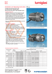
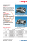
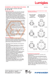
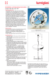
Lumiglas Ex luminaire with light guide 'Lumiflex’ USL 07 ALF-Ex
•Changing the lamp:
-Disconnect the luminaire from the mains supply and ob serve the waiting time specified on the type plate.
-To change the lamp, loosen the light guide (2) from its
holder on the screwed sight glass (1.4) and pull it out.
-The light guide and the receptacle hole must be treated with care and protected against damage (important to the Ex protection function). Keep the screws in a safe place!
-Loosen the locking screw (1.2) for the screwed sight glass (1.4); this will release the locking plate (1.3).
-The screwed glass lens should only be loosened and
dismantled using the special claw spanner (6805.002.00).
-In the open bulb compartment, loosen the retaining screw (c) of the bulb holder and swivel it upwards; undo the wires to the lamp at the terminal (f).
-Pull the bulb (e) past the retaining screw and remove it.
-Carefully insert the new bulb, following the instructions on the enclosed leaflet.
-Re-attach the wires to the terminal.
-Swivel the bulb holder with bulb back into place and
•Electrical connection:
-The connecting cable used must be capable of withstanding secure with the retaining screw.
-Screw the glass lens back onto the housing until it is tight an operating temperature of between -20°C and at least
again (pressure against O-ring).
+ 95°C, such as Sinotherm 110 H05GG-F 3G 1.5 mm².
-The locking plate must engage in one of the notches to -Open the cover of the terminal box on the light gene ensure the screwed sight glass is locked.
rator (1).
-Tighten the locking screw again. Carefully position the -Loosen the cable relief screws (with anti-rotation tabs) of light guide in the slot again and screw it against the O-ring the cable entry gland (1.7).
until it is tight.
-Insert the cable with the connecting cords through the
-Once the luminaire has been properly mounted, it is ready Ex e cable gland M20 x 1.5 (1.7) into the terminal compart-
for operation.
ment. Then tighten the screws again.
-Connect to Ex terminal (1.6).
-Connect the protective ground wire to the internal protec tive ground terminal (1.5).
-Connect the external protective conductor terminal (1.1) to a separate operational earth.
-Place the cover seal in position.
-Close the cover and screw it tight.
-The connecting cable should be tied at a max. distance of
1 m from the light generator and fixed in place.
•Electrical data – general
-The voltage, output, temperature class and type of
protection are specified on the type plate
-Lamp wattage: 20 W/39 W
-IP65 and IP67 acc. to EN 60529/DIN VDE 0470 Part 1
-Ex approval acc. to EC type examination certificate:
BVS 10 ATEX E 100 X
II 2G Ex de IIC T6/T4 Gb
II 2D Ex tb IIIC T80°C/T130°C Db
-The 20 W transformer variant is PTC protected. The 39 W
version is fused using a 315 mA fusible cut-out acc. to
IEC 60127-2/3. Do not change the fuse until the appliance has been disconnected from the mains.
-It is essential to comply with the data in the EC type exami-
nation certificate.
-Voltage type: Alternating voltage (AC). The luminaire is fitted with an integrated transformer. Overvoltage will cause premature lamp failure.
F.H.Papenmeier GmbH & Co. KG · division Lumiglas
Talweg 2 · 58239 Schwerte · GERMANY
phone: +49-2304 205-0 · fax: +49-2304 205-206
[email protected] · www.lumiglas.de
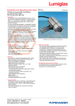
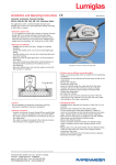
•Electrical data Part 1. Light generator
(luminaire enclosure)
1.1 Protective conductor terminal,
external
1.2 Locking screw
1.3 Locking plate
1.4 Screw-type sight glass
1.5 Protective conductor terminal,
internal
1.6 Ex terminal
1.7 Cable entry gland
M20 x 1.5 (Ex e)
1.8 Cable bushing
M20 x 1.5 (Ex d)
2.
2.1
2.2
2.3
Light guide,
stainless steel
Attachment piece
on light generator,
stainless steel
Protective hose,
stainless steel
Light guide head,
stainless steel
•Mechanical assembly:
-Caution: Avoid looking into the light source – risk of
damage to the eyes!
-The light generator (1) is mounted at a suitable place on the reactor, apparatus, etc., using the fastening element provided. The light guide must be mounted free of tension or twisting with a bending radius of at least 170 mm and installed with the light guide head holder.
-The light guide head (2.3) is screwed to the place to be
illuminated using the relevant stainless steel fastening unit.
•Installation position:
The light guide housing must be installed horizontally or
with the light guide at the top.
•Replacement parts and accessories:
-Please use only original spare parts.
-Have the luminaire serviced by the manufacturer whenever necessary.
•Maintenance:
-Keep the luminaire clean.
-Once the luminaire has been opened, the thread of the
screwed glass lens (1.4) should be greased again (e.g. with AEMA-SOL 6 B, made by A.E. Matthes)
-The average service life of the bulb should be observed.
Product
Part No.
Claw spanner for screwed glass lens
6805.002.00
Mounting brackets for light
generator, straight
0354.005.00
Fastener for light guide head
1947.005.00
Screwed glass lens (light outlet)
1774.089.00
O-ring seal (Viton) for screwed
glass lens
0862.020.00
O-ring seal for light guide
0862.082.00
Halogen bulb 12 V/20 W
3232.279.00
Halogen bulb 10 V/39 W
3232.280.00
Light guide 0.5 m
3383.021.00
Light guide 1.0 m
3383.022.00
Light guide 1.5 m
3383.023.00
Light guide 2.0 m
3383.024.00
Light guide 2.5 m
3383.025.00
Light guide 3.0 m
3383.026.00
Timer module 10 V
3908.022.00
Timer module 12 V
3908.014.00
All dimensions in mm unless stated otherwise. Subject to change without prior notice.
ric 01.13
F.H.Papenmeier GmbH & Co. KG · division Lumiglas
Talweg 2 · 58239 Schwerte · GERMANY
phone: +49-2304 205-0 · fax: +49-2304 205-206
[email protected] · www.lumiglas.de