1
Taster-Modul Basic© Merten 2009V5110-581-0208/13
en
Taster-Modul kennenlernen
Taster-Modul Basic
Gebrauchsanleitung
Mit dem Taster-Modul Basic (im Folgenden Modul genannt) können Sie verschiedene Funktionen ausführen,
wie z. B.:
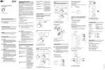
Anschlüsse, Anzeigen und
Bedienelemente
Modul bedienen: Lokale Licht- und
Jalousiesteuerung
Lokale Licht- oder Jalousieszene
aufrufen
Vorderseite:
Die Bedienung des Moduls wird stellvertretend am
Beispiel des 2fach-Taster-Moduls gezeigt.
Standard-Szenen
§
• Schalten, Dimmen, Jalousie steuern
• Lichtszenen und Jalousieszenen Basic aufrufen, ändern und speichern.
Verbraucher ein-/ausschalten
$
„
Komplettieren Sie das Modul mit den empfangenden
Einsätzen zum Schalten, Dimmen oder Jalousie/Rollladen steuern, um lokale Licht- und Jalousiesteuerung
auszuführen.
A
Schalten:
Rückseite:
• Elektronik-Schalt-Einsatz
• Relais-Schalt-Einsatz
System M
• Elektronik-Schalt-Einsatz, 2fach
• Relais-Schalt-Einsatz,
2fach
System M
Taster-Modul Basic, 2fach
Art.-Nr. MEG5120-0300
Taster-Modul, 1fach:
lokal schalten
Im Folgenden wird „Jalousie/Rollladen“ nur mit
„Jalousie“ bezeichnet.
A
Funktionsübersicht der Module auf
empfangenden Einsätzen
Taster-Modul Basic, 1fach
Art.-Nr. MEG5110-0300
!
Taster-Modul, 2fach:
lokal beide Kanäle separat
schalten
LEDs (Status, Orientierung)
English operating instructions
|
You will find the English version of these operating instructions at:
www.merten.com
• Steuerungs-Einsatz
1-10 V
• DALI-Steuerungs-Einsatz
• Universal-Dimmer-Einsatz, 2fach
– Komplettieren Sie das Taster-Modul Basic, 1fach
und 2fach mit:
• entsprechenden Einsätzen
(siehe Funktionsübersicht)
< 0,5 s
• Rahmen im Design System M.
Für Ihre Sicherheit
¼
GEFAHR
Gefahr von schweren Sach- und Personenschäden, z. B. durch Brand oder elektrischen
Schlag, aufgrund einer unsachgemäßen
Elektroinstallation.
Eine sichere Elektroinstallation kann nur gewährleistet werden, wenn die handelnde Person nachweislich über Grundkenntnisse auf folgenden
Gebieten verfügt:
• Anschluss an Installationsnetze
• Verbindung mehrerer elektrischer Geräte
• Verlegung von Elektroleitungen
Über diese Kenntnisse und Erfahrungen verfügen in der Regel nur ausgebildete Fachkräfte im
Bereich der Elektro-Installationstechnik. Bei
Nichterfüllung dieser Mindestanforderungen
oder Missachtung droht für Sie die persönliche
Haftung bei Sach- und Personenschäden.
• Die Geräte der Jalousieszene fahren zunächst in die
obere Position. Nach einer Laufzeit von 2 Minuten fahren sie in die gespeicherte Position.
• rechte Taste: Kanal 1
• linke Taste: Kanal 2
A
< 0,5 s
< 0,5 s
A Modul-Schnittstelle
Funktionsübersicht der Module auf
sendendem Einsatz
Komplettieren Sie das Modul mit dem sendenden Zentralstellen-Einsatz, um globale Licht- und Jalousiesteuerung über den PlusLink (PL) auszuführen.
2
B
Beispiel für globales Ein-/Ausschalten und Dimmen
von 1-4 PL-Linien
Bei Betätigung des Taster-Moduls auf dem Zentralstellen-Einsatz werden alle Verbraucher in den PL-Linien
gemeinsam gesteuert:
• langer Tastendruck (> 0,5 s): dimmen
A
>3s
Verbraucher dimmen
C
D
PL4 PL3 PL2
In Kombination mit 1fach-Einsatz
A Einsatz (siehe Funktionsübersicht)
B Rahmen
C Taster-Modul, 1fach/2fach
< 0,5 s
3 Szene speichern: Taste S1 oder S2 lang drücken.
< 0,5 s
B
> 0,5 s
Lokale Jalousieszenen Basic ändern
und speichern
C
(Nur für Taster-Modul, 2fach)
In Kombination mit 2fach-Einsatz
Bei Jalousieszenen Basic können Sie nur die festen Positionswerte „ vollständig hoch/runter“ speichern.
• rechte Taste: Kanal 1
1 Jalousie in die obere Position fahren und 2 Minuten
Laufzeit abwarten bis die Status-LED erlischt.
• linke Taste: Kanal 2
> 0,5 s
> 0,5 s
3
1
2
Bei Verwendung des 1fach-Taster-Moduls werden beide
Kanäle gleichzeitig gedimmt.
Jalousien steuern
• hoch-/runterfahren (> 0,5 s)
• schrittweise auf/ab (< 0,5 s)
PL1
2 Helligkeitswert einstellen.
Bei erfolgreicher Speicherung schalten sich alle Lampen
kurz aus und wieder ein. Danach nehmen die Lampen
den gespeicherten Helligkeitswert an.
> 0,5 s
D Wippen, 1fach/2fach
Globale Lichtsteuerung
• kurzer Tastendruck (< 0,5 s): ein-/ausschalten
3
Bei Verwendung des 1fach-Taster-Moduls werden beide
Kanäle gleichzeitig geschaltet.
A
• Zentralstellen-Einsatz
Taster-Modul, 2fach:
global schalten, global
dimmen, global hoch-/runterfahren, globale Licht-/
Jalousieszenen aufrufen
und speichern
Die globale Steuerung über PlusLink ist möglich
in Kombination von Zentralstellen-Einsatz und
Taster-Modul.
1 Szene aufrufen: Taste S1 oder S2 kurz drücken.
Modul montieren
Globale Licht- und Jalousiesteuerung:
Taster-Modul, 1fach:
global schalten, global
dimmen, global hoch-/runterfahren
Lokale Lichtszenen ändern und
speichern
(Nur für Taster-Modul, 2fach)
Taster-Modul, 1fach:
lokal beide Kanäle gleichzeitig dimmen
Taster-Modul, 2fach:
lokal hoch-/runterfahren,
lokale Jalousieszenen Basic aufrufen und speichern
(vollständig hoch/runter,
keine beliebige Position)
Schalten, Dimmen, Jalousie steuern, Szenen aufrufen
• mechanischem Taster/Doppeltaster
|
• Die Geräte der Lichtszene nehmen den gespeicherten
Helligkeitswert an.
D
• entsprechenden 1fach-, bzw. 2fach-Wippen im
Design System M
Licht aus / Jalousie runter
• Zentralstellen-Einsatz oder Nebenstelle Plus, 1fach/
2fach:
Modul bedienen: Globale Licht- und
Jalousiesteuerung über PlusLink
In Kombination mit 2fach-Einsatz
Taster-Modul, 2fach:
lokal schalten und dimmen, lokale Lichtszenen
aufrufen und speichern
• Jalousiesteuerungs-Ein- Taster-Modul, 1fach:
satz
lokal hoch-/runterfahren
S2:
Verbraucher von anderer Stelle über
PlusLink steuern mit
1 Szene aufrufen: Taste S1 oder S2 kurz drücken.
Taster-Modul, 1fach:
lokal schalten und dimmen
Jalousien/Rollladen steuern:
Licht an (100 %) / Jalousie hoch
! - $ Tasten des Taster-Moduls, 2fach
Taster-Modul, 2fach:
lokal beide Kanäle separat
dimmen
Notwendiges Zubehör
S1:
< 0,5 s
! - " Tasten des Taster-Moduls, 1fach
Dimmen:
• Universal-Dimmer-Einsatz
Ab Werk verfügen alle Geräte über Voreinstellungen für
eine Licht- bzw. Jalousieszene.
In Kombination mit 1fach-Einsatz
Taster-Modul, 2fach:
lokal schalten, lokale Lichtszenen aufrufen und speichern
Taster-Modul, 1fach:
lokal beide Kanäle gleichzeitig schalten
(Nur für Taster-Modul, 2fach)
Modul von anderer Stelle steuern
B
> 0,5 s
A Modul auf Zentralstellen-Einsatz
B Einsätze zum Schalten und Dimmen (siehe Funktionsübersicht)
Globale Jalousiesteuerung
Beispiel für globales Hoch-/Runterfahren und
schrittweises Auf/Ab von 1-4 PL-Linien
>3s
2 Gewünschte Position der Jalousie einstellen:
– Position „hoch“: keine weitere Einstellung nötig
Bei Betätigung des Taster-Moduls auf dem Zentralstellen-Einsatz werden alle Verbraucher in den PL-Linien
gemeinsam gesteuert:
• langer Tastendruck (> 0,5 s): hoch-/runterfahren
• kurzer Tastendruck (< 0,5 s): schrittweise auf/ab
– Position „runter“: Jalousie runterfahren
3 Szene speichern: Taste S1 oder S2 lang drücken.
Bei erfolgreicher Speicherung fahren die Jalousien einen Schritt ab und wieder auf.
A
< 0,5 s
PL4 PL3 PL2
< 0,5 s
PL1
> 0,5 s
> 0,5 s
B
< 0,5 s
< 0,5 s
> 0,5 s
> 0,5 s
B
A Modul auf Zentralstellen-Einsatz
B Jalousiesteuerungs-Einsatz
V5110-581-02 08/13
de
Modul bedienen: Globale Szenen über
PlusLink aufrufen, ändern und
speichern
|
Globale Szenen über PlusLink sind möglich in
Kombination von Zentralstellen-Einsatz und
Taster-Modul, 2fach.
|
Wenn Sie eine Szene speichern, dann betrifft das
alle angeschlossenen Geräte der PL-Linien.
Lichtszenen ändern und speichern
Am Beispiel eines Dimmers:
1
>3s
3 Prüfen, ob sich alle Geräte im gewünschten Zustand
befinden.
2 Helligkeitswerte der Lampen, die Sie verändern
möchten, am empfangenden Gerät einstellen.
4 Szene speichern.
3 Szene speichern: Taste S1 oder S2 lang drücken.
S2:
Licht aus / Jalousie runter
Paniktaster:
Licht an (100 %) / Jalousie runter
1 Szene aufrufen: Taste S1 oder S2 kurz drücken.
Bei erfolgreicher Speicherung schalten sich alle Lampen
kurz aus und wieder ein. Danach nehmen die Lampen
den gespeicherten Helligkeitswert an.
Jalousieszenen ändern und speichern
A
A
D
C
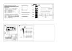
Bedienelemente
Taster-Modul, 1fach:
Taster-Modul, 2fach:
Anschluss:
2 Tasten
4 Tasten
Modul-Schnittstelle mit
8 Kontaktstiften
Gothaer Straße 29, 40880 Ratingen
In Kombination mit Zentralstellen-Einsatz
Bedienung
Rückmeldung
rote LED blinkt 1x
bei Betätigung
www.merten.de
www.merten-austria.at
Kundenbetreuung:
Telefon: +49 2102 - 404 6000
3
Rückmeldung
10x
=
10x
=
>3s
Memory-Funktion ein-/ausschalten
1 Szene aufrufen: Taste S1 oder S2 kurz drücken.
(Nur in Kombination mit Dimmer-Einsätzen)
2 A Positionen (vollständig hoch/runter) der Jalousien, die Sie verändern möchten, am empfangenden Gerät einstellen.
Das Gerät merkt sich die zuletzt eingestellte Helligkeit.
B Positionen (beliebige Werte) der Jalousien, die
Sie verändern möchten, am empfangenden Gerät einstellen.
D
Taster-Modul, 2fach in
Kombination mit
2fach-Einsatz:
2 Status-LEDs
2 Orientierungs-LEDs
LED blinkt 4x
A
PL3
Taster-Modul, 2fach in
Kombination mit
1fach-Einsatz:
1 Status-LED
1 Orientierungs-LED
Schneider Electric GmbH c/o Merten
Bedienung
B
B
1 Status-LED
1 Orientierungs-LED
Standard: ausgeschaltet
< 0,5 s
2
PL4
rote LED leuchtet
bei geschalteter
Last
Taster-Modul, 1fach:
Orientierungs-LED (grün) ein-/ausschalten
1
• Die Geräte der Jalousieszene fahren zuerst in die
oberste Position. Nach Ablauf einer Laufzeit von maximal 2 Minuten fahren die Jalousien in die gespeicherte Position.
PL2
Rückmeldung
Bei Jalousieszenen können Sie in Kombination mit dem
Taster-Modul Basic auf dem empfangenden Einsatz nur
die festen Positionswerte „vollständig hoch/runter“
(2A) speichern.
In Kombination mit den Taster-Modulen Comfort und
Comfort Plus auf dem empfangenden Einsatz können
Sie beliebige Positionswerte (2B) speichern.
• Die Geräte der Lichtszene nehmen den gespeicherten
Helligkeitswert an.
PL1
In Kombination mit 2fach-Einsatz
Bedienung
1 Szene aufrufen: Taste S1 oder S2 kurz drücken.
Licht an (100 %) / Jalousie hoch
Rückmeldung
3
2 Zustände einzelner Geräte in der Licht- bzw. Jalousieszene verändern.
S1:
Anzeigeelemente
rote LED leuchtet
bei geschalteter
Last
1 Szene aufrufen (schon ab Werk sind Standard-Szenen eingestellt).
Ab Werk verfügen alle Geräte über Voreinstellungen für
eine Licht- bzw. Jalousieszene.
Status-LED (rot) des Moduls
Bedienung
< 0,5 s
Um eine Szene nach Ihren Wünschen zu ändern und zu
speichern, gehen Sie folgendermaßen vor:
Standard-Szenen
Technische Daten
In Kombination mit 1fach-Einsatz
2
Globale Licht- oder Jalousieszenen
aufrufen
Modul bedienen: Basisfunktionen
Standard: ausgeschaltet
Bedienung
Rückmeldung
LED blinkt 4x
3 Szene speichern: Taste S1 oder S2 lang drücken.
Bei erfolgreicher Speicherung fahren die Jalousien einen Schritt ab und wieder auf.
6x
=1
6x
=2
1 Memory-Funktion einschalten
max. 10
max. 10
A Modul auf Zentralstellen-Einsatz
B Paniktaster (mechanischer Taster)
C PL-Linie 4 mit Jalousieszene: JalousiesteuerungsEinsatz
D PL-Linie 2 und 3 mit Lichtszene: Einsätze zum
Schalten und Dimmen (siehe Funktionsübersicht)
|
Präsenzmelder in den PL-Linien rufen keine Szenen auf, sondern schalten Verbraucher für 24
Stunden ein oder aus (S1/S2).
2 Memory-Funktion ausschalten
Auf Werkseinstellung zurücksetzen
Bedienung
Rückmeldung
LEDs blinken 8x
10 s
V5110-581-02 08/13
max. 10
Push-button module Basic© Merten 2009V5110-581-0208/13
en
Getting to know the push-button
module
Push-button module Basic
Operating instructions
With the push-button module Basic (referred to below as
module), you can carry out various functions such as:
• switching, dimming and controlling blinds
• retrieving, changing and saving light scenes and blind
scenes Basic.
Function overview of the modules on
sending insert
Complete the module with the sending central unit insert
in order to carry out global light and blind control via the
PlusLink (PL).
Global light and blind control:
• Central unit insert
Push-button module,
1-gang:
globally switching, globally
dimming, globally raising/
lowering
Function overview of the modules on
receiving inserts
Complete the module with the receiving inserts for
switching, dimming or controlling blind/roller shutter in
order to carry out local light and blind control.
• Relay switch insert
Push-button module Basic, 1-gang
Art. no. MEG5110-0300
• Electronic switch insert, Push-button module,
2-gang
1-gang:
locally switching both
• Relay switch insert, 2channels simultaneously
gang
System M
Push-button module Basic, 2-gang
Art. no. MEG5120-0300
English operating instructions
|
You will find the English version of these operating instructions at:
www.merten.com
Necessary accessories
– Complete the push-button module Basic, 1-gang and
2-gang, with
• corresponding inserts (see function overview)
Push-button module,
2-gang:
locally switching both
channels separately
Dimming:
• Universal dimmer insert Push-button module,
1-gang:
• 1-10 V insert
locally switching and dim• DALI insert
ming
DANGER
Risk of serious damage to property and personal injury, e.g. from fire or electric shock,
due to incorrect electrical installation.
Safe electrical installation can only be ensured if
the person in question can prove basic knowledge in the following areas:
• Connecting to installation networks
Connections, displays and operating
elements
Front:
§
Push-button module,
1-gang:
locally dimming both channels simultaneously
(Only for push-button module, 2-gang)
Standard scenes
All devices are delivered from the factory with presettings for a light or blind scene.
S1:
light on (100 %) / blind up
S2:
light off / blind down
< 0,5 s
A
switching, dimming, controlling blinds, retrieving
scenes
Operating the module: global light and
blind control via PlusLink
1 Retrieve scene: press the S1 or S2 push-button
briefly.
• The devices of the light scene adopt the saved brightness value.
In combination with 2-gang insert
• right push-button: channel 1
• left push-button: channel 2
< 0,5 s
Changing and saving local light scenes
Example of globally switching on/off and dimming
the 1-4 PL lines:
>3s
When using the 1-gang push-button module, both channels are switched simultaneously.
Dimming loads
• long press on the push-button (> 0.5 s): dimming
A
2 Set the brightness value.
3 Save scene: press the S1 or S2 push-button for
more than 3 seconds.
In combination with 1-gang insert
Rear:
On operation of the push-button module on the central
unit insert, all loads in the PL lines are controlled together:
• short press on the push-button (< 0.5 s): switching on/
off
3
„
! - $ Push-buttons of the push-button module,
2-gang
The global control via PlusLink is possible with
the combination of a central unit insert and a
push-button module.
Global light control
1 Retrieve scene: press the S1 or S2 key briefly.
! - " Push-buttons of the push-button module,
1-gang
|
• The devices of the blind scene initially move to upper
position. After a runtime of 2 minutes they move to the
saved position.
(Only for push-button module, 2-gang)
LEDs (status, orientation)
Controlling loads from another location
via PlusLink with
• Central unit insert or side controller Plus, 1-gang/2gang:
< 0,5 s
2
$
Controlling the module from another
location
• mechanical push-button/double push-button
All lights are switched off briefly and then back on again
to indicate that the saving procedure has been successful. Then the lights adopt the saved brightness value.
> 0,5 s
Changing and saving local blind scenes
Basic
PL4 PL3 PL2
PL1
< 0,5 s
B
(Only for push-button module, 2-gang)
A
• right push-button: channel 1
• left push-button: channel 2
A Module interface
> 0,5 s
> 0,5 s
1 Move the blind to the upper position and wait for the
running time of 2 minutes until the status LED goes
out.
3
Mounting the module
1
Push-button module,
1-gang:
locally raising/lowering
A
2
< 0,5 s
> 0,5 s
For blind scenes Basic, it is only possible to save the set
position values of "completely up/down".
In combination with 2-gang insert
Controlling blinds/roller shutter:
• Blind control insert
Retrieving local light or blind scenes
In combination with 1-gang insert
A
B
> 0,5 s
A Module on central unit insert
B Inserts for switching and dimming (see function
overview)
>3s
B
Push-button module,
2-gang:
locally raising/lowering, retrieving and saving local
blind scenes Basic (completely up/down, not any
position)
When using the 1-gang push-button module, both channels are dimmed simultaneously.
C
D
Controlling blinds
• raising/lowering (> 0.5 s)
• up/down in steps (< 0.5 s)
• Connecting several electrical devices
C
• Laying electric cables
These skills and experience are normally only
possessed by skilled professionals who are
trained in the field of electrical installation technology. If these minimum requirements are not met
or are disregarded in any way, you will be solely liable for any damage to property or personal injury.
Switching loads on/off
< 0,5 s
!
• Universal dimmer insert, Push-button module,
2-gang
1-gang:
locally dimming both channels simultaneously
• System M frames.
For your safety
The "Blind/roller shutter" will be referred to below as
"blind".
Push-button module,
2-gang:
locally switching and dimming, retrieving and saving
local light scenes
• corresponding 1-gang or 2-gang rockers in the design
System M
¼
Push-button module,
1-gang:
locally switching
Push-button module,
2-gang:
locally switching, retrieving
and saving local light
scenes
System M
The operation of the module is illustrated below using the
2-gang push-button module as an example.
Push-button module,
2-gang:
globally switching, globally
dimming, globally raising/
lowering, globally retrieving and saving light/blind
scenes
Switching:
• Electronic switch insert
Operating the module: local light and
blind control
D
2 Set the desired position of the blind:
– position “up“: no further setting needed
– position “down“: lower the blind
3 Save scene: press the S1 or S2 push-button for 3
seconds or longer.
The blinds move down a step and then back up to indicate that the saving procedure has been successful.
< 0,5 s
> 0,5 s
A Insert (see function overview)
B Frame
C Push-button module, 1-gang/2-gang
D Rockers, 1-gang/2-gang
< 0,5 s
> 0,5 s
V5110-581-02 08/13
de
Global blind control
Retrieving global light or blind scenes
Changing and saving blind scenes
Switching memory function on/off
Example of global raising/lowering and up/down
in steps of the 1-4 PL lines
Standard scenes
In combination with the push-button module Basic on the
receiving insert, you can only save the fixed position values of "completely up/down" (2A) for blind scenes.
In combination with the push-button modules Comfort or
Comfort Plus on the receiving insert, you can save any
position values (2B).
(Only in combination with dimmer inserts)
• long press on the push-button (> 0.5 s): raising/lowering
• short press on the push-button (< 0.5 s): up/down in
steps
S1:
light on (100 %) / blind up
S2:
light off / blind down
Panic button:
light on (100 %) / blind down
PL4 PL3 PL2
< 0,5 s
PL1
1 Retrieve scene: press the S1 or S2 key briefly.
• The devices of the blind scene initially move to the uppermost position. After a running time of maximum 2
minutes has elapsed, the blinds move to the saved position.
< 0,5 s
2
A
B
> 0,5 s
< 0,5 s
A
B
PL3
B Blind control insert
D
D
C
Operating the module: retrieving,
changing and saving global scenes via
PlusLink
>3s
Resetting to default settings
Status feedback
LEDs flash 8x
10 s
2 A Set the positions (completely up/down) of the
blinds that you want to change on the receiving
device.
3 Save scene: press the S1 or S2 key for more than 3
seconds.
Technical data
The blinds move down a step and then back up to indicate that the saving procedure has been successful.
Display elements
Operating the module: basic functions
max. 10
max. 10
max. 10
Status LED (red) of the module
In combination with 1-gang insert
When you save a scene, this affects all connected devices of the PL lines.
B Panic button (mechanical push-button)
Operation
C PL line 4 with blind scene: Blind control insert
Status feedback
red LED lights up
when load is
switched on.
D PL line 2 and 3 with light scene: Inserts for switching
and dimming (see function overview)
|
2 Change the states of individual devices in the light
and/or blind scene.
4 Save scene.
=2
Operation
A Module on central unit insert
3 Check that all devices have the state you require.
6x
2 Switching off memory function
Global scenes via PlusLink are possible with the
combination of a central unit insert and a pushbutton module, 2-gang.
1 Retrieve scene (standard scenes are set at the
factory).
=1
B Set the positions (any values) of the blinds that
you want to change on the receiving device.
A Module on central unit insert
Proceed as follows to change and save a scene according to your requirements:
6x
1 Retrieve scene: press the S1 or S2 key briefly.
PL4
B
|
Status feedback
1 Switching on memory function
3
A
PL2
> 0,5 s
|
Operation
LED flashes 4x
PL1
B
Standard: switched off
1
• The devices of the light scene adopt the saved brightness value.
A
The device memorises the brightness level that was
last set.
Presence detectors in the PL lines do not retrieve
scenes, but switch loads on or off (S1/S2) for 24
hours.
Changing and saving light scenes
Push-button module,
1-gang:
1 status LED
1 orientation LED
Push-button module,
2-gang in combination
with 1-gang insert:
1 status LED
1 orientation LED
Push-button module,
2-gang in combination
with 2-gang insert:
2 status LEDs
2 orientation LEDs
Operating elements
Push-button module,
1-gang:
2 push-buttons
Push-button module,
2-gang:
4 push-buttons
In combination with 2-gang insert
Operation
Connection:
Status feedback
red LED lights up
when load is
switched on.
Using a dimmer as an example:
1
module interface with
8 contact pins
Schneider Electric GmbH c/o Merten
Gothaer Straße 29, 40880 Ratingen
www.merten.com
www.merten-austria.at
< 0,5 s
In combination with central unit insert
Operation
2
Status feedback
red LED flashes 1x
after operation.
3
Customer care centre:
Phone: +49 2102 - 404 6000
>3s
1 Retrieve scene: press the S1 or S2 key briefly.
2 Set the brightness values of the lights that you want
to change on the receiving device.
3 Save scene: press the S1 or S2 key for more than 3
seconds.
All lights are switched off briefly and then back on again
to indicate that the saving procedure has been successful. Then the lights adopt the saved brightness value.
Switching the orientation LED (green)
on/off
Standard: switched off
Operation
Status feedback
LED flashes 4x
10x
=
10x
=
V5110-581-02 08/13
On operation of the push-button module on the
central unit insert, all loads in the PL lines are controlled
together:
All devices are delivered from the factory with presettings for a light or blind scene.