1
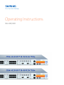
Operating Instructions
SG 430/450
Operating Instructions
Foreword
We are pleased to welcome you as a new customer of our Sophos SG appliances.
To install and configure the hardware appliance you can use the following
documents:
ÌÌ Hardware Quick Start Guide: Connection to the system peripherals in a few steps
ÌÌ Operating Instructions: Notes on the security and
commissioning of the hardware appliance
ÌÌ Administration Guide: Installing and configuring the software appliance
The Hardware Quick Start Guide and the Security Notes are also delivered in printed
form together with the hardware appliance. The instructions must be read carefully
prior to using the hardware and should be kept in a safe place.
You may download all user manuals and additional documentation from the support
webpage at: sophos.com/support
Security Symbols
The following symbol and its meaning appears in the Hardware Quick Start Guide,
Security Notes and in these Operating Instructions.
Caution and Important Note. If these notes are not correctly observed:
ÌÌ This is dangerous to life and the environment
ÌÌ The appliance may be damaged
ÌÌ The functions of the appliance will be no longer guaranteed
ÌÌ Sophos shall not be liable for damages arising from a
failure to comply with the security notes
Designed Use
The hardware appliances are developed for use in networks. The SG 430/450 models
may be operated as a standalone appliance. The hardware appliance can be used in
commercial, industrial and residential environments.
The SG 430/450 models belongs to the appliance group A.
The hardware appliance must be installed pursuant to the current installation notes.
Otherwise failure-free and safe operation cannot be guaranteed. The EU declaration
of conformity is available at the following address:
Sophos Technology GmbH
Amalienbadstr. 41/Bau 52
76227 Karlsruhe
Germany
SG 430/450
1
Operating Instructions
CE Labeling, FCC and Approvals
The SG 430/450 appliances comply with FCC Class A, CE, C-Tick, VCCI and UL.
Important Note: For computer systems to remain CE and FCC compliant, only CE
and FCC compliant parts may be used. Maintaining CE and FCC compliance also
requires proper cable and cabling techniques.
Operating Elements and Connections
SG 430/450 (rev.1)
Reset
Optional FleXi Port module
1 default module
(8* 10/100/1000
Base-TX ports)
MGMT
Optional FleXi Port module
LED: Power
Hard disk
LCD
COM
LCD control
joystick
SG 4xx (rev.1)
Power switch
Primary Power
Connector
SG 430/450
Slot for
optional power
supply module
(SG450 only)
Fans
VGA
USB
2
Operating Instructions
Controls
Power (LED Display)
Green
Power on
Red
HDD (Hard disk access)
LEDs on each Ethernet connector
ACT/LNK
Speed
(RJ45 ports)
Speed
(SFP+ ports)
Green
Constantly
1.The Ethernet port is receiving power.
2.Good connection between the
Ethernet port and hub.
Off
1.The adapter and switch are not receiving power.
2.No connection between both ends of network.
3.Network drivers have not been loaded
or do not function correctly.
Flashing
The adapter is sending or receiving
network data. The frequency of the flashes
varies with the amount of traffic.
Orange
On
If ACT/LNK LED is on then this LED shows
operating speed at 1000 Mbps
Green
On
If ACT/LNK LED is on then this LED
shows operating speed at 100 Mbps
Off
If ACT/LNK LED is on then this LED
shows operating speed at 10 Mbps
Blue
On
If ACT/LNK LED is on then this LED
shows operating speed at 10 Gbps
Orange
On
If ACT/LNK LED is on then this LED
shows operating speed at 1 Gbps
Off
Ports not operational
LCD and Control Keys
The Sophos SG 430/450 units have an LCD and an operating unit controlled by a
joystick. In the LCD, 16 characters per line can be displayed. The display contains in
four cycling views information on the hardware and specific system states.
SOPHOS
Protection
UTM 9.xxx
10 days 01:43:17
CPU xx%
xx% yy% zz%
SG 430/450
After the security appliance has booted this message is displayed.
Sophos UTM version
Appliance Uptime
CPU load information
Average Load in the last 1, 5 and 15 minutes
RAM x% y GB
SWAP x% y GB
Memory usage
all in x kbits/sec
out y kbits/sec
Traffic on interface
3
Operating Instructions
With the joystick five actions can be executed
ÌÌ Change IP Address: This option enables the user to change the interface’s IP
address and netmask. All available and enabled IP addresses can be changed.
ÌÌ Reboot machine: The security appliance is rebooted. The reboot
action will shut down the system completely and reboot.
ÌÌ Shut down: The security appliance is shut down. The shut down action allows
you to turn off the system, and allows you to cleanly stop all running services.
ÌÌ Factory reset: All settings are reset to the factory settings. The factory reset
function sets all of the configuration settings and options to their original state.
All data entered after the initial installation will be deleted, including the HTTP
proxy cache, the entire email queue, accounting and reporting data, passwords,
and uninstalled Up2Date packages. The version of the software will not change.
That is, all firmware and pattern updates that have been installed will be retained.
ÌÌ Disable OTP (One Time Password) authentication: The OTP
authentication will be disabled for the selected options. This feature only
handles webadmin and shell access options if they are enabled.
The joystick has the following functions
UP/DOWN/LEFT/RIGHT:
Move the joystick into any direction to switch between different menus or characters
within a line
ENTER:
Press the joystick to execute the configuration action
Change IP Address
1. Press Enter.
The following message will be displayed: Change IP addr
2. Press Enter.
The following message will be displayed:
IP address (Ethx) XXX.XXX.XXX.XXX/YY
3. Move joystick up/down to select the interface or
move left/right to exit from this view.
4. Press Enter . The IP address with underlined cursor in edit mode is shown.
5. Move joystick up/down to change the digit at the underlined cursor position.
6. Move joystick left/right to move cursor to next or previous positions.
7. To exit, move the cursor to the beginning and move joystick left.
8. When cursor is at the right most digit move joystick right. The following
message is displayed.
Netmask
YY
9. Move joystick up/down to increment or decrement the Netmask
value or left to exit the edit mode without saving.
10. Move joystick right to save the changed IP address with netmask.
SG 430/450
4
Operating Instructions
Starting reboot machine
1. Press the Enter key.
2. Move joystick down.
The following message will be displayed:
Reboot Machine
3. Press Enter.
The following message will be displayed:
Are you sure?
Move joystick up/down to select Yes (y) or No (n).
4. Press Enter to confirm your settings.
The reboot machine action will now start.
Starting shut down
1. Press Enter.
2. Move joystick down twice.
The following message will be displayed:
Shutdown
3. Press Enter.
The following message will be displayed:
Are you sure?
Move joystick up/down to select Yes (y) or No (n).
4. Press Enter to confirm your settings.
The shut down action will now start.
Starting factory reset
1. Press Enter.
2. Move joystick down three times.
The following message will be displayed:
Factory Reset
3. Press Enter.
The following message will be displayed:
All Data Erased! Are you sure?
Move joystick up/down to select Yes (y) or No (n).
4. Press Enter to confirm your settings. The factory reset action will now start.
SG 430/450
5
Operating Instructions
Disabling OTP (One Time Password) Authentication
1. Press Enter.
2. Move joystick down four times.
The following message will be displayed:
OTP Recovery
3. Press Enter.
The following message will be displayed:
Disable OTP
xxxxxx
If there is no option to disable available the following message will be displayed:
Not Available
Move joystick left/right to quit disable OTP menu.
4. Move joystick up/down to select the feature to disable (if enabled).
5. Press Enter.
The following message will be displayed:
Disable xxxxx
Are you sure?
6. Move joystick up/down to select Yes (y) or No (n).
7. Press Enter to confirm.
Putting into Operation
Caution: Risk of explosion if battery is replaced by an incorrect type. Dispose of used
batteries according to the instructions.
Scope of Supply
The supplied parts are indicated in the Hardware Quick Start Guide.
Mounting Instructions
The SG 430/450 appliances are designed for use in racks. Please consider the
following security tips:
Important Note: Functional reliability outside of a rack cannot be guaranteed.
Warnings and Precautions
The appliance can be operated safely if you observe the following notes and the notes
on the appliance itself.
SG 430/450
6
Operating Instructions
Rack Precautions
ÌÌ Ensure that the leveling jacks on the bottom of the rack are fully
extended to the floor with the full weight of the rack resting on them.
ÌÌ In single rack installation, stabilizers should be attached to the rack.
ÌÌ In multiple rack installations, the racks should be coupled together.
ÌÌ Always make sure the rack is stable before extending a component from the rack.
ÌÌ You should extend only one component at a time—extending two or
more simultaneously may cause the rack to become unstable.
General Server Precautions
ÌÌ Review the electrical and general safety precautions that came
with the components you are adding to your appliance.
ÌÌ Determine the placement of each component in
the rack before you install the rails.
ÌÌ Install the heaviest server components on the bottom
of the rack first, and then work up.
ÌÌ Allow the hot plug hard drives and power supply
modules to cool before touching them.
ÌÌ Always keep the rack‘s front door, all panels and server components
closed when not servicing to maintain proper cooling.
Rack Mounting Considerations
ÌÌ Ambient operating temperature: If installed in a closed or multiunit rack assembly, the ambient operating temperature of the rack
environment may be greater than the ambient temperature of the room.
Therefore, you should install the equipment in an environment compatible
with the manufacturer’s maximum rated ambient temperature.
ÌÌ Reduced airflow: Equipment should be mounted into a
rack with sufficient airflow to allow cooling.
ÌÌ Mechanical loading: Equipment should be mounted into a rack so that a
hazardous condition does not arise due to uneven mechanical loading.
ÌÌ Circuit overloading: Consideration should be given to the connection
of the equipment to the power supply circuitry and the effect that any
possible overloading of circuits might have on overcurrent protection
and power supply wiring. Appropriate consideration of equipment
nameplate ratings should be used when addressing this concern.
ÌÌ Reliable ground: Reliable grounding must be maintained at all times.
To ensure this, the rack itself should be grounded. Particular attention
should be given to power supply connections other than the direct
connections to the branch circuit (i.e., the use of power strips, etc.).
SG 430/450
7
Operating Instructions
Rack Mounting Instructions
To mount the appliance to the rack you need the delivered rack-mount kits. There are
a variety of rack units on the market, which may mean the assembly procedure will
differ slightly. You should also refer to the installation instructions that came with the
rack unit you are using.
Important Note: Make sure you use the screws supplied with the rack-mount kits.
Using the wrong screws could damage the hardware appliance and would invalidate
your warranty. Please observe the mounting instructions for your rack.
1. Attach the rack-mount kits to the appliance
Place the appliance on a hard, flat surface with the front panel facing you.
Attach the rack–mount kits to the left and right side of the appliance with the
supplied screws.
Make sure the kits are properly attached to the appliance.
2. Choose the rack location
Leave enough clearance in front of the rack so that you can open the front door
completely (~60 cm/25 inches).
Leave approximately 80 cm/30 inches of clearance in the back of the rack to
allow for sufficient airflow and ease in servicing.
This product is for installation only in a restricted access location (no
capitalization) (dedicated equipment rooms, service closets and the like).
3. Slide the appliance into the rack.
4. Attach the front and rear brackets to the rack with
the appropriate screws (not included).
RAID hard disk system (SG 450 only)
The SG 450 is equipped with a RAID system with two hard disks. A RAID system
(redundant array of independent disks) connects several physical hard disks to one
particularly performing logical drive. This type of hard disk system enhances the
transfer rate and data security. Additionally, a RAID system increases the availability
of the security appliance.
The RAID system can be monitored via the graphical user interface WebAdmin.
The current status of the RAID system is displayed on the dashboard in the RAID
status section. In addition to that, a corresponding notification email is sent to the
administrator in the event of a defect in a hard disk.
If a hard disk fails the complete SG 450 unit needs to be exchanged.
Connection and Configuration
How to connect the appliance is described in the Hardware Quick Start Guide. For
configuration you can follow the initial setup wizard described in the WebAdmin
Quick Start Guide or cancel it and perform a manual setup (see the Sophos UTM
Administration Guide).
SG 430/450
8
Operating Instructions
Redundant power supply (SG 450 only)
The SG 450 includes a power supply system which consists of two separate power
supply units. This power supply system increases the availability of the security
appliance, since a defective power supply unit can be exchanged easily and quickly
during operation. The unit is shipped with one power supply unit. The second unit can
be added as an option.
When the system is running error-free, LED on the back of the appliance shows
green. In the event of a hardware defect in one of the power supply units these LEDs
will turn red and you will hear a continuous beeping sound. The warning sound can be
reset by pressing the red buzzer reset switch on the system chassis. This buzzer reset
switch is on the back of the appliance right beside the power supply system.
Important note: If you need to change a power unit because of a defect, remember to
remove the defective power unit from the power supply system, otherwise the whole
security appliance will fail.
Protect yourself from potential burns by wearing protective gloves when exchanging
a power supply unit.
Only use power units which you purchased directly from Sophos or from a Sophos
distribution partner. Please remember that any warranty claims are voided for the
security appliance if a defect has been caused by the use of power units which are not
suited for the system.
For further instructions on how to exchange or add a power supply unit please refer to
the separate mounting instructions delivered with the unit.
SFP GBIC ports
The SG 430/450 models provide the option to add Sophos FleXi Port network
modules with SFP (1 GbE) or SFP+ (1/10GbE) GBIC Ports. The abbreviation SFP
GBIC stands for small form-factore plugable GigaBit interface converter, a flexible
interface which changes electronic signals into optical signals. The converters used
with the appliance are often also called Mini-GBIC or New GBIC.
To use SFP GBIC ports, you will need the appropriate SFP GBIC modules. These
modules are not delivered with the appliance but available through your Sophos
partner. There are different module types. The required type is determined by the
existing network. The following SFP GBIC module types may be used:
SFP:
1000 Base-T
IEEE 802.3 - 1 Gbit/s via Ethernet cable. An Ethernet cable category 5 covers a
maximum distance about 100 meters.
1000 Base-SX
IEEE 802.3 - 1 Gbit/s via fiberglass. Multi-mode fiberglass cables (MMF) cover a
distance of 200 m to 550 m.
1000 Base-LX
IEEE 802.3 - 1 Gbit/s via fiberglass. Here, exclusively singlemode-fiber glass is used.
This transmission option covers approximately 10 km.
SG 430/450
9
Operating Instructions
SFP+:
10GBase-SR
IEEE 802.3 - 10 Gbit/s via fiberglass. Multi-mode fiberglas cables cover a distance of
up to 400 m.
10GBase-LR
IEEE 802.3 - 10 Gbit/s via fiberglass. Single-mode fiberglas cover a distance of
approximately 10 km
Note: The SFP+ ports of the Sophos FleXi Port modules are dual-rate capable
supporting both 1GbE and 10GbE speeds when using appropriate GBICs also
supporting both rates.
Caution: The SFP GBIC and SFP+ ports use lasers to transmit signals over fiber optic
cable. The lasers are compliant with the requirements of a Class 1 Laser equipment
and are inherently eye-safe in normal operation. However, you should never look
directly at a transmit port when it is powered on. Always install appropriate and UL
approved Laser Class I Transceivers, rated 3.3Vdc, max. 1W, in the fiber ports before
using the fiber ports.
Installing a SFP GBIC module:
Please read the operation manual to the SFP GBIC module. Carefully insert the SFP
GBIC module into the port until it engages. The interface is immediately ready for use.
Removing a SFP GBIC module:
1. Remove the fiberglass cable from the module which you wish to remove.
2. Remove the module carefully from the port.
Depending on when you purchased your SFP GBIC module, it may have any of three
different release mechanisms: a plastic tab on the bottom of the mini-GBIC, a wire
bail, or a plastic collar around the mini-GBIC.
Please read the operation manual to the SFP GBIC module.
Serial Console
You can connect a serial console to the COM port of the Sophos UTM hardware
appliances. You can use, for instance, the Hyperterminal terminal program which is
included with most versions of Microsoft Windows to log on to the appliance console.
Use the provided RJ45 to DB9 adapter cable to connect the console to your hardware
appliance.
The required connection settings are:
Bits per second: 38,400, Data bits: 8, Parity: N (none), Stop bits: 1. Access via the
serial console is activated by default on ttyS1. The connections of the appliances
and the respective functionality are listed in chapter “Operating Elements and
Connections.”
SG 430/450
10
Operating Instructions
United Kingdom and Worldwide Sales
Tel: +44 (0)8447 671131
Email: [email protected]
North American Sales
Toll Free: 1-866-866-2802
Email: [email protected]
Oxford, UK | Boston, USA
© Copyright 2014. Sophos Ltd. All rights reserved.
Registered in England and Wales No. 2096520, The Pentagon, Abingdon Science Park, Abingdon, OX14 3YP, UK
Sophos is the registered trademark of Sophos Ltd. All other product and company names mentioned are
trademarks or registered trademarks of their respective owners.
1141-03.14DD.oina.simple
Australia and New Zealand Sales
Tel: +61 2 9409 9100
Email: [email protected]
Asia Sales
Tel: +65 62244168
Email: [email protected]