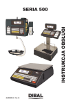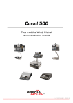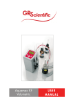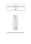
1
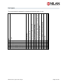
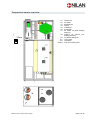
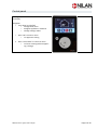
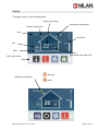
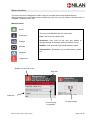
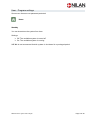
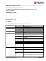
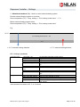
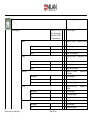
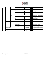
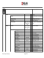
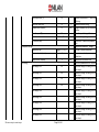
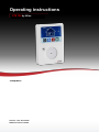
Operating instructions CTS 700 by Nilan Compact P Version: 1.03, 25-03-2015 Software version 1.40.05 We reserve the right to make changes Page 1 of 48 Contents Contents ......................................................................................................................................... 2 Introduction..................................................................................................................................... 3 Unit types ....................................................................................................................................... 4 Temperature sensor overview ......................................................................................................... 5 Control panel .................................................................................................................................. 6 Display ........................................................................................................................................... 7 Menu structure ............................................................................................................................... 8 User - Program settings .................................................................................................................. 9 User – Information ........................................................................................................................ 10 User – Information ......................................................................................................................... 11 User – Settings ............................................................................................................................. 12 User - Settings .............................................................................................................................. 13 User – Standby ............................................................................................................................. 14 User – Standby ............................................................................................................................. 15 User – Fan.................................................................................................................................... 16 User – Temperature ...................................................................................................................... 17 Superuser/ Installer – Program settings ........................................................................................ 18 Superuser/ Installer – Program settings ........................................................................................ 19 Superuser/ Installer – Program settings ........................................................................................ 20 Superuser/ Installer – Information ................................................................................................. 21 Superuser/ Installer – Information ................................................................................................. 22 Superuser/ Installer – Information ................................................................................................. 23 Superuser/ Installer – Settings ...................................................................................................... 24 Superuser/ Installer – Settings ...................................................................................................... 25 Superuser/ Installer – Settings ...................................................................................................... 27 Superuser/ Installer – Settings ...................................................................................................... 28 Superuser/ Installer – Standby...................................................................................................... 29 Superuser/ Installer – Standby...................................................................................................... 30 Superuser/ Installer – Fan ............................................................................................................ 31 Superuser/ Installer – Temperature ............................................................................................... 32 Superuser/ Installer – Temperature ............................................................................................... 33 Superuser/ Installer – Temperature ............................................................................................... 34 Management Overview ................................................................................................................. 35 Temperature............................................................................................................................... 35 Home ......................................................................................................................................... 38 Information ................................................................................................................................ 40 Settings ...................................................................................................................................... 42 Standby ...................................................................................................................................... 47 We reserve the right to make changes Page 2 of 48 Introduction Check that the following papers have been supplied with the product: - User's Manual - Installation If, after reading the guide, you have any other questions concerning installation of the product, please contact your nearest Nilan dealer. Go to www.nilan.dk/en-gb/frontpage/dealers/europe The system is controlled using the multifunctional CTS 700 control panel. The purpose of these instructions is to explain the menus and options available when using CTS 700. As these instructions are designed to apply to different models, you may find descriptions of functions and facilities that are not available on your system. NB: If the system is damaged in any way, the damage must be inspected and repaired by an authorised technician. The system is delivered ready to run. The factory settings are intended to meet most users' needs and it should therefore not be necessary to change any settings other than the main menu settings. We reserve the right to make changes Page 3 of 48 Unit types We reserve the right to make changes X X X X X X X X X X X X De-icing X X X X X X X Pre-heating element (frost protection) X Active cooling via compressor X X X X X X Passive cooling via bypass damper or cold recovery Domestic hot water X X X X X X Optional supplementary heating Heat recovery Compact P Compact P Cool Compact P Cool Solar Compact P Polar Compact P Polar Cool Compact P Polar Cool Solar Optional solar heating connection Type No. The control panel is prepared for use with the following types of units: X X X X X X X X X Page 4 of 48 Temperature sensor overview T1: T2: T3: T4: T5: T6: T7: T8: TPanel T9: T11: T12: TPanel: Outdoor air Air intake Extracted air Output Condenser Evaporator Air intake air (after heating element) Outdoor air (before preheating element) On water heating coil Top of tank Tank base CTS 700 control panel T3 T2 We reserve the right to make changes T1 Page 5 of 48 Control panel To navigate, use the wheel and return button under the display. Navigation • Turn wheel to right/left • Change main menu • Navigate up/down in submenu • Change settings values • Press "OK" to enter a menu • To approve a setting Press "Arrow back" to return to menu • To leave a setting without approving a change We reserve the right to make changes Page 6 of 48 Display The display shows current operating data. Indoor temperature Solar panel temperature Outdoor temperature Clock Fan speed AIR GEO Temperature hot water tank Main menu items Display warning/alarm Warning Alarm We reserve the right to make changes Page 7 of 48 Menu structure The menu structure is designed to make it easy to navigate and find the desired settings. When switching from main menus on the initial screen, the icon you can select in the main menu is enlarged. To select, press "OK". Menu structure Home The menu is subdivided into four user levels: Information User: User level for ordinary user Settings Superuser: User level for the user who wishes to change settings and make a weekly schedule (if any) Standby Installer: User level with authorised Installer's rights Administrator: Accessible only to Nilan factory Installers Ventilator Temperatur Display current main menu Help text Submenu Current setting or operation We reserve the right to make changes Change setting Page 8 of 48 User - Program settings Some menu items are not password-protected. Home Standby You can close down the system from here. Settings: Off: The ventilation system is turned off On: The ventilation system is running NB! We do not recommend that the system is shut down for a prolonged period We reserve the right to make changes Page 9 of 48 User – Information Information Event log You can manage all events from here (alarms). Event log – Browse log All events are displayed here. To approve an event, click "OK". This will remove the warning or alarm signal from the initial display. M S (!) stands for Master (Compact P) stands for Slave (AIR) Data about event outside normal operation Warning Alarm Active alarm (not reset) Time of event Event To view event data in detail, click an event (opens in a new screen). To reset an event and remove it from the initial display page, click "Approve". To read input and output status at the time of the event, click "Log". We reserve the right to make changes Page 10 of 48 User – Information Event log – Acknowledge event log You can approve all events/alarms at once. Event log – Events list sort mode The list of events/alarms in the menu item "View all events" can be sorted in accordance with the following criteria: TimDir TimRev AdrDir AdrRev TypDir TypRev CP – System state Display system operating mode. Auto: System operation - normal settings User: System operation - special settings Inakt: System is shut down CP – SW version Displays the current software version installed on the system CP – Product Shows which product the control panel is configured. We reserve the right to make changes Page 11 of 48 User – Settings Settings General settings – Time and date Date and time settings CP – Legion mode – Start legionella now The legionella function can be set to function automatically. The legionella combat system can be started manually. OFF: Legionella combat system inactive ON: Legionella combat system active Hint: To save energy, it may be a good idea to shut down hot water production while you are on vacation. On your return, it may be beneficial to start the legionella function to ensure that there are no legionella bacteria in the water. Supply filter / Extract air filter – Days from filter change Enter no. of days since last filter change. We reserve the right to make changes Page 12 of 48 User - Settings CP – Supply filter / Extract air filter – Days to filter change It is possible to set filter change interval (number of days). You can set a different interval for the extract air and air intake filters respectively, depending on whether the filters are of same type. E.g. G4 extract air filter set to 90 days. F/ air intake filter set to 120 days. CP – Supply filter / Extract air filter – Supply SW filter reset The value "No. of days since last filter change" must be reset at each filter change. Click "OK" in "Reset air intake filter". Change user level You can change user level in this menu. Superuser Fitter (password-protected) Administrator (Nilan only) We reserve the right to make changes Page 13 of 48 User – Standby Standby CP – Ventilation pause You can stop ventilation but continue to produce hot water using the heating element. Off: Ventilation ON On: Ventilation shut down until next change in the weekly schedule. CP – Pause SHW It is possible to temporarily shut down hot water production. Off: Hot water production ON On: Hot water production shut down until next change in the weekly schedule. CP – Pause All You can shut the system down temporarily. Off: System ON On: System shut down until next change in the weekly schedule. CP – System You can shut down the system. Off: The ventilation system is turned off On: The ventilation system is running We reserve the right to make changes Page 14 of 48 User – Standby CP – Automatic / Heating Manual Operate / Cooling Manual Operate You can change the system settings to run the system in different operating modes. Automatisk: The system is running according to pre-defined settings. Heating Manual Operate: The system is running (heating only) Cooling Manual Operate: The system is running (cooling only) We reserve the right to make changes Page 15 of 48 User – Fan Fan Fan You can adjust ventilation manually. ∟ You can adjust ventilation from 20-100% (stepless). We reserve the right to make changes Page 16 of 48 User – Temperature Temperature CP – Air (°C) You can set the desired air intake temperature for the ventilation system. CP – SHW (°C) You can set the desired domestic hot water temperature. We reserve the right to make changes Page 17 of 48 Superuser/ Installer – Program settings The Superuser can access more menus and create more settings without password-protection. The fitter can also access menus and create password-protected settings. Home Week programs Click weekly schedules to see an overview showing each day of the week. You can read off how many programs are set for each individual day. Click the day you wish to add or change settings for. Week programs – Add new program / Edit selected program Click on a day to add a new program for that day or to edit previously created programs for that particular day. We reserve the right to make changes Page 18 of 48 Superuser/ Installer – Program settings Week programs – Add program All settings have a start time, which is the time during a 24-hour period in which the program must start. There are four basis settings in the weekly schedule. 1. Automatic a. Set point (°C)– Air intake temperature ventilation b. SHW setpoint(°C) – Hot water production temperature c. Fan setting – Ventilation step % 2. Night-time drop a. Setpunkt (°C) – Air intake temperature ventilation b. SHW setpoint(°C) – Hot water production temperature c. Fan setting – Ventilation step % 3. Fan only a. SHW setpoint(°C) – Hot water production temperature b. Fan setting – Ventilation step % 4. From a. System is OFF. CP – User selection programs You can select one of two user selection programs to override the system using an external signal. 1. User programs 1 2. User programs 2 User selection 2 has highest priority and an output that can transmit signals to other units. User selection 2 is used to manage cooker hood solutions, in which the cooker hood gives 1) a signal to the system when extra ventilation is required and 2) an output signal to an EM box (if any) or motor valve. All settings determine the interval for how long a user selection may run. There are four basis settings in the weekly schedule. 1. Automatic a. Setpunkt (°C) – Fresh air temperature ventilation b. SHW setpoint(°C) – Hot water production temperature c. Fan setting – Ventilation step % 2. Night-time drop a. Setpunkt (°C) – Fresh air temperature ventilation b. SHW setpoint(°C) – Hot water production temperature c. Fan setting – Ventilation step % 3. Fan only a. SHW setpoint(°C) – Hot water production temperature b. Fan setting – Ventilation step % 4. OFF a. The system is off. We reserve the right to make changes Page 19 of 48 Superuser/ Installer – Program settings User On/Off capability You can set the control panel to ensure that the user cannot shut down the system. This function is designed for rented properties, where ventilation must run all the time. NB! In the event of an emergency where everyone is asked to close windows and doors and shut down ventilation systems, an external fire connection will be able to switch off the system. System The entire system is switched off at once, i.e. ventilation, domestic hot water production and the central heating heat pump. We reserve the right to make changes Page 20 of 48 Superuser/ Installer – Information Information Event log This menu item allows you to manage all events (alarms). Event log – Browse log All events are displayed here. To approve an event, Click "OK". The event is removed from the initial display. M S (!) stands for Master (Compact P) stands for Slave (x) Data about event outside normal operation Warning Alarm Active alarm (not reset) Time of event Event To view event data in detail, click an event (opens in a new screen). To reset an event and remove it from the initial display page, click "Approve". To read input and output status at the time of the event, click "Log". We reserve the right to make changes Page 21 of 48 Superuser/ Installer – Information Event log – Acknowledge event log From here, you can approve all events/alarms at once. Event log – Delete event log This function is only available to Installers. Event log – The selection of sorting sequences for events. You can sort the events/alarms displayed in the menu item "View all events" in accordance with the following criteria: TimDir TimRev AdrDir AdrRev TypDir TypRev CP – System state Show system operating mode. Auto: System running – normal settings User: System running – special settings Inactive: System is OFF CP – SW version Displays the current software version installed on the system CP – Product Shows for which product the control panel is configured. We reserve the right to make changes Page 22 of 48 Superuser/ Installer – Information CP – Devices You can read system operating mode here: Supply fan Extract fan Bypass damper Supply filter guard Extract filter guard Reheater Compressor level Four-way valve Humidity Fire alarm User select 1 in % % Close / Open % % % On Off On Off % RH User select 2 in Allow external cooling Tillad ekstern varme Legion start Off On Off On Off On HP Alarm SHW sacrificial anode SHW electric heater Deicing Off On Off On Alarm Cond. valve close Cond. valve open Off On Open Close Open Close Compressor is ON Compressor is OFF Valve is open Valve is closed Current relative humidity value Controlled by external fire sensor, e.g. fire thermostat Deactivated Activated Deactivated Activated States whether cooling is released States whether external heating is released Not active Active States whether there is a high pressure alarm in the heat pump system In the event of an error, it may have to be replaced Not active Active Not active Active States whether there are active alarms View alarms in "Events log" No blockage Heating or cooling is blocked Heat pump heating air intake No heating of air intake The heat pump is heating domestic hot water No heating of domestic water NB! "Heating valve open" and "hot water valve open" may be shut off at the same time but they may not both be open at the same time. NB! If the 4-way valve is open and de-icing is not activated, the system's cooling function must be operating. We reserve the right to make changes Page 23 of 48 Superuser/ Installer – Settings Settings *Only accessible to insatller Network settings It is possible to gain access to the system via a local network or Modbus connection IP adresse – Enter static IP-address of the local network Network mast – Enter standard network address Network gateway – State router network address MAC adresse – Enter physical network interface address General settings – Time and date Date and time settings General settings - Language Select/change language settings We reserve the right to make changes Page 24 of 48 Superuser/ Installer – Settings General settings – Language file uploading You can install new languages and update existing languages in the control panel. Update via USB plug General settings – Display You can adjust display light intensity. You can adjust interval before the display reverts to standby. General settings – Buzzer mode Switch key beeps on or off. CP – Settings You can set Compact P ventilation to produce domestic hot water. Reheater type * AllowHeat deadband *** Lock signal type * Fire alarm auto reset * Deicing None Water Analog °C None Heat Cool Off On Deicing pause Out-temp to deice (°C) Deice max. time (min) Evaporat.deiceTime(min) Deice fan speed (%) Deice fan mode T6 hold time (min) Compressor** VFD config * Preheater settings Comp. start-start(min) Compr.min off time(min) Min Steuerspannung FU 1 Max Steuerspannung FU 1 Min Steuerspannung FU 2 Max Steuerspannung FU 2 Polar functionality We reserve the right to make changes No heating coil Water heating coil Electric heating coil Setting for regulation neutral zone No blockage Heating input blocked Cooling input blocked Not activated Allows external fire automation system access to weekly test Minimum de-icing interval At which outdoor temperature must the frost protection system begin to monitor the unit? Maximum interval for de-icing the counterflow heat exchanger Maximum interval for de-icing the evaporator Extract air ventilator speed during de-icing From: Fresh air ventilator OFF Hold time at T6 defrost stop temperature Released: Fresh air ventilator ON (normal setting) Previous: Air intake fan runs at same setting as extract air fan during de-icing States interval between compressor starts States interval between compressor start and stop Fresh air ventilator setting at 20% air Fresh air ventilator setting at 100 % air Extract air ventilator setting at 20% air Extract air ventilator setting at 100% air Used to regulate ventilators when duct sets are not the same Modulating pre-heating element pulses heat when exPage 25 of 48 Polar functionality tracted air < 2 °C (T4) (Polar version only) Pre-heating element is blocked *Only accessible with fitter's rights **Data only visible to users with fitter's rights and can only be adjusted by users with administrator rights (factory). We reserve the right to make changes Page 26 of 48 Superuser/ Installer – Settings *** AllowHeat deadband (°C) - Used to control external heating system Permits external heating system to run when: Room temperature (T3) < Temp. setting +/- ”Ext. heating neutral zone” – 1 °C Blocks external heating system when: Room temperature (T3) > Temp. setting +/- ”Ext. heating neutral zone” E.g. 20 °C Ext. heating neutral zone - 3°C - 1 °C < 16 °C external heating released > 17 °C external heating blocked CP – Settings (continue) Legionella funkt.* SHW Supply / Extract air Legionella - Off Legionella - Weekly Legionella - Monthly Start legionella now Day for anti-legionella Legionella start (h) SHW minumum temp. (°C) SHW max. temp. (°C) SHW heater enable Outdoor air filter Days from filter change Days between filter chg Sup. filt. timer reset No automatic legionella combat system Legionella combat system runs once a week Legionella combat system runs once a month You can start legionella combat system manually Weekday or month in which legionella combat system will run Time of day at which legionella combat system will start Minimum temperature in hot water tank T11 Maximum temperature in hot water tank T12 Switch electrical supplementary domestic hot water ON or OFF You can select filter control here. How long since last filter change? Set no. of days between filter changes Activate after filter change and reset no. of days from last filter change *Heat domestic hot water to 65 °C in 5 minutes. We reserve the right to make changes Page 27 of 48 Superuser/ Installer – Settings Change user level You can switch between: Superuser Installer Administrator (access only for Nilan) Service SW update * Super User validation Off On Log off to user level Save current settings Restore saved settings Restore factory default USB drev * Update control panel software Superuser login is not password-protected Superuser login is password-protected Return to user level You can save settings You can recreate most recent settings You can recreate factory settings Used to update system print software *Only accessible with installer's rights We reserve the right to make changes Page 28 of 48 Superuser/ Installer – Standby Standby CP – Pause ventilation You can stop the ventilation system and continue to produce hot water (heated by the heating element). Off: Ventilation ON On: Ventilation shut off until next change in the weekly schedule. CP – Pause SHW It is possible to temporarily shut down hot water production. Off: Hot water production ON On: Hot water production shut off until next change in the weekly schedule. CP – Pause All You can stop the system temporarily Off: System ON On: System shut down until next change in the weekly schedule. CP – System You can shut down the system Off: The System is ON On: The system is shut down We reserve the right to make changes Page 29 of 48 Superuser/ Installer – Standby CP – Automatic / Heating Manual Operate / Cooling Manual Operate You can change system settings to run the system in different operating modes. Automatic – ON: The system is running according to the pre-defined settings. Heating Manual Operate – ON: The system is running (heating only) Cooling Manual Operate – ON: The system is running (cooling only) We reserve the right to make changes Page 30 of 48 Superuser/ Installer – Fan Fan Fan Fan speed offset (%) High fan speed enable Fan speed high (%) Low outdoor temp. Low outdoor temp. Low out-temp. speed(%) Low speed at low RH (%) Low RH setpoint (%) Hi-speed at high RH (%) Average Monthly RH (%) Extract air fan speed = air intake fan speed + offset High fan speed during cooling can be switched ON and OFF Fan speed during passive cooling Low fan speed function at low outdoor temperature can be switched ON and OFF States at which outdoor temperature low fan speed should start States fan speed at low outdoor temperature Fan speed at low air humidity RH Setting for low air humidity RH Fan speed at high air humidity RH Average air humidity measured in the last 24 hours. Can be set manually for system testing. We reserve the right to make changes Page 31 of 48 Superuser/ Installer – Temperature Temperature Summer/Winter T (°C) You can set the temperature for the switch between winter and summer modes. Sum / win T offset (°C) Offset temperature to switch between winter and summer modes. Night setback temp (°C) Increases setting of regulating neutral zone for heating operation, when the system switches to night-time drop We reserve the right to make changes Page 32 of 48 Superuser/ Installer – Temperature CP Minimum winter T7 (°C) States the lowest permitted air intake temperature when the system is operating in winter mode. If the counterflow heat exchanger cannot operate at the minimum temperature, the heat pump will assist, i.e. heating during periods where no domestic hot water is produced. Minimum summer T7 (°C) A heating coil can be fitted to maintain air intake temperature. States the lowest permitted air intake temperature when the system is operating in summer mode. Maximum T7 (°C) Master sensor If air intake has to be cooled, the system will not cool until the air reaches an open bypass or cooling recovery. If this is insufficient, active cooling via the heat pump will be activated. Enter the desired maximum air intake temperature You can select one of two sensors: Regulate deadband (°C) T3: Temperature sensor – extracted air TPanel: Temperature sensor in the control panel Enter regulation neutral zone for temperature regulation Bypass damper offs.(°C) Offset for køl (°C) EHD/BAH setp. offset (°C) Compensation balance(%) T1 (°C) T2 (°C) T3 (°C) T4 (°C) T5 (°C) T6 (°C) T7 (°C) T9 (°C) T11 (°C) T12 (°C) We reserve the right to make changes E.g. If the air intake temperature is set at 18 °C and the regulation neutral zone at 2 °C, the unit will cool at a temperature above 20°C and begin to heat at 16 °C Set regulation offset value for bypass damper Offset temperature for cooling mode. Enter regulation offset for the EHD/BAH damper Enter room vs. outdoor air compensation in accordance with predetermined graphs. 0% = only room compensation 100% = only outdoor air compensation Outdoor temperature after pre-heating element (if any) Air intake temperature before pre-heating element (if any) Extract air temperature Discharge air temperature after counterflow heat exchanger Condenser temperature Evaporator temperature Air intake temperature after heating coil (if any) Heating coil temperature Temperature at top of hot water tank Temperature at base of hot water tank Page 33 of 48 Superuser/ Installer – Temperature Summer/winter Operation Example: Outdoor temp (T1) > 14 °C start summer mode Summer/winter offset 2 °C 12 °C Summer/winter offset 2 °C Outdoor temp (T1) < 10 °C start winter mode Regulate deadband and temperature offset Example: Room temp > 24 °C start active cooling Room temp > 23 °C open bypass Offset for cooling 2 °C Offset for bypass 1 °C Regulation neutral zone 2 °C 20 °C Regulation neutral zone 2 °C Room temp < 18 °C start active heating or heating coil (if any) We reserve the right to make changes Page 34 of 48 Management Overview Management Overview includes a comprehensive menu structure for all installation options. Therefore, there will be features in the document that does not appear on the stated facilities. Subsequently indexes relate to: 1: 2: 3: 4: User Super User Installer Administrator Temperature Temperature information and settings Summer / winter T (°C) 12.0 °C Sum / win T offset (°C) Night setback temp (°C) CompactP Air (°C) Hot water (°C) Minimum winter T7 (°C) 2.0 3.0 20.0 45.0 16.0 °C °C °C °C °C Minimum summer T7 (°C) 5.0 °C Maximum T7 (°C) 50.0 °C Regulate deadband (°C) T3 / T7 / TPanel / T18 1 °C Bypass damper offs.(°C) 1.0 °C Master sensor We reserve the right to make changes Page 35 of 48 1 2 Outdoor temperature for summer/winter mode change 2 Summer/winter mode change offset 2 Night setback temperature 1 Temperature setpoint 1 Setpoint for domestic hot-water 2 Lowest allowable supply air temperature in winter 2 Lowest allowable supply air temperature in summer 2 Maximum allowable supply air temperature 2 Set controlling sensor for the system 2 Temperature regulation dead band for master sensor 2 Setpoint offset for bypass damper Cooling offset (°C) EHD/BAH setp.offset(°C) Compensation balance(%) T1 (°C) State Offset (°C) Temperature (°C) 2.0 2.0 100.0 °C °C % Ok / Shunt / Break / Inval 0.0 - 2 2 2 2 3 Setpoint offset for cooling Setpoint offset for EHD/BAH device Compensation balance Outdoor air after preheat State of temperature sensor °C °C Ok / Shunt / Break / Inval 0.0 - 3 3 2 3 Sensor offset compensation Actual value Supply air before reheating State of temperature sensor °C °C Ok / Shunt / Break / Inval 0.0 - 3 Sensor offset compensation Actual value 2 Room / extract air 3 State of temperature sensor °C °C Ok / Shunt / Break / Inval 0.0 - 3 Sensor offset compensation Actual value 2 Heat exchanger outlet 3 State of temperature sensor °C °C Ok / Shunt / Break / Inval 0.0 - 3 Sensor offset compensation Actual value 2 Condenser 3 State of temperature sensor °C °C 3 Sensor offset compensation Actual value 2 Evaporator 3 State of temperature sensor T2 (°C) State Offset (°C) Temperature (°C) T3 (°C) State Offset (°C) Temperature (°C) T4 (°C) State Offset (°C) Temperature (°C) T5 (°C) State Offset (°C) Temperature (°C) T6 (°C) State We reserve the right to make changes Ok / Shunt / Break / Inval Page 36 of 48 Offset (°C) Temperature (°C) 0.0 - °C °C Ok / Shunt / Break / Inval 0.0 - 3 3 2 3 °C °C Ok / Shunt / Break / Inval 0.0 - 3 Sensor offset compensation Actual value 2 Outdoor air 3 State of temperature sensor °C °C Ok / Shunt / Break / Inval 0.0 - 3 Sensor offset compensation Actual value 2 Water reheater 3 State of temperature sensor °C °C Ok / Shunt / Break / Inval 0.0 - 3 Sensor offset compensation Actual value 2 DHW tank top 3 State of temperature sensor °C °C Ok / Shunt / Break / Inval 0.0 - 3 Sensor offset compensation Actual value 2 DHW tank bottom 3 State of temperature sensor °C °C 3 Sensor offset compensation Actual value 2 Temperature at user panel 3 Actual value T7 (°C) State Offset (°C) Temperature (°C) T8 (°C) State Offset (°C) Temperature (°C) T9 (°C) State Offset (°C) Temperature (°C) T11 (°C) State Offset (°C) Temperature (°C) T12 (°C) State Offset (°C) Temperature (°C) TPanel (°C) Temperature (°C) We reserve the right to make changes Page 37 of 48 Sensor offset compensation Actual value Supply air after reheating State of temperature sensor Home 1 System scheduling programs Week programs Automatic / Off / Fan Only / Recirculation / Night setback / DHW / Dehumidification Monday 2 Change list of week programs for Monday 2 Add new program 2 Edit selected program 2 Delete selected program 2 Change list of week programs for Tuesday 2 Add new program 2 Edit selected program 2 Delete selected program 2 Change list of week programs for Wednesday 2 Add new program 2 Edit selected program 2 Delete selected program 2 Change list of week programs for Thusday 2 Add new program 2 Edit selected program 2 Delete selected program 2 Change list of week programs for Friday 2 Add new program 2 Edit selected program Add program Edit Delete Tuesday Add program Edit Delete Wednesday Add program Edit Delete Thursday Add program Edit Delete Friday Add program Edit We reserve the right to make changes 2 Set week program Page 38 of 48 Delete 2 2 2 2 2 2 2 2 2 2 Saturday Add program Edit Delete Sunday Add program Edit Delete CompactP Extended grams proExtended program 1 Extended program 2 User On/Off capability Standby We reserve the right to make changes Block / Allow On / Off Page 39 of 48 Delete selected program Change list of week programs for Saturday Add new program Edit selected program Delete selected program Change list of week programs for Sunday Add new program Edit selected program Delete selected program Change Extended programs 2 Externally activated program 2 Externally activated program 3 The capability On/Off switch system by (Super)User 1 Turn system On or Off Information 1 General system information Event log 1 Event log 1 Browse event log. See, and acknowledge alarms 1 Acknowledge all events in log 3 Delete all events in log 1 The selection of sorting sequences for events. Browse log Acknowledge event log Delete event log Events list sort mode CompactP System state TimDir / TimRev / AdrDir / AdrRev / TypDir / TypRev Idle / Auto / Extend / Manual / LON_Md / Svice Devices Supply fan (%) Extract fan (%) Press Air Supply Pressure sensor (Pa) Bypass damper Bypass damper (%) Supply filter guard Supply filter guard (%) Extract filter guard Extract filter guard(%) Reheater (%) Energy hose damper Compressor level Compressor level (%) We reserve the right to make changes Close / Open Change / Ok Change / Ok Off / On Off / On Page 40 of 48 1 System state information 2 2 2 2 2 2 2 2 2 2 2 2 2 2 2 List of system devices and states Supply fan speed Extract fan speed Press Air Supply description Air pressure measurement Bypass damper control signal Bypass damper control signal Supply filter guard input Supply filter guard input Extract filter guard input Extract filter guard input Reheater output control signal Energy hose damper position control signal Compressor drive level Compressor drive level Air flow meter 1 Air flow meter 2 Four-way valve Preheater Brine air hex SW version Product We reserve the right to make changes Off / On Off / On Off / On 3 3 2 2 2 Humidity (%) CO2 (ppm) Fire alarm User select 1 in User select 2 in Allow external cooling Allow external heating User select 2 out Legion start Legion start HP Alarm DHW sacrificial anode DHW electrical heater Deicing Hotgas valve Common alarm Fail / Ok Off / On Off / On Block / Allow Block / Allow Off / On Off / On Off / On Fail / Ok Off / On Off / On Off / On Off / On Alarm / Ok 2 2 2 2 2 2 2 2 2 2 2 2 2 2 2 2 Cool or Heat lock. Brine pressure switch Cond valve open Cond valve close Off / On Fail / Ok Close / Open Close / Open Compac Page 41 of 48 2 2 2 2 1 1 Speed value of Air Flow Speed value of Air Flow Four-way valve state Preheater output control signal Brine air heat exchanger output control signal Air relative humidity level Air CO2 level Fire alarm input User selection 1 input control signal User selection 2 input control signal External cooling output control signal External heating output control signal User selection 2 output control signal Legion start Legion start High pressure alarm input Hot water tank sacrificial anode state Hot water tank electrical heater Deicing description Hotgas valve state Common alarm output On = OK. Off = Alarm External lock of Cooling or Heating mode. Brine pressure switch input control signal Condencer valve open Condencer valve close Information about the SW version Product type Settings 1 General system parameters Network settings 2 2 2 2 2 1 IP address Network mask Network gateway MAC address General tings 192.168.5.107 255.255.255.0 192.168.5.107 ---.---.---.-----.---.---.-----.---.---.--- setTime and date __:__:__ YYYY/mm/dd GB Language Language file uploading Change password Display Back light (%) Sleep timeout (min) CompactP Buzzer mode Reheater type Fan type Substite T7 and/or T8 AllowHeat deadband (°C) Lock signal type Deicing Deicing pause (min) We reserve the right to make changes settings settings 1 Set time and date 2 Set language 2 Upload new language file 100 5 Off / On None / Water / eDigit / eAnalo 1-Step / 2-Step / CAV+ / CAV / VAV None / T7 / T8 / Both 0.0 None / Heat / Cool % min 45 min Page 42 of 48 Network parameters Set IP address Set network mask Set network gateway Board MAC address General parameters 4 2 2 2 2 3 Change password Change display settings Set backlight level Set timeout for backlight to turn off. Current mode of the Buzzer. Set reheater type 4 Set system fan type 3 Enable or disable of T7/T8 sensors substitution. 2 Temperature of allow heat deadband 3 The lock signal type selection. 2 Deice settings 2 Minimum time beetween deicing Out-temp to deice (°C) 1.0 °C Deice max. Time (min) Evaporat.deiceTime(min) 7.0 10 °C min Deice fan speed (%) Deice fan mode T6 hold time (min) Compressor settings Compressor type Compr.restore time(min) Compr.min off time(min) 20 Off / Free / Preset STD / VLT / VFD_H 5 min 3 min VFD config Min voltage VFD 1 0.0 Max voltage VFD 1 10.0 Min voltage VFD 2 0.0 Max voltage VFD 2 10.0 Min voltage VFD 3 Max voltage VFD 3 Min voltage VFD 4 Max voltage VFD 4 Min voltage VFD 5 We reserve the right to make changes Page 43 of 48 2 Outdoor temperature to allow start of deicing 2 Maximum time for deicing 2 Longest allowable time for evaporator to deice 2 Deice fan speed during defrost 2 Fan mode during deicing 2 Hold time at T6 defrost stop temperature 4 Compressor parameters settings 4 Set type of installed compressor 3 Compressor restore / pressure equalisation time 3 Compressor minimum off time 3 The sets of parameters for VLT devices 3 Minimum voltage for analog VFD device output 3 Maximum voltage for analog VFD device output 3 Minimum voltage for analog VFD device output 3 Maximum voltage for analog VFD device output 3 Minimum voltage for analog VFD device output 3 Maximum voltage for analog VFD device output 3 Minimum voltage for analog VFD device output 3 Maximum voltage for analog VFD device output 3 Minimum voltage for analog VFD device output Max voltage VFD 5 2 timer 10 min 2 timer 10 min 3 Maximum voltage for analog VFD device output 2 Preheater settings 4 Set the type of installed preheater device 3 Set polar functionality to system 2 Enable/Disable the Polar functionality 2 Base regulation point for Deice Heater working. 3 Outdoor temperature to allow preheater 3 Minimum preheater power off time 3 Hose damper settings 3 Time between hose temperature sampling 3 Time for hose temperature stabilisation 3 BAH settings 3 Time between time for BAH temperature sampling 3 Time for BAH temperature stabilisation °C 1 Interval for antilegionella function 2 Legion mode 1 Force system to run anti-legionella function now 2 Select which day to run antilegionella. 2 Time of day to run anti- legionella function 2 Settings for hot water production 2 Minimum hot water temperature Preheater settings Preheater device type None / EHD / BAH / ePHeat Polar functionality Polar functionality No-Frost setpoint. Preheater setpoint (°C) Heater off time (min) Hose damper min EHD hold time (h) Hose stabilising (min) BAH settings BAH hold time (h) BAH stabilisation (min) Legionella mode Legion mode Start legionella now Off / Weekly / Daily Off / On Day for anti-legionella 5 Legionella start (h) 15 DHW settings DHW minumum temp. (°C) We reserve the right to make changes 36.0 Page 44 of 48 DHW max temp (°C) DHW heater enable 60.0 Disa. / Ena. Supply filter 2 Maximum hot water temperature 2 Enable or disable the DHW supplementary heating 1 Supply filter settings 3 Filter monitoring type selection Outdoor air filter None / Digit / Press / SW / Indep Days from filter change Days to filter change Supply SW filter reset dage 1 Days since filter change dage 1 Days to filter change on → off 1 Days since last filter reset 1 Extract filter settings None / Digit / Press 3 Filter monitoring type selection / SW / Indep dage 1 Days since last filter change dage 1 Days to next filter change on → off 1 Days since last filter reset 2 The settings of Solar subsystem. 2 Interval for antilegionella function Off / Weekly / Daily 2 Legion mode Off / On 2 Force system to run anti-legionella function now 5 Ugedag 2 Select which day to run antilegionella. 15 Klokkes- 2 Time of day to run anti- legionella let function °C 2 Setpoint for Electrical heater enabling. °C 2 The setpoint of Solar subsystem DHW. °C 2 Central heating / Buffer setpoint. Timer 2 Time of DHW make production. min 2 Period where DHW prodaction is attempted. Disa. / Ena. 2 Enable or disable DHW electric heater. Extract filter Extract air filter Days from filter change Days to filter change Extract SW filter reset Solar settings Legionella mode Legion mode Start legionella now Day for anti-legionella Legionella start (h) El.heater setpoint (°C) Solar DHW setpoint (°C) Heat/Buff. Setpoint(°C) Sample time (h) Sample delay (min) DHW electric heater. We reserve the right to make changes °C Page 45 of 48 EK settings Setpoint max. (°C) Setpoint min. (°C) Heating delay (min) Outdoor compensation. °C 2 2 2 nr. Service Disa. / Ena. Log off to user level Save current settings Restore saved settings Restore factory dafault USB drive We reserve the right to make changes 2 Off / On Change user level SW update Super User validation. °C Disa. / Ena. Compensation offset(°C) Hysteresis value (°C) Pump force Compens. curve number. °C °C min 2 2 2 2 2 1 2 3 2 2 2 2 The settings of EK subsystem. The temperature of max. setpoint. The temperature of min. setpoint. StaDelay of heating start. The mechanism of outdor temperature compensation. The offset added to supply compensation curve. Regulation hysteresis for EK system. Circulation pump force work. The number of compensation curve whch select. Change user level Service menu SW update The requiring of SupesUser validation process. Log off to user level Save the current settings Restores last saved settings 2 Restores the factory settings for the system 3 Browse content of USB drive Page 46 of 48 Standby CompactP We reserve the right to make changes Common operation controls Pause ventilation Pause DHW Pause All Standby Auto Manual Operate Heating Manual Operate Off Off Off On On Off / On Off / On Off / On Off / On Off / On Off Off / On Cooling Manual Operate Off Off / On Page 47 of 48 1 1 1 1 1 Pause ventilation description Pause DHW description Pause all description Turn system On or Off Set the Current system operation mode to AUTO mode 1 Set the Current system operation mode to HEAT mode 1 Set the Current system operation mode to COOL mode Fan Fans parameters Ventilation VAV pressure (Pa) Outlet press Fan speed offset (%) 50 Fan integr. time (sec) 0 High fan speed enable Disa. / Ena. 5 Fan speed high (%) 80 % Pa Pa % Fanspeed setpoint Variable air volume pressure setpoint Outlet pressure Z-point Extract fan speed = Supply fan speed + offset sec 3 Time period between fan speed recalculation 2 Enable or Disable high fan speed for cooling % 2 Fan speed for passive cooling Low outdoor temperature Low outdoor temp. (°C) Disa. / Ena. 0 °C Low out-temp. Speed(%) Low speed at low RH (%) Low RH setpoint (%) Hi-speed at high RH (%) Average daily RH (%) Min CO2 fan speed (%) Min CO2 level (ppm) Max CO2 fan speed (%) Max CO2 level (ppm) 25 25 30 75 20 600 100 1200 % % %Rh % %Rh % ppm % ppm We reserve the right to make changes Page 48 of 48 1 3 3 2 2 Force low speed when low outdoor temperature 2 Low temperature setpoint, for forced low speed 2 Forced low fan speed, at low outdoor temp 2 Low speed when low humidity 2 Setpoint for low humidity 2 High speed when high humidity 2 Average humidity for the last 24 hours 2 Minimum fan speed at low CO2 level 2 Level for min. CO2 fan speed 2 Maximum fan speed at high CO2 level 2 Level for max. CO2 fan speed