1
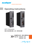
Professional Headend Solutions Operating instructions SAT-TV Transmodulator DVB-S/ -S2 (8x QPSK/ 8PSK) → DVB-C (8x QAM) QAMOS Part No: 5100.01 QAMOS Part N : 5100.01 o SAT-TV Transmodulator DVB-S/ -S2 (8x QPSK/ 8PSK) → DVB-C (8x QAM) SBL Contents 1. Safety and operating instructions ............................................................................................................. 3 2. Device variants ........................................................................................................................................ 3 3. General .................................................................................................................................................... 3 4. Front view ................................................................................................................................................ 4 5. Functional description .,........................................................................................................................... 4 6. Meaning of the LED’s .............................................................................................................................. 4 6.1 LED‘s at the Sat ports ..................................................................................................................... 4 6.2 Device- and channel status LED’s .................................................................................................. 5 6.3 LED‘s at the 10/ 100 Mbit control port ............................................................................................ 5 7. Adjusting by web server .......................................................................................................................... 6 7.1 Network connection to the computer ............................................................................................. 6 7.2 Initial installation using the wizard .................................................................................................. 7 7.3 Settings in basic and expert mode ................................................................................................. 9 . 7.3.1 Menu “Overview“ ............................................................................................................... 10 . 7.3.2 Menu “SAT selection“ ....................................................................................................... 11 . 7.3.3 Menu “Transponders“ ....................................................................................................... 13 . 7.3.4 Menu “Adjustment“ ............................................................................................................ 14 . 7.3.5 Menu “Language“ ............................................................................................................. 16 . 7.3.6 Menu “Service“ ................................................................................................................. 17 . 7.3.7 Menu “Setup“ .................................................................................................................... 17 . 7.3.8 Menu “Level“ ..................................................................................................................... 22 . 7.3.9 Menu “Status“ ................................................................................................................... 22 . 7.3.10 Menu “NIT“ ...................................................................................................................... 23 . 7.3.10.1 Automatic NIT processing ................................................................................. 23 . 7.3.10.2 Manual NIT processing ..................................................................................... 24 . 7.3.11 Menu “LCN“ .................................................................................................................... 25 . 7.3.12 Menu “Program table“ .................................................................................................... 25 . 8. Factory settings ..................................................................................................................................... 26 9. Block diagram ....................................................................................................................................... 27 10. Application example ............................................................................................................................ 27 11. Technical data ..................................................................................................................................... 28 12. Glossary .............................................................................................................................................. 28 13. Bibliography ........................................................................................................................................ 29 14. Document history ................................................................................................................................ 29 2 QAMOS Part N : 5100.01 SAT-TV Transmodulator DVB-S/ -S2 (8x QPSK/ 8PSK) → DVB-C (8x QAM) o SBL 1. Safety and operating instructions When assembling, starting-up and adjusting the modules, it is necessary to consider the system specific references in the manual instruction! The modules may only be installed and started up by authorized technical personnel! There are only permitted the mounting styles indicated in the quick start guide, which is included each module. When assembling the modules into the receiving points, the adherence of the EMC regulations is to be ensured! The assembly and wiring have to be done without voltage. For installation, only the supplied accessories (DIN rail clip with screws and 19“ accessories) may only be used. All active modules may only be operated with the power supply HELIOS. To supply the module only the attached acces- sory cables are used. The mains voltage and the operating voltage of the modules working by DC have to be in complience to the operating parameters described in the technical data. With all work the defaults of the DIN EN 50083 have to be considered! Especially the safety relevant execution of the DIN EN 60728-11[4] is necessary! The unit should be mounted only vertically. The ventilation slots as well as the circulation perforation of the modules must be kept absolutely free. If installed in mounting cabinets a adequate heat circulation must be guaranteed. The mounting in closed cabinets with no air exchange is not allowed! For DIN rail mounting is important to note that between the heat sink and a neighboring building, a distance of 2 cm is required. If the modules mounted on top of each, so to observe a distance of 20 cm from the bottom edge of the top module to top edge of the lower module. For 19“ mounting all devices in the rack must be fitted with 19“ Edge Guide. The sole panel mounting is not enough! Furthermore, the operation of a fully occupied rack is only allowed with an underlying 1-U fan box (at least 3 fans, 176 mm deep)! 2. Device variants QAMOS 5100.01 DVB-S/ -S2 (8x QPSK/ 8PSK) → DVB-C (8x QAM) 3. General The Smart Business Line (SBL) is a modern head end system, that is distinguished by its modular and compact design. A userfriendly operating concept facilitates setup, configuration and maintenance of the system. The QAMOS module converts digital satellite signals into QAM signals to transmit it in cable networks. In this case, up to 8 QAM channels from the available satellite IF signals are generated, which are attached via two inputs. In particular, the internal processing allows the output of DVB signals in full HD resolution. 3 QAMOS Part N : 5100.01 SAT-TV Transmodulator DVB-S/ -S2 (8x QPSK/ 8PSK) → DVB-C (8x QAM) o SBL 4. Front view QAMOS Sat IF input coupler “input 1“ LED input 1 Sat IF input coupler “input 2/ output“ LED input 2/ output 12 VDC Power connections Status LED “POWER“/ “SYSTEM“ Status LED channel 1/ channel 2 Status LED channel 3/ channel 4 Status LED channel 5/ channel 6 Status LED channel 7/ channel 8 Control port (LAN/ WAN) TV-RF OUTPUT Output coupler “input “ Reset button Output coupler “output “ 5. Functional description The Sat-IF signal is fed through 2 inputs or a loop-through input by means of a switching matrix to 8 DVB-S/ S 2 input parts and their QPSK/ 8PSK demodulators. The resulting 8 transport streams are fed a high-performance FPGA. The transport stream processing or filtering, the QAM modulation and the freely adjustable up-converting in the cable network range (45 ... 862 MHz) take place in the FPGA. The eightfold modulator is adjacent channel compatible. A highly-clocked digital to analogue converter (DAC) is responsible for the spectrally pure output of the cable signal. After amplification and sum level adjustment, the cable signal is coupled through a directional coupler to the output jacks. 6. Meaning of the LED‘s 6.1 LED`s at the Sat ports Colour Status Meaning of display green permanently on Sat channel has been configured as input, works properly. off No tuner is locked on this input or port is deactivated (only port “IN/ OUT“). permanently on Sat channel has been configured as output (only port “IN/ OUT“) flashing LNB overcurrent (e.g. by short circuit) and/ or LNB overheated, port is disabled temporarily. amber 4 QAMOS Part N : 5100.01 SAT-TV Transmodulator DVB-S/ -S2 (8x QPSK/ 8PSK) → DVB-C (8x QAM) o SBL 6.2 Device- and channel status LED‘s Designation Colour Status Meaning of display POWER green permanently on Module is on. off Module is off, operating voltage is not applied. SYSTEM green permanently on Module is ready for work. flashing Software Update is running. permanently on Temperature is high, fan is activated. flashing Temperature is critical. The device will no longer ensured or forced shutdown. off Module is not ready for work. green permanently on Channel operates without error. amber permanently on Error warnings, depending on signal: - input and/ or output without sync - input sync, but in bad quality (eg. small blocks in the TV picture) flashing Hardware is faulty. off Channel is off. amber CH 1 ... CH 8 6.3 LED`s at the 10/ 100 Mbit control port Designation/ colour Status Meaning of display Connect LED/ yellow permanently on Network cable is connected. off No cable connection flashing The data exchange. off No data exchange Data LED/ green 5 QAMOS Part N : 5100.01 o SAT-TV Transmodulator DVB-S/ -S2 (8x QPSK/ 8PSK) → DVB-C (8x QAM) SBL 7. Adjusting by web server 7.1 Network connection to the computer System requirements: - PC/ laptop with 10/100 Mbit Ethernet interface - Internet browser (e.g. Windows Internet Explorer), which accept JAVA script. Setup the connection: The QAMOS module has to connected to PC network using an Ethernet cable. The IP address of the QAMOS module is 192.168.1.100 on delivery. If several QAMOS modules should be controlled or adjusted via an Ethernet switch, each module must first be converted individually to its provided IP address within the network! To that the address of the network port on the PC (temporary) must be adapted to the IP address of the QAMOS module (subnet mask: 255.255.255.0, IP address: 192.168.1.XXX, where XXX is not the same as the corresponding value of the QAMOS IP address). After the network configuration of the module(s) the IP address of the control PC is converted to the provided IP address and the modules can be accessed through the browser with their new IP addresses. First appears the login window, if the password and user testing were activated on the setup page (see chapter 7.3.7): After successful registration or successful connection establishment without password (default setting) the start page of the module is charging. Now you can choose whether you want to make the initial installation (using the wizard), or adjust the module in basic or expert mode. In addition, the language selection is possible between German and English top right. 6 QAMOS Part N : 5100.01 o SAT-TV Transmodulator DVB-S/ -S2 (8x QPSK/ 8PSK) → DVB-C (8x QAM) SBL 7.2 Initial installation using the wizard The easiest way to set the QAMOS module is to use the wizard. By pressing the “Initial installation“ button you get to the home page of the wizard. As with any other browser page at the top right hand it can also change the language. First choose the configuration of the system. If the system is equipped with LNB and multiswitch, so you can select the number of feeds on the left. If the system is operated with a Quattro LNB, so you choose from the right side, which satellite level contact with the corresponding input jack. Press the “OK“ button, the corresponding data are loaded and you will be forwarded to the selection of the channel or transponder. In the left column, all available channels are loaded according to the selected satellite from the database. The listing is in alphabetical order, the start of the list can be selected under the list by selecting the first letter. Alternatively, you can also enter a string (e.g. “HD“) in the text box next to the letter sequence. In this case all the channels are listed that contain that search string in their names. 7 QAMOS Part N : 5100.01 o SAT-TV Transmodulator DVB-S/ -S2 (8x QPSK/ 8PSK) → DVB-C (8x QAM) SBL You select the output channel in the selection box right before the transmitter or transponder selection is made. The selection begins with channel S 21 and D 306 (306.00 MHz). But the channels of the entire frequency range of 45 ... 862 MHz can be chosen freely in the selected channel spacing (see chapter 7.3.7). From the channel list on the left you can select by double click the desired program, and thus the entire transponder (which contains this program), which is then transmitted in that output channel. After the selection all channels in this package will be listed in the middle list box.In the upper part the television programs are listed and in the lower part the radio programs. In the upper right list box status information will appear for the selected transponder. In the right list box below there is the list of already selected transponder to the output channel in which they are to be transmitted. In this way, up to 8 transponders per QAMOS module can be selected now to be transferred. First, as the output channel the next higher channel to the last selected program package is offered. But for each packet the output channel can be chosen freely in the total frequency range. If an incorrect selection is made, it can be removed by double-clicking the unwanted selected transponder in the right field . 8 QAMOS Part N : 5100.01 o SAT-TV Transmodulator DVB-S/ -S2 (8x QPSK/ 8PSK) → DVB-C (8x QAM) SBL Clicking on the “OK“ button, the selection is accepted and set in QAMOS module. The browser will be redirected to the home page (see chapter 7.3.1). By a reopening of the wizards left in the navigation tree you can always do a complete reinitialization of the module. The changes will be accepted and set only by pressing of the “OK“ button. Additional or specific settings can be made by using the basic or expert mode. 7.3 Settings in basic and expert mode In both modes, you can set certain parameters of the module or perform configurations on the module or the user interface. The various setting menus can be selected in the navigation tree on the left side. A part of the menu is same in both modes (“Overview“, “Transponders“, “Language“, “Service“, “Wizard“, “Setup“, “Program table“). In the menus “SAT selection“ and “Adjustment“ in the basic mode, a part of the setting parameters are predefined on common values to allowing easier adjustment. In expert mode, all adjustable parameters can then be adapted to the specific requirements of the user. In both menus can be switched via a click box between the basic and expert mode. Additionally in expert mode the menus “Level“, “NIT“, “Status“ and “LCN“ are available. The setting is supported by an online help. Touching the parameters by the mouse in the lower part of the site an orange colored text box appears with explanations for each parameter. By setting in the “Setup“ menu (see chapter 7.3.7) may be selected so that the help appears in the status bar of your browser. If appropriate setting changes in the browser options are necessary. In addition, in the lower part of the navigation tree status information for the module is displayed. By changing the setup menu, the status information can also be moved to the right (see also chapter 7.3.7). All 8 channels are listed individually. A green LED symbol before the “channel ...“ means that both input and output are synchronized and that the channel operates without error. An orangecolored symbol indicates that an error has occurred in that channel. An overview of the status of various parameters of the channel is obtained by double-clicking the corresponding channel. In the browser interface, a status overview appears. 9 QAMOS Part N : 5100.01 o SAT-TV Transmodulator DVB-S/ -S2 (8x QPSK/ 8PSK) → DVB-C (8x QAM) SBL A transparent LED symbol means that the channel is not programmed and set, or the RF output is turned off. Furthermore, we obtain the same way status information about the connected LNB(s) and about system parameters. In this case too an orange-colored LED symbol displays an error state during which a green LED symbol displays error-free working condition. The detailed status information is available by double clicking the name field. The last display point indicates the connection status between the network interface and the module. Green means that the connection is established. A transparent LED light indicates that there is no connection or the connection is failed. Settings with the selection box or input fields are taken over by pressing the “send“ button and stored permanently, and the QAMOS module is set on these values after a restart too. Settings with the click box are usually performed immediately but not stored in memory, so they would be lost on a possible restart of the module. To save these settings the “send“ button must be pressed. 7.3.1 Menu ”Overview” This page provides a status overview of the 8 channels. If a channel is working without errors, “SYNC“ is displayed. If errors occur you will see an “Error“ display. If the RF power is switched off there is no display value behind the respective channel. In addition, under the status window there is the head end display. There all SBL modules are listed, which are in the same network and which have been selected to the head end in the setup menu (see 7.3.7). This is significant because functions over all modules such as the NIT processing can be extended to all components of the head end. The individual components of a head end are listed with their IP address, which is also provided with a link to this address, so you can switch in a simpler form to the next module. If no head end was created, a “Search“ button appears , which forwards to the setup menu and scans the network for other SBL modules. Then all available modules are listed, can be selected and added to the head end. 10 QAMOS Part N : 5100.01 o SAT-TV Transmodulator DVB-S/ -S2 (8x QPSK/ 8PSK) → DVB-C (8x QAM) SBL 7.3.2 Menu ”SAT selection” In this menu you can make the the choice of the satellites and the input configuration of the module. In the left part of the user interface there is the configuration menu of the input part. The switching between the basic mode and expert mode is possible using the click box in the upper right part of the user interface. In basic mode the following settings are possible: IN sat jack 1 (permanent input) LNB control selection: on, off (remote supply off), DiSEqC A, DiSEqC B, DiSEqC C, DiSEqC D SAT selection selection: Astra 19,2° East,low horizontal, low vertical, high horizontal, high vertical Eutelsat 13° East,low horizontal, low vertical, high horizontal, high vertical, Eurobird 9° East high horizontal, high vertical IN/ OUT sat jack 2 Mode selection: not used, input, output LNB control selection: see LNB control sat jack 1 SAT selection selection: see SAT selection sat jack 1 If the 2nd sat jack is configured as a loop-through output, or not used, the associated input configuration parameters “LNB control“ and “SAT selection“ are grayed out and not adjustable. 11 QAMOS Part N : 5100.01 o SAT-TV Transmodulator DVB-S/ -S2 (8x QPSK/ 8PSK) → DVB-C (8x QAM) SBL In expert mode the input settings can be made more detailed and individualized. The setting screen is divided into two sections “LNB Control“ and “Program tables for“, for the two satellite jacks 1 (IN) and 2 (IN/ OUT). The parameters of both sections can be adjusted separately with the “send“ button below and then transferred. If the second sat jack (IN/ OUT) is configured as a loop-through output, or not used, then the input configuration parameters of the LNB control and program table are grayed out and not adjustable. selection of sat jack 1 (IN) and 2 (IN/ OUT) Mode* LNB control DiSEqC Satellite** Tonburst 22 kHz Voltage selection: not used, input, output selection: on, off (remote supply off completely) selection: on, off selection: A, B, C, D selection: off, A, B selection: on, off selection: 13 V, 18 V * ** only for sat jack 2 (IN/ OUT) adjustable only adjustable, if DiSEqC is on Satellite selection: Astra 19,2° East, Eutelsat 13° East, Eurobird 9° East Band selection: Low, High Polarization selection: vertical, horizontal In the right part of the browser interface there is a table of available transponders, which is loaded according to the selected satellite, band and polarization. The transponders are listed by name, downlink frequency, sat-socket assignment and contained programs. This is based on an internal database with the current assignments of the satellite transponder positions Astra 19.2° East, Eutelsat 13° East and Eurobird 9° East. If the transponder allocations should change, you can customize this table and even edit. By doubleclicking the relevant transponder number you entry into the edit menu and can change the data accordingly. Existing entries can be changed or new ones are attached. By clicking on the appropriate box the program list of the transponder can be deleted and changes or additions can be stored into the database permanently. If the box „Save entries“ is not clicked, the changes will remain only as long as the user interface is open.With the next start of the user interface the changes are lost. In this simple way, the program data is kept up to date. 12 QAMOS Part N : 5100.01 o SAT-TV Transmodulator DVB-S/ -S2 (8x QPSK/ 8PSK) → DVB-C (8x QAM) SBL 7.3.3 Menu ”Transponders” In this menu, the transponder selection, and so the program selection too, is done for all output channels. The user interface is divided into three tables. To the left there is the list of the selectable satellite transponders. This list results automatically from the selected satellite setting (see chapter 7.3.2). The transponders are listed with their name, the downlink and the input allocation. In the middle there is the current transponder allocation of the 8 channels, where on left side there is the selected satellite transponder and on right side there is the corresponding output channel. Outside right next to the output channel there are two selectors: with the first the RF signal of the respective channel is turned on or off, with the second you can select one of the 8 channels for setting. In the right table, the television and radio programs, that are transmitted on the selected channel, are listed with their name and service ID. To make changes, you must first select the desired channel. This is done either by clicking the appropriate selector outside right next to the output channel in the middle of the channel list or by clicking on “Channel“ in the navigation tree on the left side, which is listed as a point of the menu “Transponders“. If you want to change the input settings, one marked the first desired transponder with a single click in the left table. By pressing the button “>“ left next to the input transponder in the middle of this overview, the transponder is adopted into the channel. At the same time the channel assignments associated with the service ID and filter-click box is listed in the right table. With this box you can select which channels of the transponder are transmitted and which are filtered out of the package. To transmit a program, it must be selected in that box. The program‘s filter function is only available in expert mode. If you want to change the output channel, so you click on the select box in this channel and selects the desired output channel. On double assignments within these 8 channels is called attention to this automatically! Clicking on the “Send“ button, the settings are taken and stored. 13 QAMOS Part N : 5100.01 o SAT-TV Transmodulator DVB-S/ -S2 (8x QPSK/ 8PSK) → DVB-C (8x QAM) SBL 7.3.4 Menu ”Adjustment” In this menu, the settings of the module are made. The basic mode is very simple. In this mode you can only adjust the output level for all 8 channels in a range from 62 ... 82 dBµV. All other settings are set to the default values and are listed under the level setting. In expert mode, however, each channel can be adjusted individually according to individual requirements. The channel selection may be either left in the navigation tree or above the set-up tables. 14 QAMOS Part N : 5100.01 o SAT-TV Transmodulator DVB-S/ -S2 (8x QPSK/ 8PSK) → DVB-C (8x QAM) SBL The following parameters are adjustable: Input input parameters of the channel Transponder Input Downlink Symbol rate name of the transponder, editable selection of the satellite input: IN, IN/ OUT input in MHz input in kSps Output output parameters of the channel Frequency input Output frequency Output level offset QAM constellation Symbol rate RF signal Spectrum position Mode QAM standard selection: channel, frequency * selection from channel table/ input in kHz * display of the level offset ** selection: 16, 32, 64, 128, 256 QAM input in kSps selection: on, off selection: normal, inverted selection: Transcoder, Test signal, Test level DVB-C/ ITU-T J.83 Annex A (fixed) If selected at the frequency input “channel“, so you can select the output frequency in the pre-selected channel spacing (see chapter 7.3.7). If, however, at the frequency input “frequency“, then the output frequency is selectable in kHz steps. ** Adjustment of the offset of each channel to the basic level, see chapter 7.3.7 * Transport stream processing SDT processing selection: on, off Original network ID adjustment range: 0...65535 Original transport stream ID adjustment range: 0...65535 NIT processing Network name Network ID selection: on, off name of the network (max. 30 characters) adjustment range: 0...65535 CAT processing CA system ID Operator ID selection: on, on with CA filter, off adjustment range: 0...65535 adjustment range: 0...65535 LCN processing Standard SD selection: on, off selection: IEC 62216, NorDig (V1) If the LCN processing was turned on, you can switch by pressing the “Editor“ button to LCN editor to make the necessary adjustments (see chapter 7.3.11). 15 QAMOS Part N : 5100.01 o SAT-TV Transmodulator DVB-S/ -S2 (8x QPSK/ 8PSK) → DVB-C (8x QAM) SBL In the table “Program filter“,the program filter function of the channel can be executed. If the program filter is turned off, all programs of the received transponder can be transmitted. At the left of the overview all programs with the associated service ID are listed. To the right is one click box to tag the program. In the right part of the overview there is the selector of the filter activation at the top. In the second box “Filter mode“, you choose whether the selected channels are blocked or allowed to pass. In the box “Information of other transponders“, it may be selected if additional information about SDT data from other transponders, which are transferred in the data stream under the “Other“, are filtered out or are transmitted. Possible EPG information from other transponders, which can also be transferred under the “Other“ in the data stream, are always transmitted with! The 3 buttons right below are used to simplify the selection of the program list. 7.3.5 Menu ”Language” In this menu, the changeover of the user interface language is executed. You can choose between German and English. The transition can be made either to the left in the navigation tree in the subtree of the point “language“ or top right of the language selection box. 16 QAMOS Part N : 5100.01 o SAT-TV Transmodulator DVB-S/ -S2 (8x QPSK/ 8PSK) → DVB-C (8x QAM) SBL 7.3.6 Menu ”Service” In this menu you will find all information about the service for the QAMOS module. There are given the BLANKOM service hotline and the service email address. In addition, the implemented operating instructions may be called as a PDF. If there is an Internet connection the BLANKOM homepage can be started. There, the latest software release or descriptions are available. Finally, the currently installed software release appears. 7.3.7 Menu ”Setup” In this menu, various administrative and system settings are made. 17 QAMOS Part N : 5100.01 o SAT-TV Transmodulator DVB-S/ -S2 (8x QPSK/ 8PSK) → DVB-C (8x QAM) SBL Specifically, the following can be configured: GUI settings Help information within the status line of the browser By default, the online help is displayed in an orange text box at the bottom of the page. If you click this option, the help texts are displayed in the status bar of your browser. Depending on your browser sometimes has to be allows such use in the browser settings. Display all system files The default is, that the system files can be subjected to upload or download as a package under “Backup“ in the submenu “System administration“. If you click on this box, the system files are listed individually and can be individually subjected to an up- or download. Use basic mode for SAT selection Switching between basic and expert mode of the satellite settings (see also chapter 7.3.2) Use basic mode for adjustments Switching between basic and expert mode of the channel settings (see also chapter 7.3.4) Display top line register By default, the registers are shown in the upper part of the user interface, to move more quickly to the most frequently used menus. By removing the box marking the registers are hidden. Display start page The default is to start with the menu selection by the command buttons after every restart of the user interface (see chapter 7.1), where you can select the desired setup menu. If this item is disabled, this page will be skipped and you reach instantly the “Overview“. Display status on right By clicking on the box, the status of the channels or the system is shifted to the right of the user interface. Output frequency raster With this selection box you can set the output channel spacing, which is pre-set for adjustment of the QAM channels. To choose there are the standard B/G raster, the standard G raster (continuous 8 MHz) and the channel spacing of the cable company Kabel-Deutschland-Gesellschaft (KDG). Activate user and keyword check This selection is only available if you are logged in as administrator. If the box is disabled, the log-in is skipped after each GUI reboot. Otherwise, user login and password are required (see chapter 7.1). SBL head end All SBL modules, which are located in the same network, are listet. By pressing the “Search“ button the list is updated. All marked modules belong to the head end and are displayed on the “Overview“ page Oscillator frequency of LNB Low High Changeover frequency (Downlink) 18 input of the Lo-frequency for receiving of the low band (in MHz) input of the Lo-frequency for receiving of the highband (in MHz) input of the frequency for point of entry from the low into the high band (in MHz) QAMOS Part N : 5100.01 o SAT-TV Transmodulator DVB-S/ -S2 (8x QPSK/ 8PSK) → DVB-C (8x QAM) SBL System administration The default is displaying of the shortened list of files (top). Backup Here the system files can be loaded or saved as a package (except logbook. txt and status.xml). Thus, it is possible, for example in a simple way to copy the system files from a QAMOS module to another. If under “GUI setup“ “Display all system files“ is selected, the system files can also be loaded or saved separately (see figure below). Moreover, additional system files can be added (e.g. other satellite assignments). Software Update By clicking the “Load“ button, the internal software components can always be brought up to date. Pressing the button “View logbook“ leads to an overview, in which all the processes have been documented since the start of the GUI. Each operation is listed by date, time and description. If operations have been executed, the logged on user, who initiated the action, is saved too. By pressing of the “Delete“ button all entries are deleted, when you are logged in as administrator. System Location Logout Default Reboot In this field a name for the QAMOS is be made to identify the module easily. This name appears on the top right of the website under the langua- ge selection box and is provided via SNMP with the question of the field: Iso(1).org(3).dod(6). internet(1).mgmt(2).mib.2(1).system(1).sysLoca- tion(6). restart the user interface delete the settings and reset to default values (including IP address), available only if you have logged in as administrator restart of the QAMOS module Date and time Clicking on the “Set“ button, the date and time will be set to that of the PC. 19 QAMOS Part N : 5100.01 o SAT-TV Transmodulator DVB-S/ -S2 (8x QPSK/ 8PSK) → DVB-C (8x QAM) SBL Enabling of In this field, possible software options for the QAMOS module can be enabled. The registration code must be entered in the input field and by pressing the “Send“ button the option will be activated. Web server This setting appears only when you are logged in as administrator, so also has the authority to make administrative changes. Beginning with release 2.0 the QAMOS supports the DHCP functionality. There DHCP-Client is factory default. After an update from a release 1.x to a release 2.x the DHCP support is off. Note, that after each factory reset the QAMOS is set “DHCP-Client“. If the DHCP functionality is set to “Off“, in the appropriate fields the IP number, subnet mask and gateway can be manually entered and then the settings of the QAMOS module are adapted to the network. If the module is set as “DHCP-Client“, so it is automatically obtained on the network an IP address from the DHCP server. The manual network settings are grayed out and are therefore disabled. By pressing the “Info“ button the automatically assigned network configuration of the module is displayed. If the module is set as “DHCP-Server“ note, that the IP address 192.168.1.100 should not be set. If you select this address, you will get an error message. In addition to the IP settings you can configure the DHCP range from which the IP addresses of the connected clients are assigned. The address range must match the address range according to IP address and subnet mask of the server and should not be too small. The default is the area 192.168.1.1 to 192.168.1.99. Along with the DHCP server will also set up a local DNS (Domain Name Server). To use it in full extend a connected PC/ laptop must be configured as a DHCP client. Especially on Windows is to be noted that not only the IP address, but also the DNS server address automatically is to relate. If the module is configured as a DHCP server or client and the client has received an IP address successfully, so the module can be accessed via a web browser with a name. This name is composed of the prefix “sbl“ and the device number that is printed on the back of the module and on the packaging. For example, the device with the number 0123456 is be called under “sbl0123456“. Should there be problems with it among the local network conditions, so in these cases the domain is to add when you call. In the case that the above module is configured as a server, the call using the domain is then “sbl0123456.sbl“. If another DHCP server is used, for example, the server of the home network, ask your administrator for the domain name. An example of the simplification of the configuration or operation of the head end via DHCP, is, that an SBL module is as a server, the remaining modules and the connected PC/ laptop are configured as a client. By calling the browser “dhcp.sbl“ the surface of the server module is loaded. If not already done so, now the head end can be read. So all connected components are found and listed. The head end can now be stored in the “Setup“ menu under the item “System administration“. In the head end overview can be changed quickly to the user interface of any other module by selecting the respective modules links. 20 QAMOS Part N : 5100.01 o SAT-TV Transmodulator DVB-S/ -S2 (8x QPSK/ 8PSK) → DVB-C (8x QAM) SBL SNMP option The SNMP adjustment is only available after the “SNMP“ option was enabled (see chapter “Enabling of“). In the first section, the SNMP functionality, including the sending of traps is enabled or disabled with the “Mode“ selection field. With the selector “Version“ you can select the SNMP version (version 1, 2 or 3). In the two boxes below it, the communities for versions 1 and 2 are given separately for reading and writing via SNMP. In version 3, these two fields are disabled. There, all registered users of the module (see menu “Passwords“) have an automatic read access to SNMP. The write access can be enabled or disabled for each user by clicking the SNMPclick box in the “Passwords“ menu. By clicking the “MIB“ button the MIB of the module is generated and can be stored. In the second section the trap settings are done. First, the trap version is selected: V1 trap - normal traps according SNMPv1 with specified community V2 trap - normal traps according SNMPv2 with specified community V2 inform - sends information traps according SNMPv2 and waits for an acknow- ledgment V3 trap - normal traps according SNMPv3 V3 inform - sends information traps according SNMPv3 and waits for an acknow- ledgment The community can be configured for traps of SNMP versions v1 and v2. User/ password and use the network MAC address as the engine ID can be configured for traps of SNMP version v3. These settings must correspond with the configuration of the trap receiver, so traps are successfully transferred. For this purpose a test trap can be sent by clicking the button “Test“ to test the transmission of traps. If a test trap triggered, all pre-preserved traps discarded. There up to 256 IP addresses to receive the traps can be created or enabled. These are listed under “Receiver IP“. Below, the events can be configured, whether and partly with what thresholds they should trigger traps. There are three ways to configure a trap: - without parameters, e.g. fan on/ off - with a freely selectable parameters for a medium priority - with a selectable parameter from a list for a medium priority References and notes: All users are supposed to work with SNMPv3 must use passwords with at least 8 characters. For SNMPv3 the SBL supports only the authentication password, not the privacy password. The SBL only supports the MD5 algorithm for authentication password in SNMPv3.. Information traps are specific traps that are possible up to SNMPv2. If there is no acknowledgment of the receiver, the transmitter attempting to transmit later again, until the confirmation is received. A SBL-module holds up to 256 before information traps that could not be sent successfully. If there are more waste traps, the earlier traps are discarded and noted in the logbook as having failed. A successful sent trap is also registered as such in the logbook. In case of power failure or reboot of the module reproached traps are lost. Details may be found in the help text for each event. The critical priorities are each covered with fixed values that can not be changed. If the web site of QAMOS module is open, no changes are possible via SNMP. Passwords Again, this setting appears only when you are logged in as administrator, giving it the authority to make administrative changes. In addition it must be clicked the box “User and keyword check“ in the submenu “GUI settings“. The user ID and password for the administrator can be set in then the first line. The fixing of up to 8 user identification and passwords-is possible. The limitations of user rights exist only in the fact that they are not authorized to change web server settings, user rights and password changes and default settings. The default password for the admin is: 1111 and for the users: 0000 If the SNMP option is enabled, after each user appears an SNMP-click box. By clicking on the box, the writing rights for individual users can be awarded for the SNMP version 3 (see also section SNMP option). 21 QAMOS Part N : 5100.01 o SAT-TV Transmodulator DVB-S/ -S2 (8x QPSK/ 8PSK) → DVB-C (8x QAM) SBL 7.3.8 Menu ”Level” This menu is only available in expert mode. The standard level can be set for all 8 channels (i.e. in common) in the range of 62 ... 82 dBµV in the top selection box. Below it each channel can be set individually with an offset of +3 ... -6 dB in 0.5 dB steps. The three lower buttons are used to simplify the offset level setting if you want to perform same adjusting for all 8 channels. With the left button the offset for all 8 channels is increased by 0.5 dB, decreased with the right button by 0.5 dB. The offset is set for all 8 channels to 0 dB with the middle button. 7.3.9 Menu ”Status” The status overview of QAMOS module is only available in expert mode. It presents an overview of the status of the various components per channel, which is updated every 5 seconds. It lists only the current values, the naming of the parameter appears in the help box in the lower part of the user interface or in the status bar of the browser (as adopted configuration), if you approach the mouse cursor to the parameter. 22 QAMOS Part N : 5100.01 o SAT-TV Transmodulator DVB-S/ -S2 (8x QPSK/ 8PSK) → DVB-C (8x QAM) SBL 7.3.10 Menu ”NIT” This menu is only available in expert mode, too. The NIT processing for all to a head end associated QAMOS modules can be done in 2 ways: as an automatic or manual NIT processing. The simplest and by installation and support expense safest way is the automatic NIT processing. The precondition is that all to the head end associated QAMOS modules have a different IP address and an Ethernet switch must be connected to each other so that the data exchange can take place automatically. The NIT settings must be made here only in one QAMOS module of the head end and after confirmation they are automatically included of all other modules. The Ethernet connection among each other is not necessary for the manual NIT processing, but the settings must be made or maintained separately in each module of the head end, which means a much higher expense. To start the NIT processing it is first necessary to put together the head end in the user interface. At first in the menu “Setup“ (see chapter 7.3.7) at the point “SBL head end“ the “Search“ button is to press. Alternatively, you can press the “Read“ button in the menu “Overview“ (see Section 7.3.1) under the item “SBL head end“ overview in the case of factory setting. First all QAMOS modules are listed that are within the network. If there is no network connection between the QAMOS modules (the case of manual NIT processing), here only this one QAMOS module appears on which the settings are being implemented. The next step, all QAMOS modules are selected, which should belong to the head end (in the case of the manual NIT processing the module itself) and the selection has to be confirmed with the “send“ button. In the case of an automatic NIT distribution now the data of all selected modules are exchanged. Further adjustments must be performed only in one module and be adopted by all the other automatically. In the case of a manual NIT processing this step must be implemented in each module of the head end. The data of the other modules must be taken manually in each module, as explained in subsequent chapters. 7.3.10.1 Automatic NIT processing As explained above, all QAMOS modules of the head end must be connected over an Ethernet switch for automatic NIT processing. The creation or editing of the NIT settings must only be done on one module of the head end and is then applied from all other modules automatically. It presents the last created NIT table of the whole head end with continuous listing of the following parameters: transport stream ID, original network ID, output frequency in kHz, QAM constallation, symbol rate in kSps, insert and delete fields. A characteristic of the automatic NIT processing is that all channels of the QAMOS modules are listed in frequency-ascending blue colored table cells. If the first time an NIT is created, a list appears with no table entries. The loading or update of the NIT is then in edit mode. By clicking the “Export“ button, the NIT of the head end is saved as a .xml-file on the PC. In the editing mode this settings can be changed. By clicking on the box “Edit“ in the top right of the user interface you can switch to edit mode and edit the NIT entries. With the “+“ button, an entry will be added. The settings of the last table entry are accepted and must be adjusted accordingly. With the “Delete“ button the table entry is removed. Also in this mode, you can save the NIT of the module with the “Export“ button as .xml-file on the PC. By clicking the “Import“ button, another NIT can be added, which was previously stored as a .xml file on the PC. In this way its easy possible to create a NIT of a system with multiple QAMOS modules. In the NIT processing all the selected table entries are included. In the lower part of the GUI it appears additionally an overview of the settings for the NIT processing of all the channels of the head end. Here the NIT transmission per channel can be switched on or off easily and the network name and network ID can be changed. The settings are identical to the section “Transport stream processing” in the setup menu (see chapter 7.3.4). If all settings have been made, with pressing the “send“ button this NIT is automatically stored in all other QAMOS modules of the head end. 23 QAMOS Part N : 5100.01 o SAT-TV Transmodulator DVB-S/ -S2 (8x QPSK/ 8PSK) → DVB-C (8x QAM) SBL 7.3.10.2 Manual NIT processing After the preparation or initializing of the NIT, described in 7.3.10, first it must be called the edit mode of the NIT in each QAMOS module of the head end, readed the NIT of the module and stored on the PC by clicking the “Export“ button. Then you append the NIT of the other QAMOS modules, which belong to the head end, by repeatedly pressing the “Import“ button in edit mode. As opposed to the automatic NIT processing here appear the added tables in white color. After the appropriate selection of channels of the NIT and any change in the network name or network ID the NIT of this QAMOS module is stored and transferred by pressing the “Send“ button. To facilitate the setting of all other QAMOS modules the head end, this head end NIT can be stored in the PC by clicking the “Export“ button. Now all the other QAMOS modules of the head end have called successively, these stored NIT loaded by pressing the “Import“ button and then adopted and saved by pressing the “Send“ button. For changes of the NIT is to be noted that these changes must be made in the NIT of each module. It is therefore recommended to prefer the automatic NIT processing of the manual NIT processing. 24 QAMOS Part N : 5100.01 o SAT-TV Transmodulator DVB-S/ -S2 (8x QPSK/ 8PSK) → DVB-C (8x QAM) SBL 7.3.11 Menu ”LCN” The LCN editor is only available in expert mode. The allocation of a logical channel number (LCN) is a service that allocates a serial number to each TV program in all the channels, which are enabled for this service. If the set-top box supports this service at the subscriber, the TV programs are offered in the order established by program numbers. To use this service, the LCN processing of all appropriate channels must be turned on. Then you can set the program order. It should be noted that the numbering is done separately for HD and SD programs. When you first load the LCN editor there in the left table cell, all the transferred services of the channels are listed that were marked in the lower right table for LCN processing. TV channels are already pre-selected, separated for HD and SD programs, all services are still provided with the number 0. You can now assign the LCN for the selected program automatically by pressing the “OK“ button in the right box “automatic numbering“, starting with the number registered there. The numbers can also be selected manually: individually by clicking on the corresponding box in the left table, or all programs of a type by pressing the “Enable all“ button. The numbering itself is performed again by pressing the “OK“ button. In order to reverse the numbering for HD or SD programs, one selects the corresponding LCN type in the right table field and press the “Reset all (LCN = 0)“. 7.3.12 Menu ”Program table” The program table gives an overview of the channel allocation of the QAMOS module. The overview begins with the output frequency and output channel identifier for each transmission channel. Under them all TV and radio programs are listed, which are transmitted in this channel. 25 QAMOS Part N : 5100.01 o SAT-TV Transmodulator DVB-S/ -S2 (8x QPSK/ 8PSK) → DVB-C (8x QAM) SBL 8. Factory settings A short pressing of the reset button on the front of the module causes a reboot, ie it will restart the module and all stored values are adjusted. If the module is to be reset to factory settings, the reset button must be pressed so long to keep up until the “POWER“ and “SYSTEM“ LED will illuminate green permanently. This process takes about 15 seconds. In this case the module is set to the following: Input parameters Output parameters Channel settings Setup settings Network settings 26 QAMOS Part N : 5100.01 SAT-TV Transmodulator DVB-S/ -S2 (8x QPSK/ 8PSK) → DVB-C (8x QAM) o 9. Block diagram 2x 8x SAT 8x Tuner 8x 8x Demod. IQ 2x LNB-Power 8x TS Stratix IV FPGA Eth. CPU TSProc. NIOS SDRAM 8x MOD UPC DAC DDR 2 FLASH 10. Application example Application example Conversion of 24 transponders into DVB-C (256 QAM) Astra 19,2° Eurobird 9° Multiswitch to the net/ distribution DVB-S/-S2 DVB-S/-S2 DVB-S/-S2 QAMOS QAMOS QAMOS 8x QAM 8x QAM 8x QAM HELIOS SBL 5150 SBL 5100 SBL 5100 SBL 5100 27 SBL QAMOS Part N : 5100.01 o SAT-TV Transmodulator SBL DVB-S/ -S2 (8x QPSK/ 8PSK) → DVB-C (8x QAM) 11. Technical data SAT-IF input Frequency range Frequency step AFC range AGC level range Connector Through loss Impedance 950...2150 MHz 1 MHz ± 3 MHz (SR < 10 MSps) ± 5 MHz (SR ≥ 10 MSps) 64 ... 94 dBμV F socket ≤ 3 dB 75 Ω DVB-S demodulator (QPSK) Symbol rate Code rate (Viterbi) Roll off Signal processing 1…45 MSps 1/2, 2/3, 3/4, 5/6, 7/8 35 % EN 300 421 [1] RF output Output frequency range Tuning step Max. output level Total level settings Individual level settings (offset) Channel allocation Connector Impedance Return loss Signal quality MER Shoulder attenuation Spurious 45...862 MHz max. frequency stability Output level stability DVB-S2 demodulator (QPSK, 8PSK) Symbol rate QPSK 2…47 MSps 8PSK 2…31.5 MSps Code rate (LDPC) QPSK 1/4, 1/3, 2/5, 1/2, 3/5, 2/3, 3/4, 4/5, 5/6, 8/9, 9/10 8PSK 3/5, 2/3, 3/4, 5/6, 8/9, 9/10 Roll off 20, 25, 35 % Signal processing EN 302 307 [2] QAM modulator Input data rate Symbol rate QAM modulation QAM constellation Roll off Interleaving Forward error correction/ FEC PSI-/ SI processing Zero stuffing Signal processing Test signals: QAM test signal Measurement signal Operating parameters Voltage/ current Residual ripple of the supply voltage Environmental conditions Temperature range Temperature range for data keeping Relative humidity Method of mounting Location of mounting max. 78 Mbps acc. adjustment symbol rate & QAM constell. 1.0-7.2 MSps DVB-C 16; 32; 64; 128; 256 15% Conv. I=12 Reed Solomon/ (204, 188.8) disconnectable continously EN 300 429 [3] according adjustment symbol rate & QAM constellation unmod. carrier (signal level) 45 ... 862 MHz 125 kHz 85 dBμV (per channel) 62 ... 82 dBµV (1 dB steps) +3 ... -6 dB (0.5 dB steps) adjacent channel ability F socket 75 Ω ≥ 18 dB 45 MHz - 1.5 dB/ octave ≥ 45 dB ≥ 53 dB ≥ 60 dB 30 kHz ± 0.5 dB 12 V ± 0.2 V/ max. 2.6 A 10 mVpp -10 ... +55 °C 5 ... 45 °C ≤ 80 % ((non condensing) vertical splash-proof and drip-proof Miscellaneous Dimensions (l x w x h) Weight 46 x 262 x 167 mm 1,190 g Delivery content 1x supply cable 1x network cable 2x F connecting cable 140 mm 2x terminating impedance 1x DIN rail clip 1x mounting accessories 12. Glossary 8PSK AFC AGC BER BW CA CAT DVB EIT ETSI FAT FEC FPGA GUI HTTP I/Q ID IF IIC IP LDPC LED MAC MER MIB 8 Phase Shift Keying Automatic Frequency Control Automatic Gain Control Bit Error Ratio Bandwidth Conditional Access Conditional Access Table Digital Video Broadcasting (-C Cable, -S Satellite, -S2 Satellite 2, -T Terrestrial) Event Information Table European Telecommunications Standards Institute File Allocation Table Forward Error Correction Field Programmable Gate Array Graphical User Interface Hypertext Transfer Protocol In-phase/ Quadrature-phase Identifier Intermediate Frequency Inter-Integrated Circuit (I²C bus, data bus within device) Internet Protocol Low Density Parity Check Code Light Emitting Diode Media Access Control Modulation Error Ratio Management Information Base 28 QAMOS Part N : 5100.01 o SAT-TV Transmodulator SBL DVB-S/ -S2 (8x QPSK/ 8PSK) → DVB-C (8x QAM) MPEG MPTS NIM Nios NIT PAT PCR PID PMT PSI QAM QPSK RF SDT SI SNMP SPTS TS Moving Picture Experts Group Multi Program Transport Stream Network Interface Module Produktname für einen Prozessor Network Information Table Program Association Table Program Clock Reference Program Identifier Program Map Table Program Service Information Quadrature Amplitude Modulation Quadrature Phase Shift Keying Radio Frequency Service Description Table Service Information Single Network Management Protocol Single Program Transport Stream Transport Stream 13. Bibliography [1] EN 300 421: Digital Video Broadcasting (DVB): Framing structure, channel coding and modulation for 11/ 12 GHz satellite services [2] EN 302 307: Digital Video Broadcasting (DVB): Second generation framing structure, channel coding and modulation systems for Broadcasting, Interactive Services, News Gathering and other broadband satellite applications [3] EN 300 429: Digital Video Broadcasting (DVB): Framing structure, channel coding and modulation for cable systems [4] EN 60728-11: Cable networks for television signals, sound signals and interactive services Part 11: Safety (IEC 60728-11:2005); German version EN 60728-11:2005 [5] EN 50083-2 : Cabled distribution systems for television and sound signals. Electromagnetic compatibility for equipment; EN 50083-2:2001 [6] RFC 1157 Request for Comments (RFC): RFC Database URL: Http://www.rfc-editor.org/rfc.html 14. Document history Version Date Modification Author 1.00 16.11.2010 basic document Häußer 1.01 01.12.2010 first revision Häußer 1.02 15.02.2011 revision Häußer 1.03 17.03.2011 revision chapter 7.3.10 Häußer 1.04 19.01.2012 insert changes of software release 2.0 Häußer Options available upon request! Subjects to changes due to technical progress. BLANKOM Antennentechnik GmbH Hermann-Petersilge-Straße 1 • 07422 Bad Blankenburg • Germany • Telefon +49 (0) 3 67 41 / 60-0 • Fax +49 (0) 3 67 41 / 60-100 29 Declaration of Conformity The Manufacturer BLANKOM Antennentechnik GmbH ∙ Hermann-Petersilge-Str. 1 ∙ 07422 Bad Blankenburg ∙ Germany herewith declares the conformity of the product Product name: SAT-TV Transmodulator Type: QAMOS Product number: 5100.01 according to the following regulations EN 50083-2 EN 60728-11 (as far as relevant) and additional device-specific regulations, enclosed above, which this product is subjected to. Date: 16.11.2010 Signature: (Managing Director) 30