1
Creative technology made by rbr
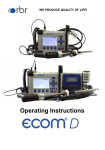
Operating Instructions
Index
Important hints
1. Instrument design
1.1. Basic module
1.2. Control module
1.3. Accessories
2. Gas cooler (option) / Version ecom-J2K-P
3. Power supply
4. Radio communication basic/control module
5. Data record
5.1. Internal memory
5.2. Multi Media Card
6. Instrument switch on
7. Input or selection of combustion plants
8. Flue gas analysis
8.1. Gas analysis
8.2. CO mesurement (gas path check)
8.3. O2 check
8.4. Draught measurement
8.5. Soot dot...Oil trace
8.6. Measurement record and printout
8.7. Printout ecom-J2K
9. Adjustments
10. Control
11. Data processing
11.1 Internal memory
11.2 Multi Media Card
12. Fault diagnosis
13. Maintenance tips
14. Technical data
Page 2
Page
3
4
5
6
8
9
10
11
11
12
14
16
19
20
20
21
23
24
25
27
27
29
30
32
34
ecom-J2K
Important hints
The ecom-J2K meets the requirements of DIN
EN 50379 part of 2.
The ecom-J2K may not be used for
continuous emission control!
Following minimum times must be kept, in
order to receive correct measured values:
-1 min. to calibrate the sensors at fresh air
-2 min. for stable measured values
The following substances impair the working
of the instrument:
-Cleaning agents
-Degreasers
-Wax polishes
-Adhesives
-Formaldehyde
Adjustments at burners and boilers should be
made only by specialists, who are familiar with
those installations!
ecom-J2K
Page 3
1. Instrument design
Connection
gas hose
1.1. Basic module
Condensate trap with
fine dust filter
Control module
(see next page)
Optical flow control
Connection
draught
Cable socket by
wire transfer basic/
control modules
Connection
pressure
ON/OFF
switch
Connection gas
temperature
Connection
sucking
temperature
Control LED´s
(see chapter 10.)
Front view
ecom-J2K
Integral printer
Fixation
3-chamber hose
Radio temperature
sensor (option)
SO2/NOx filter
for CO sensor
Cover battery
compartment
Cover sensors
compartment
Fixation gas
probe
Loading socket
(by versions with external
loading unit only)
Rear view
ecom-J2K
Connection condensate
evacuation
Page 4
Connection mains
power plug
(by version with internal
loading unit only)
ecom-J2K
1.2. Control module
Slot for Multi
Media Card
Graphics display
Connection
keyboard
Connection
sucking
temperature
Socket for connection
cable by wire transfer
Keyboard control module
basic/control modules or
for RS 232 cable
Function keys
(function shown on display)
Measurement
values
recording
Display
backlit ON/
OFF
Cursor keys
(Up/Down/Right/
Left/Scroll)
ESC key
(quit/
escape menu)
Switch ON/OFF
control module
ecom-J2K
OK key
(confirm
selection)
In the input mode, the
keys are used for
numerical inputs.
Print key
(access to printing
menu)
Page 5
1.3. Zubehör ecom-J2K
Transport case
Item nr.:
60012
Transport case
(smal)
Item nr.:
60127
Carrying bag
„Rucksack
version“
Item nr.:
30002117
Carrying bag
Item nr.:
30002113
Add. keyboard
Item nr.:
1050011
Magnet fixation
for control unit
Item nr.:
51149
Multi-Media-Card
128 MB
Item nr.:
53656
Data interface DAS-Software
Item nr.:
32000024
Data interface giant display
Item nr.:
1040030
Data cable
Item nr.:
52182
1050012 (with amplifier)
without illustration
NOx hose
(soot probe)
Item nr.:
10176 (3,5 m)
30001187 (5 m)
NOx hose (probe without
soot measurement)
Item nr.:
10178 (3,5 m)
10185 (5 m)
Page 6
ecom-J2K
Filtering case
(solid
combustibles)
Item nr.:
55810
Gas washing bottle
(only with
peltier cooler)
Item nr.:
5044041 (Tasche)
5044042 (Koffer)
Soot pump kit
Item nr.:
50538
T-room stick
Item nr.:
51446
Cable control - basic module
1,5 m lang Item nr.: 1040021
3,0 m lang Item nr.: 1040022
5,0 m lang Item nr.: 1040023
10,0 m lang Item nr.: 1040024
20,0 m lang Item nr.: 1040025
without illustration
ecom-J2K
Page 7
2. Gas cooler (option) / Version ecom-J2K-P
Peltierelement
GasOutlet
warm
cold
Level control
Fan
GasInlet
Condensate
evacuation
Due to the power supply need of the gas cooler, it is
only available with mains power!
Exhaust gas with a temperature over the steam dew point (35 to
65 °C) is flown spiral via a long gas path thru a surface coated metal
body with good thermal conductivity. The gas radiates its heat to this
metal body. A PELTIER element (semiconductor cooling element) flown
by a continuous current is thermically connected with this body and
with a second metal body with cooling ribs and ventilation slots. The
flow thru the PELTIER element creates a heat transfer from WARM to
COLD, drains the heat of the metal body flown by gas and conveys it
to the outer cooling body. This heat is conveyed thru a vertical forced
ventilation to the surrounding air.
The condensation issued by the heat loss of the gas drops in a
receptacle and is pumped out on request (either by the user or due to
the level monitoring) by a periodically working hose pump.
The sucking capacity of the gas conveying pump avoids a sufficient
dwell time of the gas with the condensate, so that wash out reactions
(NO2+H2O > H2NO3) do not take place.
At the cooler outlet the gas has a temperature of ca. 5 °C with a relative saturation of nearly 100 % relative humidity (corresponds to a
water vapour content < 7 g/m3).
Page 8
ecom-J2K
3. Power supply
Used accumulators can be returned to us or brought to
recycling stations of public waste disposal companies
respectively accumulators selling stores!
The basic module of the ecom-J2K is delivered either with external or
with internal loading unit (depending on features selected). In both
cases the instrument can be operated upon a longer time period with
the internal accumulator (6 V; 7,2 Ah). Connecting the external or the
internal charging unit to mains power is only compulsory to recharge
the accumulators and to operate the Peltier cooler and the heated
pistol grip probe.
The accumulators should be recharged when the instrument shows a
corresponding message (acoustical warning and display
information). The accumulators loading stand can be checked,
looking at the voltage information on the display (menu "Control").
The accu warning is activated when the value „ACC.B“ is smaller
than 6 V.
By 5,8 V the power operation via accus is no more possible. The
instrument must be further powered via external or internal charging
unit.
Never use batteries to operate the
control module of the ecom-J2K!
The control module of the ecom-J2K is powered by 3 nickel-metalhydride accumulators (type AA). In case of need, the accumulators
can be recharged by docking the control module to the basic module.
Hereby 2 functions can be selected („Adjustments / „Internal“ /
„Reloading function“ / <OK>):
1. Recharging function ON (<F1> = YES):
- accus slowly and carefully recharged
- recommended adjustment by frequent use
2. Recharging function OFF (<F4> = NO):
- accus quickly recharged
- recommended adjustment by occasional use
ecom-J2K
Page 9
4. Radio communication basic / control module
Unlocking
Thanks to the detachable control module
the basic module can be monitored
wireless. The basic module can be
unlocked as follows:
1. Press to unlock.
2. Tip control module forwards
3. Release control module from basic
module
The information exchange between
control and basic module is performed via
radio transmission (868 MHz) with a
coverage of approx. 50 m (by free sight).
The quality of the radio transmission is
documented by a bar indication in the
main menu of the instrument (long bar =
good radio communication).
Gas analysis
Draught meas.
Soot..Oil trace
Data processing
Adjustments
Control
Bar indication
radio quality
By interruption of the radio communication, an error message is displayed. By
persisting disturbances of the radio communication, a cable (option) can take over
the transfer (connection betwen socket
DATA on control unit and socket DATA
on basic module).
If the basic module is switched off and
the control module not, so the display will
show an error message inviting to fix the
control module in its docking station
(helps also not to forget the control
module). Observe this order, quit with
<ESC> and finally switch off the control
module.
Page 10
-- ECOM-J2K -Radio connection
interrupted!
Use cable or
switch on basic
module!
Quit with:
-- ECOM-J2K -Place J2K in
basic mod.!
Quit with:
ecom-J2K
5. Data record
Data can be recorded either on the internal memory or on a multi
media card. If no multi media card is inserted in the control module, so
the internal memory will be activated.
5.1. Internal memory
Up to 1500 measurement results can be memorised in the internal
memory. The values of these punctual measurements can be loaded
later on via RS 232 (use data cable item number 1040019) on the PC.
A gratis rbr-software (available on website „www.rbr.de“) enables the
filing of the recorded data. See chapter „Technical Data“ for data format
information.
5.2. Multi Media Card
The multi media card enables the storage of both punctual
measurements and data logger records.
The values of punctual measurements are written in a text file
(J2KDV.txt). Those of data logger records in a csv file (J2KDL-xx.csv
/ xx = records numbered consecutively).
Both file types have the same structure and can be imported
respectively opened in Excel. See chapter „Technical Data“ for data
format information. The files can be transferred on the PC using a
card reader. The following conditions must be fulfilled for using a multi
media card:
- ecom-J2K from version 1.4 on
- minimal card volume 32 MB
- card formatted on 16 bit FAT
- SD cards or MM cards from rbr
- PC with card reader from rbr
- or from the manufacturers Belkin and SanDisk
ecom-J2K
Page 11
Insert the multi media card as shown.
Take care that the card does not stand
out and hooks on.
Never pull out cards during
data record - data loss and
damaging of the data carrier
possible!
6. Instrument switch on
1. Always position the probe in the exhaust pipe
once the calibration phase is over!
2. Never operate the instrument in the transport
case or bag (recommended for transport)!
Once the control module has
been switched on (key <I/
0>), the main menu is
displayed.
6 sub-menus with the
following functions are
displayed (non-visible submenus can be called up
scrolling the arrow keys):
- Gas analysis
- Draught measure.
- Soot...Oil trace
- Data processing
- Adjustments
- Control
Page 12
:
:
:
:
:
:
Display
contrast
adjustable
with
F1 and F2
Gas analysis
Draught meas.
Soot..Oil trace
Data processing
Adjustments
Control
Bar indication
radio quality
Perform gas analysis
Perform draught or pressure measurement
Input of soot measurements results
Assign measurements / Load or send data
Modify instrument adjustments
Check operation state of instrument
ecom-J2K
- To perform concrete measurements, first switch on the basic module
(switch located under the condensation trap).
- Use the arrow keys to select the sub-menu "Gas analysis".
- Confirm with <OK>. The instrument starts a 3-minute calibration phase
and the fuel types selection is displayed.
The following fuel types are available*:
Fuel types acc. to 1.BImSchV
Fuel oil (B)
Natural gas (B)
City gas (B)
Coke oven gas (B)
Liquid gas (B)
- Use the arrow keys to select the
desired fuel type.
- Confirm with <OK>.
The instrument will then enquire if you
wish to use the data bank. If you want to
assign the sampled data to a specific
plant, so press <F1> (<F4> = no -> the
measurement will be performed without
assignment).
Fuel type
Fuel oil (B)
CO2max
15.4
A1
0.50
B
0.007
Select: (↑↓) !
Do you wish to
use data processing?
Quit with <OK>
YES
!
NO
* Country specific fuel types programmable on demand.
ecom-J2K
Page 13
7. Input or select plant specific data
To call up plant data recorded in the J2K or
to create a new file, the following
possibilities are available:
Record number: To create a new file,
a numerical number can be assigned.
- Select „Record no.“
- Confirm with <OK>.
- Input a random record number (1 -1500):
Example: "1" for record number 1
Selection upon:
Search word
Record number
Quit with:
Record number
1
Please use the
numerical keys!
- Press <OK> after input in order to call up
the record number.
- Press <F3> to determinate the next free record number
(calculated from record number 1).
- Press <F4> to input a plant-related code.
Tip: As only figures (max. 16) can be entered, we suggest a daterelated input to easily find the data record later on via the search
function (search per date):
e.g.:00001.25.11.2003
Plant number or
similar
Measurement
date
- Activate the storage number with <OK>
once the input is completed.
- Press again <OK> to enter the gas
analysis menu.
Page 14
Input number
00001.25.11.2003
Please use the
numerical keys!
ecom-J2K
Search word: If the plant code is known, it is possible to find the
plant data stored with help of a search machine.
- Select "Search word" and press <OK>.
- Input 4 related figures of the plant code:
Example: "25.11"
for plant code 00001.25.11.2003
- Press <OK> after input to start the
searching process. All possible
correspondences with this figures
sequence will be filtered. The selection
can be stepped thru with the arrow keys
(F1 for selection beginning, F2 for
selection end).
- Press <OK> to activate once the desired
data block is found,
. Press <Print> / „View memory“ / <OK>
to view the previous analysis at this plant.
Search word
25.11
Please use the
numerical keys!
Record numb. 1
00001.25.11.2003
F1: First record
F2: Last record
All measured and calculated values can
be called up on 4 display pages using the
arrow keys to step thru.
Record number 1
00001.25.11.2003
O2
CO2
CO
Efficiency
Losses
Excess air
T. Gas
T. Air
Draught
End with: <OK> !
Measurement available
Soot..Oil trace
%
%
ppm
%
%
°C
°C
hPa
Gas analysis
12:15:53 25.11.03
Further pages: <↑↓> Record number 1
O2
Data record
12:15:53 25.11.03
Further pages: <↑↓> Record number 1
3.2
13.1
0
92.5
7.5
1.18
184
20
-0.03
CO 0%
CO
Excess air
17.5
738
123
7.00
F3: Next free
F4: Delete
Boiler temp. : 65°C
1st soot meas.: 0.5
2nd soot meas.: 0.3
3rd soot meas.: 0.7
Oil trace
: NO
Mean value
: 0.5
Oxygen test
%
ppm
ppm
CO measurement
12:15:53 25.11.03
Further pages: <↑↓> Record number 1
O2
19.5
%
Oxygen check
12:15:53 25.11.03
Further pages: <↑↓> Record number 1
- Press twice <ESC> to quit the previous measurement.
The recording of the current measurement values can begin.
ecom-J2K
Page 15
8. Gas measurement
8.1. Gas analysis
Re-calibrate the instrument after each
measurement (after one hour at the latest)
to get correct results!
After the 1-minute calibration phase, the instrument switches over to
the measurement mode. The gas measurement values can be viewed
on 4 display pages (2 x gas analysis; 1 x CO measurement; 1 x oxygen
check). Use the cursor keys to scroll the pages.
3.2
13.1
184
20
O2
CO2
T.Gas
T.Air
BImSchV
F1
Hotkey
<F1>
m->
Store and
print
Measured
values
<F2>
%
%
°C
°C
12:15:53 25.11.03
CO
↑↓
Switch off
CO-sensor
<F3>
Change
position
<F4>
With <F1> you can switch from the measured value display to a menu
or to „Standby“ selected before (see chapter attitudes). Possible menu
options are: Soot... Oil trace, Data processing, Adjustments, Control,
Fuel type, Pressure. Further you can switch from any menu also to
the measured value display.
With <F2> you can print and store the measured values into the
intermediate memory at the same time.
With <F3> you can switched off the CO sensor, in order to protect the
sensor against to high concentrations. The automatic disconnection
will switch off the CO sensor at approx. 4000 ppm.
Page 16
ecom-J2K
The position of the measured and calculated values (gas analysis) on
the display pages is free selectable. For alteration of the exisiting
succession respectively personal listing, proceed as follows:
-Press <F4> to activate the function.
-select the line with the cursor keys (up/down),
-select the measured or calculated value with the cursor
keys (right/left),
-repeat this procedure until all modifications are completed.
-Press <F4> to deactivate the function.
O2
CO2
CO
Efficiency
Losses
Excess air
T. Gas
T. Air
Draught
Gas analysis
F1
m->
3.2
13.1
0
92.5
7.5
1.18
184
20
-0.03
+
%
%
ppm
%
%
°C
°C
hPa
12:15:53 25.11.03
CO
↑↓
Core stream
search
Position the sampling probe in the exhaust channel so that the
thermocouple is fully surrounded with the gas (see picture).
Gas stream
! ! !
Probe tip
Protection
bow
Perform the measurement in the core stream of the exhaust gas
channel (probe placed in the highest gas temperature area). A trend
indication for T. Gas easies the core stream search. As long as the
display shows a + symbol, the measured temperature increases, it
means the probe tip moves towards the core stream. If a - symbol is
displayed, pull the probe out of the core stream and the temperature
sinks. If no temperature change is shown for at least 3 seconds, so
the trend indication will be deleted.
! ! !
ecom-J2K
Page 17
CO2, efficiency, losses, excess air and dew point are calculated values.
They can only be calculated if realistic values for the basic parameters
O2 and temperatures are available. It must be ascertained that:
O2 < 20,5 %
and
T.Gas - T.Air > + 5 °C
are given. The dew point can only be calculated accurately if, in the
menu "Adjustments", the current barometric air pressure value has
been inputed. This value cannot be determined by the ecom-J2K. If
the gas temperature falls below the dewpoint (between 25 and 65 °C),
ETA will be calculated with condensation. In the display (C) appears
behind ETA.
Correct measurement values are displayed first after a short delay,
necessary for the gas transport and the build-up of a stable
electrochemical reaction at the sensors. This time period lasts approx.
between 1 and 1.5 minute. For recording, printout and evaluation wait
until the values do not change anymore. If deviations higher than 2
ppm still occur by the gas values, they can be due to unstable pressure
conditions in the exhaust channel.
If the measurement values are stable and
the results can be printed out, press the
key <Record> (disc symbol) to transfer
the values in the intermediate memory
(caution: store gas analysis and CO
measurement values separately). The
values are stored for a later printout and,
if need be, for a final data record storage.
O2
CO2
CO
Efficiency
Losses
Excess air
T. Gas
T. Air
Draught
Gas analysis
stored!
3.2
13.1
0
92.5
7.5
1.18
184
20
-0.03
%
%
ppm
%
%
°C
°C
hPa
12:15:53 25.11.03
CO
↑↓
Measurement stored
in intermediate
memory
If a printout of the values should be made simultaneously to the
intermediate recording, so press <F2> (the complete content of the
intermediate memory will be printed).
Page 18
ecom-J2K
8.2. CO measurement (gas channel check)
For the technical check of gas-fired plants in regards of safety aspects
the gas channel check called also CO measurement is used. Hereby
the CO concentration in the gas channel is measured after the flow
safety device and calculated on an undiluted value (oxygen rest content
in flue gas = 0 %).
As the gas conditions after the flow safety device are no more
homegeneous because of the flow in of secundary air and consequently
the core stream measurement can be erratic, the analysis of the exhaust
gas is performed along the totality of the exhaust pipe diameter. A
multi-hole probe (optional accessory) is hereby used as sampling probe. The calculated value shown on the line CO 0 % corresponds to the
measured CO concentration supposed the oxygen content would
amount 0% by the same exhaust gas volume.
It is consequently the undiluted CO
content in exhaust gas. If the value
indication is stable, press the key
<Memory> (disk symbol) to store the
result in the intermediate memory. If a
printout of the values should occur
simulateneously to the recording in the
intermediate memory, press <F2> (the
complete content of the intermediate
memory will be printed out).
ecom-J2K
Excess air
17.5
738
123
7.00
CO measurement
recorded!
12:15:53 25.11.03
CO
O2
CO 0%
CO
%
ppm
ppm
Measurement stored
in intermediate
memory
Page 19
8.3. Oxygen check
This measurement is performed by room-independant plants like gross
calorific value plants. It is determined if exhaust gas flows into the
combustion air (O2 content drops down / CO content may be rise) and
herewith influence on the combustion quality.
For this analysis a special multi-hole proOxygen test
be (optional accessory) should be used.
If the value indicated is stable, press the
O2
19.5 %
key <Memory> (disk symbol) to store the
CO
3 ppm
value in the intermediate memory. If a
Draught
0.01 hPa
printout of the values should occur
simulateneously to the recording in the
Oxygen check
12:15:53 25.11.03
stored!
CO
intermediate memory, press <F2> (the
complete content of the intermediate
Measurement stored
memory will be printed out).
in intermediate
8.4. Draught measurement
memory
A trend indication for the draught conditions in the exhaust channel
can already be determined during the gas analysis. Nevertheless the
value for the chimney draught will not be stored together with the gas
values while pressing the key <Memory>.
Indeed the difference pressure sensor tends to drifts because of its
sensibility and, for an exact measurement, it is consequently advised
to re-calibrate the sensor immediately before sampling and documenting
the value.
Access the menu while selecting the submenu "Draught measurement". The
current value is displayed as well as the
instruction to adjust the zero point of the
sensor. Release hereto the draught hose
from the instrument for a short moment
and press <F4>. The sensor is herewith
re-calibrated.
Page 20
Draught measure.
0.12 hPa
Recorded value:
--.-- hPa
Zero point new
ecom-J2K
Fix the draught hose again. The display
shows the exact measurement value
which can be stored while pressing
<Memory> and added to the previous
results in the intermediate memory. The
stored value is shown on the display.
Press <ESC> to quit the differential
pressure measurement menu.
Draught measure.
0.12 hPa
Recorded value:
0.12 hPa
Zero point new
Measurement stored
in intermediate
memory
8.5. Soot...Oil trace
The sub-menu "Soot...Oil trace" enables
the input of measured results for boiler
temperature, soot dots and oil trace.
Select the line „Boiler temp.“ and press
<OK> to activate the input. The input can
be made using the numerical keys. Press
<OK> to store the value in the data record
of the measurement.
Soot..Oil trace
Boiler temp. : 66°C
1st soot meas.: -.2nd soot meas.: -.3rd soot meas.: -.Oil trace
: ---Mean value
: -.-
The soot dot measurement is to be performed with the optional
heated pistol grip probe which heating function prevents the filter
paper to become wet because of the humidity issued by the
combustion condensate. The filter paper slot is hereby heated up to
approx. 70 °C. Switch hereto the probe heating of the pistol grip
probe while selecting „Adjustments / Internal / Probe heating /
<F1>“.
Due to the power supply need of the probe heating,
it is only available with mains power!
ecom-J2K
Page 21
Proceed as follows:
-Switch on the probe heating while selecting „Adjustments / Probe
heating / <F1>“.
-Insert a filter paper in the paper slot.
-Select the line „1st. soot dot“.
-Press <OK> to start the measurement. The display shows the
volume to be sucked and the pump starts sampling.
If the soot dot analysis are made with a manual pump the sucking
procedure can be interrupted while pressing <F4> (result value can
immediately be entered).
Once 1,63 litre has been sucked in, the instrument will instruct to
input the opacity degree. Proceed as follows:
-Release the filter paper from the probe slot.
-Compare the greyness with the opacity scale.
-Input the result using the numerical keys and press <OK>.
-Repeat this procedure until all 3 soot dot analysis are completed.
The mean value will be calculated and automatically stored.
The result of the oil trace check is to be documented as follows:
Soot...Oil trace
-Set the cursor on the line "Oil trace".
-Input the result with <OK>
("NO", "YES" or "- - - ")
Boiler temp.:
66°C
1st soot meas.: 1.0
2nd soot meas.: 0.5
3rd soot meas.: 1.5
Oil trace
: NO
Mean value
: 1.0
-Press <ESC> to quit the menu once all necessitated inputs have
been entered. The measurement is now completed.
Get the probe cooled down before putting
it back in its fixation!
Page 22
ecom-J2K
8.6. Measurement record and printout
Important: Once the gas analysis is completed, transfer the values
recorded in the intermediate memory into the internal memory
otherwise they could get lost by switch-off of the instrument!
Press <Print> (printer symbol) to enter
the printing menu. The sampled data can
be be checked one more time („View
memory“, <OK> and scroll with the
cursor keys).
The optional external alphanumerical
keyboard (item nr. 1050011) enables the
input of a 4 x 20-character text (e.g. for
remarks concerning the plant). Select
hereto „Input text“, press <OK> and
input text. With <F4> you can delete the
text.
Without external keyboard the control
module keyboard enables the input of
numbers („Input text“, <OK>, activate
number input with <OK>, input numbers).
Press „Memory -> M“ and <OK> to store
the all data -if correct- in the internal
memory or on the multi media card. Once
the transfer is completed, a "Disk
symbol" appears on the bottom right of
the display. The inputed text will only be
recorded in the data record by use of the
multi media card.
Select „Start printout“ and press <OK>)
to start a printout.
Press <ESC> to turn back to the gas
analysis menu.
-- ECOM-J2K -Start printout
View memory
Memory -> M
Input text
Quit with:
-- ECOM-J2K -Start printout
View memory
Memory -> M
Input text
Quit with:
-- ECOM-J2K -Start printout
View memory
Memory -> M
Input text
Quit with:
Disk symbol
-- ECOM-J2K -Start printout
View memory
Memory -> M
Input text
Quit with:
ecom-J2K
Page 23
8.7. Printed protocole ecom-J2K
Free text input (4 x 20 characters for
comments, remarks, information, ...)
For example name
Date and time of recording
Results of CO check
Results of O2 check
Gas analysis results
Results of differential pressure
measurement
Results of soot measurement
Free text programming of 8 lines 20
characters each for customer´s company
address
Page 24
ecom-J2K
9. Adjustments
Additionally to the ecom-J2K functions described previously,
various adjustments can be made in the instrument.
From the main menu select the sub-menu
"Adjustments" and confirm with <OK>.
A selection of modifiable parameters,
adjustable according to the application,
is displayed.
Place the cursor on the desired line and
press <OK> to call up or modify the
adjustment.
The modifiable parameters are:
Unit
O2 reference
Fuel type
Air pressure
Clock set
Quit with:
Paper feed
Internal
Unit (adjustment with cursor keys):
-Calculation of gas concentrations in:
-ppm
= volume concentration (parts per million)
-mg/m3
= mass concentration per volume unit
-mg/kWh (undiluted) = mass concentration per power unit
-mg/MJ (undiluted) = mass concentration per power unit
-ppm (undiluted)
= volume concentration (parts per million)
-mg/m3 (undiluted)
= mass concentration per volume unit
Undiluted:
-Conversion of the gas concentration on selected reference oxygen:
-mg/kWh and mg/MJ are always calculated on 0% O2 basis
-Conversion formula:
Eref = Emeas *
21 - O2ref
21 - O2meas
O2 reference
(for ppm and mg/m3 units - Input after <OK> pressing):
- Input of 02 reference value O2ref
Fuel type (press <OK> to access selection list):
-Modification of adjusted fuel type (e.g. by measurements at
combi-plants)
ecom-J2K
Page 25
Air pressure (press <OK> to access menu):
-Input of barometric air pressure for dew point calculation
Clock set (press <OK> to access setting menu):
-Correction of internal clock with cursor keys
Paper feed (press <OK> to activate paper feeding):
-Paper feed line by line
Internal (press <OK> to open menu):
-Further instrument setttings:
Printout contraste (0..9)
(press <OK> to access input menu):
-Printer contraste adjustment
Printout contraste
Recharging function
Key beep
Probe heating
Language: English
Quit with:
Recharging function
(<F1> for YES / <F4> for NO):
-Careful (<F1>) or quick (<F4>) recharging
of the control module accumulators
F1 Hotkey
Data logger
Key beep (<F1> for YES / <F4> for NO):
-Acoustical signal by key pressing
Probe heating (<F1> for YES / <F4> for NO):
-ON/OFF switch for probe heating for soot measurement (by use
of the optional heated pistol grip probe)
Language: English
-Info about programmed language (modifiable only by authorized
service centres)
F1 Hotkey (Choose after pressing <OK>):
-Change the menu you get to after pressing F1 in measured value
display
Datenlogger (Insert with number keys / 1 - 255 seconds)
-Adjustment of interval time for the data logger recording
Page 26
ecom-J2K
10. Control
The electrochemical sensors alter their output values along the
operation period. The programme controls the sensors and corrects
drifts. If the drifts and the correlated measurement errors increase, an
error message is displayed. In this case the corresponding sensor must
be changed by an authorised service centre. The control menu informs
about the current status values for the sensors as well as about:
Next service
centre
Serial number
Software version
Control
-rbr- Computertechnik
Am Großen Teich 2
58640 Iserlohn
--------------------Tel.: 02371-945-5
Fax : 02371-40305
eMail : [email protected]
Operation hours :
Serial number
:
Service telephone:
Programme version:
Next maintenance :
Control-LED´s:
LED 1
OFF = accu operation
lights red = accu in recharge
lights green = accu is recharged
LED 3
OFF = basic module OFF
blinks green = basic module
is switching off
lights green = basic module
is ON
O2 19744 mV
CO
7 mV
Accu 4.50 V
Acc.B 6.09 V
Accu voltage
control module
basic module
Operation hours
8.45 hrs
J2K 12345
02371-945-5
V1.6 / 20.04.06
20.04.07
Recommended
maintenance date
LED 2
OFF = no error
blinks red = error has occurred
LED 4
OFF = basic module is OFF
blinks yellow = calibration phase
in process / purging phase in
process
lights yellow = basic module is
calibrated
11. Data Processing
11.1. Internal memory
As mentionned earlier, the internal
memory will be activated for data record
if no multi media card is inserted in the
control module. The menu „Data
Processing“ offers following functions:
ecom-J2K
Select
View
Memory (M)
RDT <-> PC !
Format
Quit with:
Page 27
Select:
For search or creation of plants files for measurement values
assignment (compare chapter 7.).
View:
Recorded values to a selected plant can be viewed
(compare chapter 7.).
Date
01.09.06
01.09.06
01.09.06
01.09.06
01.09.06
01.09.06
01.09.06
01.09.06
01.09.06
01.09.06
Time
11:01:24
11:02:34
11:04:20
11:07:44
11:11:25
11:23:02
11:44:09
11:53:13
11:59:59
11:59:59
Select : (↑↓)
(
Fuel
Fuel
Fuel
Fuel
Fuel
Fuel
Fuel
Fuel
Fuel
Fuel
Fuel
↑
1
2
3
4
5
6
7
8
9
10
type
Oil
Oil
Oil
Oil
Oil
Oil
Oil
Oil
Oil
Oil
)
↑
Memory (M):
Here all stored measurements (sortiet by
record number) can be seen. Individual
measurement values can be called as
follows:
-Choose record number with the cursor
keys and confirm with <OK>
-Scroll with the cursor keys
-Leave record number with <ESC>
RDT <-> PC !:
Load data:
Enables the data import from e.g. rbr
software (available on our website
„www.rbr.de“). See chapter „Technical
Data“ for data format information (please
observe the transfer options of your
software!).
RDT <-> PC !
Send data
Load data
Quit with:
Proceed as follows:
-Connect ecom-J2KN and PC via RS232 cable.
-Select “Load data“ and confirm with <OK>.
-Answer the displayed question with YES (<F1>).
-Decide if the data recorded can be cancelled
(<F1> for YES / <F4> for NO).
-Start the data transfer on your PC.
Send data:
With this function the data records completed with measurement values
can be transferred to the PC programme (procedure similar to chapter
„Load data“).
Page 28
ecom-J2K
Format:
This function is usually needed by the initial adjustment of the instrument
at our factory (preparation of internal memory for data record).
Caution: All stored values will be cancelled!
11.2. Multi Media Card
This data recording method will be used
if a multi media card is inserted in the
control module. The menu „Data
Processing“ offers the following
functions:
Select:
For search or creation of plants files for
measurement values assignment
(compare chapter 7.).
Select
View
Memory (M)
Format
Data logger
Quit with:
View:
Recorded values to a selected plant can be viewed (compare
chapter 7.).
Format:
This function is usually needed by the initial adjustment of the instrument
at our factory (preparation of internal memory for data record).
Caution: All stored values will be cancelled!
Data logger:
To start and end a data logger recording (available only by use of a
multi media card). Each recording creates a file on the card. The data
are numbered consecutively (J2KDL-00.csv, J2KDL-01.csv, etc.) and
can be transferred to a PC using a card reader.
ecom-J2K
Page 29
12. Fault diagnosis
ecom-AK
The ecom-J2K is able to receive and to
process information sent via radio by the
ecom-AK (read-out head for digital firing
automats). The distance between ecomJ2K and ecom-AK should hereby amount
5 m at a maximum (free sight).
In the main menu select the sub-menu
"Fault diagnosis" and confirm with
<OK>. The ecom-J2K tries to get into
contact with the ecom-AK (message:
„Searching“) Once the connection is
realized, the current operation stand of
the burner is shown graphically on the
display. The operation stand can be
recorded (max. 100 sec).
Press <OK> to start a new recording
phase (reset).
Ignition is
active
Flame
identified
Current flame
signal
Min. flame
signal
Recording of operation
stand (max. 100 sec):
Model name
DKO 972 / 22
2.3
1.2
Engine on
Oil pre-warmer /
Air pressure
monitor is on
Operation
voltage
Page 30
AUS
AUS
228
1/0
GM
HZ
ZT
BV1
BV2
Fla
Stö
Weitere Seiten <↑↓>
Valve 1
is on
Valve 2
is on
1/0 = Continuous phase
GM = Fan motor
HZ = Oil preheater
ZT = Ignition
BV1 = Valve 1st stage
BV2 = Valve 2nd stage
Fla = Flame identified
Stö = Disturbance
Reset = Start a new
recording (press <OK>)
ecom-J2K
Use the <Up/Dn> keys to call up further data of the firing automat.
The 2nd display page lists information about the disturbance history
(type and volume of information depending on firing automat).
Number of burner starts
at a total resp. since reset
of firing automat
Current error
Störungshistorie
Inbetriebsetzungszähler
Servicezähler Ist
677
142
Kein Fehler !
Last 2 errors (Satronic)
Last 5 errors (Siemens)
Keine Flamme
Ende TSA
004
0.0 µA
9:23 min
227 V
Fremdlicht in der
Vorspülphase
001
2.2 µA
12 sek
225 V
Total
Fremdlicht
Sicherheitszeit
Flammenabriss
FT/LW
: 46
: 22
: 9
: 17
: 0
Error statistics
(errors number)
The 3rd display page lists information about the monitoring times (type
and volume of information depending on firing automat).
Zeiten
Sicherheitszeit (TSA)
Verzögerungszeit BV2
Vorzüdzeit
Nachzündzeit
Verz. Fremdlicht Überw.
Fremdlicht Überwachung
Reserve TSA (Ist)
4.9 sek
40.0 sek
17.0 sek
20.0 sek
11.5 sek
5.0 sek
4.1 sek
Weitere Seiten <↑↓>
Monitoring times of
firing automat
ecom-J2K
Page 31
13. Maintenance advices
Do not use other sensors or feelers from other
manufacturers otherwise the TÜV approval
will not be valid anymore!
We recommend to send your instrument for maintenance one time a year,
however after max. 400 operation hours, to the next authorised service centre
and let the sensors checked and the internal tubing cleaned.
Service made by service centres not authorised
by rbr-Computertechnik GmbH will result in a
complete and immediate lost of any warranty!
The following advices will be of help for the daily check and maintenance of
single parts or assemblies:
Fine dust filter (condensate trap/gas cooler)
Screw off the cover of the condensate trap/gas cooler and check the state of
the particle filter. Change it once the filter has a grey colour (= ± number 2-3
of the soot comparison scale).
Fine dust filter
Sensors
The sensors get calibrated with the reference gas fresh air by each switch-on
procedure. The state of the sensors is permanently controlled by the instrument.
New sensors age along the operation period because of the wearing of the
reagents (oxygen sensor) and due to soiling respectively exceeding
concentrations beyond the nominal measurement range (toxic sensors).
The output values of the sensors are (enter menu "Control"):
O2
Others
Page 32
approx. 18000 mV
0 mV (+/- 150)
ecom-J2K
If an error message is displayed during calibration and cannot be
eliminated despite several calibration phases, so the instrument must
be checked by a qualified and authorised service centre.
The oxygen sensor must show a value >7000 mV, otherwise it must be
changed by an authorised service centre.
The CO sensor is protected against exceedings by the internal
programme. If the limit value of 4000 ppm is exceeded, a second pump
switches on and flows the sensor with fresh air.
Probe and hose
Depending on the frequency of use, probe and hose should be regularly
cleaned in order to release particle deposits and to prevent early
wearing due to corrosion.
-Release the connections at the instrument and at the probe
grip to free the hose.
-Clean the hose (flow warm water in then dry respectively blow
water drops out).
Change printer paper roll
-Release the printer cover.
-If necessary, extract the paper rest out of the printer
("Adjustments"/"Paper feed"/<OK>).
-Remove the printer shaft and place the new paper roll on the
printer shaft.
-Insert the paper end in the slot (future printed side must be ahead).
-Press ("Adjustments"/"Paper feed"/<OK>) to transport ± 10 cm
paper thru the printer.
-Place the printer shaft back in the fixation.
-Insert the paper thru the cover of the printer compartment.
-Close the printer compartment while fixing the cover.
ecom-J2K
Page 33
14. Technical Data
Parameter
Range
O2
0 ... 21 vol-%
CO
0 ... 4.000 ppm
NO (Option)
0 ... 2.000 ppm
CO2
0 ... CO2max
T-G
0 ... 500 °C
T-Air
0 ... 99 °C
Differential pressure
0 ... +/- 20 hPa
Efficiency
0 ... 120 %
Losses
0 ... 99,9 %
Excess air
1 ... ∞
CO undiluted (adjustable ref. O2)
Flue gas dew point
Principle
Electrochemistry
Electrochemistry
Electrochemistry
Calculation
NiCr/Ni
Semi-conductor
DMS bridge
Calculation
Calculation
Calculation
Calculation
Calculation
CO sensor purge thru separate fresh air pump
Electronic condensate monitoring
Power supply
Mains power 230 V / 50 Hz~; accu 6 V / 7,2 Ah
Protocole printer
integral; 58mm paper width;
printout end individually labellable
Indication
graphic display; backlit
Dimensions (LxHxD)
250mm x 430mm x 200mm
Weight
approx. 5.5 kg with standard sampling probe
Subject to technical changes
V2.1 / 09.2007
rbr Messtechnik GmbH
Am Großen Teich 2
D-58640 Iserlohn (Sümmern)
Telefon: +49 (0) 23 71 - 9 45-5
Telefax: +49 (0) 23 71 - 4 03 05
Internet: http://www.rbr.de
eMail: [email protected]
Page 34
ecom-J2K
Description of data record ecom-J2K with Multi Media Card
Format data logger recordings: J2KDL-xx.csv (separation mark between values = comma)
Format punctual measurements: J2KDV.txt (separation mark between values = comma)
Column Description
A
Datum
B
Time
C
O2 in vol.%
D
CO in ppm
E
NO in ppm
F
NO2 in ppm
G
SO2 in ppm
H
CO converted
I
NO converted
J
NO2 converted
K
NOX converted
L
SO2 converted
M
T.Gas in °C or °F
N
T.Air in °C or °F
O
Draught in hPa
P
CO2 in vol.%
Q
Eff. in %
R
Losses in %
S
Excess air
T
Dew point in °C or °F
U
Poisoning index
V
O2 (gas channel check) in vol.%
W
CO (gas channel check) in ppm
X
CO (gas channel check) in ppm
Y
O2 (check if O2 mixed) in vol.%
Z
T. Boiler
AA
T. Sensor
AB
O2 ref.
AC
Unit
AD
Norm
AE
Fuel type number
AF
Fuel type text
AG
Soot1
AH
Soot2
AI
Soot3
AJ
Oil trace
AK
20 characters text
AL
20 characters text
AM
16 characters text
AN
Serial number
AO
CO (check if O2 mixed) in ppm
AP
Draught (check if O2 mixed) in hPa
AQ-AW Comma
AX
Comment text
AY
Comment text
AZ
Comment text
BA
Comment text
BB
Oil consumption
BC
Firing thermal output
BD
Operation hours counter
BE
Code
BF
free (column 510 always 0)
CR-LF
Position
1-10
12-19
21-26
28-33
35-40
42-47
49-54
56-61
63-68
70-75
77-82
84-89
91-96
98-103
105-110
112-117
119-124
126-131
133-138
140-145
147-152
154-159
161-166
168-173
175-180
182-187
189-194
196-201
203
205
207-208
210-222
224-226
228-230
232-234
236
238-257
259-278
280-295
297-301
303-308
310-315
316-323
324-343
345-364
366-385
387-406
408-413
415-420
422-427
429-434
436-510
511-512
Remark/Example
DD.MM.YYYY (also by US version)
HH:MM:SS (also by US version)
0,0 - 21,0
0 - 4000
0 - 4000
0 - 200
0 - 2000
*
*
*
*
*
0 - 500 (US version with other range in °F)
0 - 99 (US version with other range in °F)
0,00 - 20,00
0,0 - 25,0
0,0 - 100,0
0,0 - 100,0
> 1,00
0 - 500 (US version with other range in °F)
> 0,0
0,0 - 21,0
related to 0,0 vol.% O2
Measured value
0,0 - 21,0
0 - 999
0 - 99
0,0 - 21,0
0=ppm; 1=mg/m3; 2=mg/kWh; 3=mg/MJ
N= converted to O2 ref.
Index acc. to instrument table
Text acc. to instrument table
0,0 - 9,9
0,0 - 9,9
0,0 - 9,9
0=no; 1=yes;
Reserve field
editable only with additional keyboard
editable only with additional keyboard
editable only with additional keyboard
editable only with additional keyboard
CH only
CH only
CH only
CH only
CH only otherwise BB = last column (position 391-510)
#13#10
* converted on unit (column AC) and converted on O2 ref. (column AB) when column AD = N
ecom-J2K
Page 35
Data record description ecom-J2K / Internal memory
The transfer occurs with 14400 BAUD; 1 stop bit; no parity (ANSI character set)
CR / LF is sent after each data record.
Column
1-5
6-7
8-9
10-11
12-13
14
15-19
20-24
25-29
30-34
35
36-39
40
41
42
43
44-48
49-53
54-58
59-78
79-98
99-114
115-116
117-121
122-126
127-131
132-136
137-141
142-146
147-151
152-156
157-161
162
163-166
167-168
Description
Storage number
Hour
Minute
Day
Month
Fuel type (*)
Room temperature
Gas temperature
Oxygen (BImSchV)
CO (BImSchV)
Draught
Draught
Oil trace
Soot dot 3
Soot dot 2
Soot dot 1
Free
NO (BImSchV)
Boiler temperature
20 characters text (1st display line)
20 characters text (2nd display line)
16 characters text (3rd display line)
2 special signs (HEX $80, $00)
Oxygen (CO measurement)
CO
(CO measurement)
Free
Free
Free
Free
Free
Oxygen check
CO (Oxygen check)
Draught
Draught (Oxygen check)
CR-LF
Length
5
2
2
2
2
1
5
5
5
5
1
4
1
1
1
1
5
5
5
20
20
16
2
5
5
5
5
5
5
5
5
5
1
4
2
Example (unit)
1
9
7
4
3
0
21 (°C)
484 (°C)
209 (%; without comma)
889 (ppm)
- = minus; blank character = plus
value in Pascal
0 = no; 1 = yes
1
1
1
45 (ppm)
55 (°C)
e.g.: Name
e.g.: Street
e.g.: ZIP/City
209 (%, without comma)
540 (ppm)
209 (%, without comma)
45 (ppm)
- = minus; blank character = plus
value in Pascal
#13#10
Date transfer PC to ecom-J2K (ANSI charecter set)
First send:
Then send:
Then send:
$00 $01
56 characters text
$80 $00
Once the ecom-J2K has processed the data, it sends $FF back. If the data volume is too large,
it sends an other Byte back. If the data transfer should be terminated, so just 60 Byte $00 need
to be sent to the instrument.
Page 36
ecom-J2K
ecom-J2K
Page 37