Download Operating Instructions
Transcript
Creative technology made by rbr
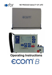
Operating Instructions
rbr-Computertechnik GmbH, Am Großen Teich 2, 58640 Iserlohn
Contents
Page
1. Introduction
3
2. Equipment
4
3. Flue gas measurement
3.1. Flue gas analysis
3.2. Draft measurement
3.3. Soot measurement
3.4. CO measurement (flue gas check)
3.5. Storing and printing results
3.6. NOx measurement (NOx standard)
6
9
10
11
12
14
4. Data processing
4.1. Data base / RAM
4.2. Working with chip cards
18
23
5. Instrument settings
26
6. Servicing
27
7. Technical data
30
8. Software instructions
35
Page 2
ecom-JN
1. Introduction
The ecom-JN is a combination measurement instrument for analysing
flue gases and other combustion process parameters. The flue gas
analysis is carried out using electrochemical fuel cells. Flue gas
temperature, input air temperature, differential pressure, soot number
and any values calculated from these values such as flue gas losses,
efficiency and the excess air complete the list of results available and
form the necessary parameters for the classification of small heating
installation according to the 1st BImSchV.
The rbr-ecom JN is the result of the many years of experience which
many users have had with the ecom-J and J-Plus series and combines
the highest possible safety requirements with user friendly operation
and technology using the best, most modern circuitry in a future
oriented design.
The following instructions describe the simple operation of the
instrument in the first, shorter section. This section should be read to
avoid mistakes and problems when using the instrument. The servicing
and maintenance information and the information on possible errors
should also be read. The second, somewhat longer section describes
the function of the processes used in the instrument and contains
details on technical data.
The instruction manual is set out to cover all possible options and so
includes the NOx and data processing modules.
Finally we would like to wish you every success in using the ecom-JN
in your every day work.
ecom-JN
Page 3
2. Equipment
Probes
Pistol grip probe (Standard):
- suitable for combined gas, flue gas losses,
draftt measurement and soot measurement
- Depth 290 mm
- Diameter = 10 mm
- Coaxial form with NiCr/Ni
thermoelement (T-Gasmax. = 500°C)
- Triple chamber tubing (3 m long)
- Heated soot measurement point
- Positioning cone
Multi hole probe (Option):
- CO measurement of gas burners
- 3 meter tubing
Heated sampling system (Option):
- Heated tubing (100 °C; 3.5 m long)
- Heated probe (100 °C) with 300 mm probe tubing
and integrated NiCr/Ni thermoelement (T-Gasmax. = 200°C)
- Hot gas filter
Sensors
T-room sensor (Standard):
- Room temperature sensor with positioning
magnet (T-roommax. = 99°C)
Page 4
ecom-JN
Standard fittings
- Soot number comparison scale
- Replacement filter
- Case carrying strap
- Operating instructions
- Data sheet
Optional extras
- RAM cards (standard 512 kB)
- Additional keyboard
- Matrix printer instead of thermal printer
- Peltier cooler instead of condensation trap
- Probe holder (movable)
- Undercase
- Extended sensor on request
Keyboard functions
Contrast
control
Zoom
<ZOOM>
Display
light
Draft meas.
<DRAFT>
CO-sensor
on/off
ecom-JN
Set menu
Cursor
<SET>
up
BImSchV
Leave
Paper line
CO-meas.
menu
feed
<MODE>
<ESC>
Print
<PRINT>
Control
Cursor
menu
down
<CTRL>
Soot meas.
Memory
<SOOT>
<m>
Enter
<E>
Page 5
3. Flue gas measurement
3.1. Flue gas analysis
After selecting the appropriate probe for the measurement, this should
be attached to the measurement point and the temperature sensor for
the input air should be positioned. Care should be taken to ensure that
all tubing and connections between the probe and the instrument are
correct. If a mains supply (230 V/50 Hz) is available nearby (mains
cable is 5m long) it should be used. The instrument can be powered by
the rechargeable batteries (when using a heated sampling system
mains supply must be used). If needed a tube should be connected to
the air input and an external air supply. A container for condensate
should be placed near the condensation pump outlet which is on the
lower right hand side of the instrument case.
Switch on the instrument.
Gas analysis
Data bank/RAM
Service card
select, <E> confirm!
Depending on the instrument either a menu appears on the display or,
if there is no data processing software present, the 3 minute calibration phase starts immediately.
To carry out a flue gas analysis, elect Flue gas measurement with the
cursor and confirm by pressing <E>. The last selected fuel type will
now appear in the display. The fuel type can be selected using the
arrow keys to change the display to the fuel required and is selected
by pressing <E>.
select, <E> confirm!
Calibration phase 2:59 min
Fuel type
CO2max
Natural gas
Natural gas
Town gas
Coke gas
Liquid gas
Oil
11.8
11.7
10.2
14.0
15.4
CO2max = 11,8 , A1 = 0,37 , B = 0,009
Page 6
ecom-JN
If the data processing package has been installed the user is asked if
the data base function is to be used. If "YES" is selected the data field
type can be selected. This is explained in chapter "Data processing".
Once the 3 minute calibration phase is completed the instrument is
ready for measuring. The gas path inside the instrument is switched
from fresh air to GAS and after a pause of approx. 20 seconds (the
time for gas to reach the sensor) the complete measurement display
appears. The display can differ depending on the sensors included in
the instrument.
rbr-ecom JN
O2
17,5
CO2
10,1
CO
145
NO
38
Eta
92,3
Losses 7,3
10.09.94
%
%
ppm
ppm
%
%
Exc.air
T.gas
T.air
Draft
Dew p.
12:34
1,15
140
24
-0,05
49
°C
°C
hPa
°C
+
Instruments with the NOx module have a separate display for NO, NO2
and NOx.
The <ZOOM> key can double the display size, i.e. after pressing once
the display changes from 8 lines to 4 lines.
O2
CO2
CO
Losses
17,5
10,1
145
7,3
%
%
ppm
%
The arrow keys can be used to alter the last two lines in the enlarged
display (in this case CO and Losses). The upper lines can be changed
by pressing the <ZOOM> key again, switching to a two line display.
O2
CO2
17,5 %
10,1 %
The last setting chosen remains so that the important values can be
set in the display.
ecom-JN
Page 7
Please note:
1.) The measurement must be carried out in the main gas stream. The
main gas stream is where T gas is at a maximum which can easily be
found using the trend display. As long as a "+" sign is visible in the
display the temperature being measured is rising, i.e. the probe is
moving towards the centre of the main gas stream. A - sign means that
the probe is being moved away from the main stream and the
temperature is dropping. The display is deleted if no change occurs for
3 seconds or more.
2.) Correct measurements appear in the display after a short delay
due to the time taken for the gas to reach the sensors and the time
taken for the electrochemical sensors to reach a stable signal. This
takes between 1 and 1.5 minutes. Measurements should not be saved,
noted or accepted until the value has stabilised. If the values still vary
by more than 2 ppm this could be due to an unstable draft behaviour in
the flue gas which gives rise to a variable main gas stream. This can
be confirmed by checking the draft value in the display. If this value
varies strongly or is considerably bigger than 0.20 hPa this can effect
the measurement.
3.) The values for CO2, Eta, Losses, Exc.air and Dew point are
calculated. They can only be calculated correctly when realistic values
for O2 and temperature are available. Care must be taken to ensure
that:
O2 < 20.5%
T gas - T air > +5°C
and
The dewpoint can only be calculated accurately if the current barometric
pressure was entered under <SET>.
Once the measurements are stable and reliable press <m> to store
the values in the memory. They can be stored here for printing out at a
later stage.
Page 8
ecom-JN
3.2. Draft measurement
The draft present in the flue gas channel has already been indicated
by the trend display earlier. The chimney draft value is not stored by
pressing <m> as the differential pressure sensor is very sensitive and
drifts. For this reason it is recommended that the sensor be re-calibrated
immediately before a measurement to ensure a good accuracy.
A differential pressure measurement is started by pressing <DRAFT>.
The current value is displayed as well as a reminder to reset the sensor
zero. To do this, remove the draft tubing and press the <MODE> key.
The sensor will now be re-calibrated.
Draft measurement
Draft - 0,05hPa
Reset zero point : release draft
hose, then press <MODE> !
Replace the tubing. The display now shows the exact value which can
saved value
:
-0.08 hPa
now be stored by pressing <m> which adds this value to those already
stored. The value saved is displayed. To leave the draft measurement
press <ESC>.
ecom-JN
Page 9
3.3. Soot measurement
A soot measurement is started by pressing <SOOT>. A soot measurement on an oil fired system consists of three suction phases in which a
volume of 1.63 (+/- 0.07) litres is drawn in. The colour (greyness) of the
soot filter disk is graded according to the 10 level Bacharach scale.
S o o t
smoke no.1
m e a s u r e m e n t
smoke no.2
_ . _ _ . _
oil trace: ___
smoke no. 3
_ . _
Mean value:
All three individual measurements are recorded. We recommend that
the soot measurements are heated to avoid the filter paper becoming
wet from the condensation which will effect the colour of the soot
deposited. The filter paper assembly in the probe is heated to 70°C.
Electric soot measurement with the ecom-JN
Switch on the heating for the sampling probe by pressing <SET> and
moving the cursor to “Probe heating NO” and pressing <E> to change
it to "YES". <ESC> leaves the menu.
Place a filter disk into the holder in the probe and press <E> to start the
measurement. The volume drawn is displayed and once 1.63 litres
has been reached the greyness value must be entered. To do this
remove the filter paper from the holder and compare it with the colours
on the scale. If a greater accuracy is required a densitometer (reflection photometer) can be used which gives a value accurate to one
decimal place. Enter the result and confirm with <E>. The cursor now
moves to the second soot measurement. Repeat this procedure until
all three soot measurements have been completed.
The cursor has now moved to the oil derivative display. <E> switches
between “YES”, “NO” and “—”. The average is calculated and
automatically stored. Pressing the <ESC> key ends the soot
measurement. Press <SET> to switch the probe heating off as the
previous settings are stored and would cause unnecessary drain on
the power supply when using the batteries.
Page 10
ecom-JN
Manual soot measurement and entering the values
If the soot measurement is carried out manually using a hand held
soot pump to reduce the load on the sensors, the results can be placed
in the instruments memory. The soot measurements are added to the
printer report and to the data for the measurement. Press <SOOT>
and then <MODE>. Type in the smoke number (decimal point using
the arrow key) and confirm with <E>. Repeat twice more and then
continue as described above. The values are stored automatically.
3.4. CO measurement (flue gas check)
When testing the safety of a gas fired incinerator a flue gas path test,
often called a CO measurement is carried out. The CO content of the
flue gas is measured after the flow restriction and the undiluted value
(0% oxygen remaining in the flue gas) is calculated. The flow of flue
gas after the flow restriction is no longer homogenous due to secondary
air flow and so the main stream measurement will contain errors. The
analysis of the gas therefore is carried out using a multi-hole probe
(optional extra). Align the holes of the multi-hole probe against the flow
direction in the gas stream.
Press the <MODE> key and the 4 values required for a CO measurement are shown in the display. The value shown after CO(U) is the
calculated CO content assuming the oxygen content is 0%, the undiluted CO concentration in the flue gas.
O2
CO (U)
CO
Exc. air
17,5 %
738 ppm
123 ppm
1,03
Once the display is stable press the <m> key to store the value. Press
<MODE> to return to the standard flue gas measurement mode.
ecom-JN
Page 11
3.5. Storing and printing results
The rbr-ecom JN has a 58 mm thermal printer for printing reports
(optional matrix printer). The printed report can be used as a copy of
the work carried out for the customer or as an archive copy of the
measurements.
A report is printed by pressing <PRINT> and contains only those values
stored in the memory at that time. A described earlier the individual
measurements are stored by pressing <m> (the soot measurement is
stored automatically). Once <PRINT> has been pressed the stored
values can be checked.
The report is printed by selecting “Start print”., and is structured as
follows :
Customers name and address form the data
ecom-JN
base (only appears if the relevant options
have been selected or installed)
name 1
name 2
text (2 lines each 20 characters long)
line 1
comments, notes, information...
date and time of report
result from flue check
flue gas analysis results according
to BImSchV
NO, NO2, NOx only shown if option installed
Differential pressure measurement
soot measurement results
8 lines of text each max. 20 characters in
length which can be programmed according
to the customers requirements either before
delivery or at a servicing (e.g. firm address)
Page 12
line 2
Date
Time
12.09.94
12:34:56
CO-measurement
O2
17,5 %
CO (U)
738 ppm
CO
123 ppm
Lambd.
1,15
BImSchV
Fuel type
Heating oil
T air
22 °C
T gas
140 °C
O2
13,2 %
CO
85 ppm
NO
43 ppm
NO2
5 ppm
NOx
48 ppm
Draft
-0,05 hPa
Smoke no. 1,2 1,3 1,4
Oil derivative
No
max. 8 lines of 20
characters
(name, adress, telephon,
text,...)
ecom-JN
Text input lines 1 and 2
In certain cases it can be useful to include additional comments in the
report (notes, comments, observations, etc.). This can be achieved by
selecting “Text input” with the cursor and pressing <E> :
Insert text
•
•
Cancel with <ESC> ! delete with <F2> !
Two lines each 20 characters in length are available for inputting any
information required. An external keyboard is available as part of the
data processing package, without this keyboard only numeric data can
be entered using the internal keyboard.
Whilst the report is being collated and printed all other functions are
inoperative.
Note:
The memory contents can be deleted by pressing <m> in the
appropriate mode (BImSchV measurement, CO measurement or draft
measurement). The "m" in the display disappears and the values in
the memory are deleted without being over written with by any current
results. To store the current values , the <m> key must be pressed
again and the "m" appears in the top right hand corner of the display
again.
ecom-JN
Page 13
3.6. NOx measurement (NOx standard)
The ecom-JN can be equipped with a complete NOx module which
comprises:
- NO sensor
- NO2 sensor
- peltier cooled gas heat exchanger
- heated sampling system (3.5 m long)
The instrument can also be equipped with only one sensor for
measuring the NO concentration although no NOx calculation can be
made in this case.
NOx is made up of the sum of the NO and NO2 concentrations in the
flue gas which depend on the fuel and the combustion process. Legal
limits and recommendation always refer to the sum of nitrogen oxides
(NOx).
Under normal conditions NO2 is very reactive and will be washed out
by condensation to form nitric acid (HNO3). For this reason the gas
path from the measurement point to the instrument must be kept
condensation free to avoid washing out off NO2.
The heated sampling system heats the head of the probe and the tubing
to a temperature (standard 100°C) above the water condensation point
(this is normally between 45 and 60°C) and so prevents condensation
forming. The peltier cooled gas heat exchanger shock cools the gas
down to a temperature of between 5 and 8°C. This causes excess
water and water vapour which can no longer be kept in the gas at this
temperature to condense out. The condensation is collected in a
container underneath the cooler and can be removed by pumping out
either as required or automatically when the instrument is switched off.
Page 14
ecom-JN
The gas is in the tubing for such as short time and is unable to react or
cool down any further on its way to the sensors so no further
condensation occurs.
The nitrogen oxides are measured separately using two sensors. Both
values are displayed and dealt with separately. Their sum is calculated
according to the conditions set :
NOx in ppm
NOx (ppm) = NO (ppm) + NO2 (ppm)
NOx in mg/m3
NOx (mg/m3) = (NO (ppm) + NO2 (ppm)) * 2.056
NOx in mg/kWh
Calculated from tables according to TA-Luft and
the fuel type.
The conversion factors for the individual gases are in the appendices.
Please note the following when measuring nitrogen oxides:
1.) Use the heated sampling system. Measurement carried out using
the normal sampling system without the gas cooler can have an error
due to up to 40% of the NO2 concentration being washed out.
2.) The heated sampling system can only be used with a mains power
supply. The power consumption is approx. 400 W.
3.) The set temperature is reached after approx. 5 minutes and is then
controlled by the programme.
4.) Be sure to connect the condensation tubing when using the heated
sampling system and gas cooler to avoid problems due to condensation
being pumped off.
ecom-JN
Page 15
4. Data processing
The ecom-JN data processing package consists of :
- RAM card slot
- Extended software
- External keyboard
- Centronics parallel port
- Optional: RAM cards in different sizes (standard 512 kB)
The extended software enables additional functions for storing and
administrating measurement results as well as long term measurements
with data logging.
Data processing with the no consists of two different methods:
1.) Processing of individual measurements and installation data. This
data can be stored on an external data carrier for processing at a later
stage. The data is stored in a standard format compatible with PC data
formats and existing software (e.g. regional administration programmes,
data bases).
2). Processing of long term measurement data with automatic recording
(data logger). The instrument records all measurement data over a
time period at programmable intervals or sends them via the serial and
parallel ports to a PC or printer. The preferred data carrier is again the
RAM card (if a PC is connected the data can be written directly to the
hard disk).
The data processing functions (other than those connected with
recording measurement data) can be used when the instrument is not
measuring. The pump and the sensors remain switched off and no
calibration is carried out when the instrument is switched on.
Page 16
ecom-JN
4.1 Data base / RAM
The JN uses RAM cards as storage medium for large amounts of data.
RAM cards with capacities up to 4 MB (4096 kB) can be used. As with
floppy disks in a PC, a RAM card must be formatted before it can be
used. The formatting procedure deletes all of the data previously stored
on the card and is irreversible. Approx. 1 kB is reserved on the card for
system information.
RAM cards are formatted by choosing the option “RAM card” from
the menu.
Select
Visualize/Print
Communication
RAM card
A list of further options appears along with information on the RAM
card.
Format
Cancel files
Configurate
Capacity
Reserved
512 kB
250 kB
General Data 0
Free
261 kB
Select “Format” and after the warning message has been confirmed
the RAM card is formatted. Once the formatting is finished the main
menu reappears.
Note : The standard setting for RAM cards is 512 kB, if RAM cards of
different capacity are used this must be set under “Configurate” as
otherwise the card will be incorrectly formatted.
The RAM cards can be used for storage and for data base functions.
With the data base function, data is loaded from a PC (e.g. installation
data, customer data) and the measurements are added later in situ.
Once the measurements are completed the data can be relayed to the
PC in the correct form and under the correct area. To do this an area of
the RAM card must be reserved.
ecom-JN
Page 17
The rest of the card can be used for other measurement data which
does not need to be stored under a specific installation, e.g. when
using the data logger function. Select “Configurate” from the menu.
Two lines appear in the display:
- Total
512 kB
- Reserved 256 kB
“Total” determines the total capacity of the RAM card. If this is different
from 512 kB press <E> to set the correct capacity. The values shown
are those for acceptable RAM cards. The reserved area is set similarly
by moving the cursor to “Reserved” and pressing <E> until the desired
value is reached. The reserved value is increased in steps of 64 kB.
Once the settings are correct press <ESC> to leave this menu.
“Cancel files” does not need much explaining. After the warning has
been answered with “YES”, all files on the card are deleted.
Warning: Due to the read / write mechanism used with RAM cards
accidentally deleted files cannot be recovered. The delete and format
functions should therefore only be used after the data on the card has
been copied onto a PC.
Communication
Once the RAM card has be prepared it can be used. The option
“Communication” accesses the functions load data base, send data
base and general data transfer. The options are selected with the cursor
and <E>.
Load data bank
Data is transferred from the PC via the RS 232 port from a particular
programme (e.g. the regional administration software). To do this the
RS 232 port on the ecom-JN is connected to the serial port on the PC.
C o m m u n i c a t i o n
Load data bank
Send data bank
Send general data
Page 18
ecom-JN
Data is transmitted according to the instructions given in the programme
on the PC. The data transfer must also be confirmed on the JN before
transferring. The reserved area on the card is formatted differently in a
few seconds (progress is shown on the display). The JN is then ready
to accept data from the PC.
The functions “Select” and “View / Print” are now available.
The “office work” with the JN is now finished and the JN can now be
used for actual measurements. The decisions whether to use a data
base and which storage medium to use are made after switching on
the instrument. The settings for storing general data on RAM cards are
found under "Set menu" (<SET>, function “times” and “data logger
: YES”).
Send data bank
Connect the JN and the PC via their RS 232 ports and start the
programme and follow the instructions. Chose the function “Send data
bank” on the JN and press <E>.
C o m m u n i c a t i o n
Load data bank
Send data bank
Send general data
The data will be sent to the PC. The data base on the RAM card contains
information on changes made which means that only data corresponding to actual measurements are transferred.
If there is general data in the reserved area on the RAM card which is
to be transferred to the PC (e.g. measurements from the data logger)
the RAM card data programme should be used. Connect the PC and
JN via the RS 232 port. Start the programme on the PC. Set the required
options on the PC and press ENTER. On the JN select the function
“Send general data” and press <E>.
ecom-JN
Page 19
Select and View / Print
The functions “Select” and “View / Print” can be used for checking the
measurement results and printing them out. Select the data to be viewed
by entering a search pattern (e.g. the name of a distributor) or a
customer number or memory number. If no data can be found, check
the search pattern to see if it is correct. The complete data base is
searched and data retrieved when at least 4 characters are in
agreement with the search string. Once the search is completed the
data is displayed and can be confirmed or re-selected.
“View / Print” can be used to view the entire contents of the memory
and print them out.
4.2. Working with chip cards
Only for instruments with chip-card-slot!
The rbr-ecom JN can read from and write to 512 byte chip cards. These
data carriers which look like telephone cards, can store approx. 500
characters of information. A chip card can be used as a installation
data card, a measurement file or as a job card.
Service card data
Meas. values
Record -> MC
Report
The cards memory is divided into two areas :
- standard data
- measurements
Page 20
ecom-JN
Standard data
Standard data are data describing an installation :
- Owner (max. 60 characters)
- Customer number (max. 20 characters)
- Burner manufacturer (max. 20 characters)
- Burner type (max. 20 characters)
- Year of manufacture (max. 10 characters)
- Fuel type (max. 20 characters)
- Hu (kWh/m3) (max. 6 characters)
- Jet size (max. 9 characters)
- Jet pressure (max. 6 characters)
- Boiler manufacturer (max. 20 characters)
- Boiler type (max. Characters)
- Year of manufacture (max. Characters)
- Nominal performance (kW) (max. 11 characters)
- Set performance kW) (max. 6 characters)
This data is either on the card if it has been prepared previously or it
can be entered directly into the ecom-JN using the keyboard if the chip
card is to be prepared during servicing or installing. The standard data
required is fixed as is the length of the data areas.
If a chip card is put into the ecom-JN the data is read from the card into
the instruments RAM.
Measurements
The measurement results contain all of the information from a
measurement. If a chip card has been inserted into the ecom-JN and
the <m> key is pressed the results are transferred form the instruments
RAM to the chip card. Any data already on the chip card is over written.
ecom-JN
Page 21
Store > MC
If the chip card is used as an installation card it generally remains with
the heating installation with the data stored on it. The data can be
transferred to a RAM card and then to a data processing system for
general processing or report generation. This is done by selecting
“Store >MC” with the cursor (MC means memory card) and storing
the data on the un-reserved part of the RAM card (general data).
Report
In many cases it is necessary to store additional information along with
the measurement information already available. Up to now the data
processing and handling using the rbr-ecom JN has been done without
paper using the most modern techniques. It is therefore only natural
that any additional information be handled in the same way.
Select “Report” with the cursor, a blank display screen appears which
can accept up to 280 character from the external keyboard.
7 x 40 charakters
of text can be entered
Report
Delete <F2>!
There are no restraints on the text which can be entered and it is stored
as written in the instruments RAM. The function “Store >MC” transfers
the text along wit the chip cards contents to the RAM card.
Once the JN is switched off all of the data in its RAM are deleted, only
data stored on RAM cards or chip cards remains.
Page 22
ecom-JN
5. Instrument settings
The ecom-JN functions are described in the previous sections. The
calculated and measured values can be altered by changing certain
options via the settings on the JN. Pressing <SET> when in the flue
gas measurement mode accesses the options menu. Move the cursor
to the relevant position and press <E>.
E i n s t e l l u n g e n
Unit
ppm
Undiluted
Nein
Refe.-O2
0,0 %
Boiler temp.
Air pres. 1013 mbar
Probe heat.
No
Fuel
Clock set
Fuel ty. <- PC
Times
Data logger No
The following settings are possible :
Unit
- Factor for calculating gas concentration in:
- ppm = volume concentration (parts per million)
3
- mg/m = mass concentration per volume
- mg/kWh = mass concentration over output
Undiluted
- Calculation of gas concentration using reference
oxygen YES/NO Formula for calculation :
Erel = Emeas *
21 - O2rel
21 - O2meas
Reference O2
- input reference oxygen value O2rel
Boiler temp.
- input boiler temperature
Air pressure
- barometric air pressure used in the dew
point calculation (see appendix)
ecom-JN
Page 23
Probe heating
- soot probe heating on/off
Fuel
- change the fuel type (e.g. when measuring on combination systems)
Clock set
- set the internal clock
Fuel type <- PC
- changes the fuel type menu in the instruments EEPROM
by accessing PC data via the RS 232 port.
Times
- set the memory and output options for sending data to
RAM card and Centronics port
Data logger
- switch the data output and storing on or off
6. Servicing
To ensure interruption free use of the rbr-ecom JN please take note of
the following information for servicing and maintaining parts :
Filter
The JN is equipped with filters to protect the tubing and sensors and
these need to be checked regularly :
Fine dust filter on the gas cooler
Unscrew the lid of the gas cooler and
check the particle filter. It should be
changed when the filter is dark grey
to black in colour where the gas comes
in (smoke number approx. 2 - 3).
Page 24
Fine dust filter
ecom-JN
Filter in the heated probe (only applies to instruments with the
heated sampling system)
Important : Always remove the mains connection before opening the
probe (the heating requires 230 V)
Open the bayonet fitting on the probe and remove the filter if it is dark
grey in colour. The filter used is a 8 m boron silicate glass fibre mat.
SO2/NOx filter
In the tubing leading to the CO sensor on the rear of the instrument is
a chemical filter for filtering SO2 and NOx out of the flue gas. The filter
material is manganese-4-oxide granules and should be changed once
it has turned grey (colour change: pink>brown>black>grey>white).
Sensors
After switching on the sensors are calibrated with fresh air. The
instrument constantly checks the sensor status. New sensors age due
to the reagents being used up (oxygen sensor) or due to dirt or being
exposed to concentrations above their standard rang (toxic gas
sensors). The initial values for sensors in check mode are:
Oxygen sensor
toxic gas sensor
approx. 18,000 mV
0 mV (+/- 150)
These values are relative values created by the programming. The
check mode <CTRL> for the toxic gas sensors should show a value <
+/- 150 mV, if not the calibration should be repeated. If an error occurs
during calibration and does not disappear after repeating the calibration
several times the instrument should be sent in for servicing.
The oxygen sensor should read > 7000 mV. If this is not the case it
should be exchanged.
Probe and tubing
The tubing and the probe should be cleaned regularly, depending on
use, to remove dirt and to avoid wear due to corrosion taking place.
The coaxial probe can be dismantled by unscrewing the outer tube.
The inner tube is connected to the grip. The thermo-element is permanently attached to the grip. The tubing can be cleaned after removing it
from the connections on the instrument and probe (use warm water
and allow to dry or blow dry).
ecom-JN
Page 25
Power supply
A rechargeable battery is used for mains free operation. The battery
has a capacity of 3,4 Ah and the length of use depends on the operating
mode (approx. 1 hour with gas cooler and internal heating with heated
soot measurements). The battery is recharged by plugging the instrument into the mains (charge time approx. 10 hours). Switching on is
not necessary. The battery should be recharged once the voltage display
reads less than 11 V (the critical point is 10.5 V after this the instrument
will not function). The battery voltage is only displayed when the
instrument is not using the mains supply.
7. Technikal data
General data
Power supply
mains 220 - 240 V / 50 Hz
battery 12 V / 3,4 Ah (lead gel)
Battery operation
> 1 hour with full load
low charge protection 10.5 V
Charge time
approx. 8 - 10 hours
charging current
limit over charge protection
Power consumption
max. 100 W without heated
sampling system and gas cooler
approx. 400 W with heated
sampling system and gas cooler
Optional extras
- heated sampling system (Tmax. 100°C: length 3.5 m) with heated
probe and pre-filter (hot gas filter; T gas max. = 200°C)
- RAM card data carrier (Standard 512 kB; PCMCIA-norm)
- case for additional equipment
Dimensions
Case (W x L x H)
Weight
Page 26
:450mm x 300mm x 250mm
:approx. 12 kg with standard probe 300 mm
ecom-JN
Measured values
Parameter
Range
Principle
O2
CO
NO (Option)
NO2 (Option)
CO% (Option)
Draft
T-Gas
T-Air
0 ... 21 Vol.-%
0 ... 4.000 ppm
0 ... 2.000 ppm
0 ... 200 ppm
0 ... 10 Vol.-%
0 +/- 20 hPa
0 ... 500 °C
0 ... 99 °C
Electrochemistry
Electrochemistry
Electrochemistry
Electrochemistry
Electrochemistry
DMS-bridge
Thermocouple NiCr/Ni
Semi-conductor
Calculated values
Parameter
Range
CO2
0 - CO2max
CO2= CO2max*
0 - 99,9 %
qA =
Losses
Formula
(
A2
21 - O2
(
1-
O2gemessen
21
)
)
+ B * ( TAbgas - TLuft )
Efficiency
0 - 99,9 %
ETA = 100 - qA
Excess air
1-∞
λ = 1+
O2
21 - O2
Fuel types
Fuel
Fuel oil
Natural gas
Town gas
Coke gas
Liquid gas
ecom-JN
CO2max values and factors
A1
A2
B
0,50
0,37
0,35
0,29
0,42
0,68
0,66
0,63
0,60
0,63
0,007
0,009
0,011
0,011
0,008
CO2max
15,4
11,8
11,7
10,2
14,0
Page 27
Conversion factors (ppm - mg/m3 - mg/kWh)
Gas ppm to mg/m3
mg/m3 to ppm
fuel type
CO
NOx
SO2
O2
CO
NO
NO2
SO2
0,699
0,8
0,75
0,49
0,35
Nat. gas L
Nat. gas H
Propan
Town gas
Oil EL
Oil S
1,092
1,073
1,05
1,002
1,105
1,12
1,795
1,762
1,722
1,647
1,816
1,847
2,587
2,63
1,429
1,25
1,34
2,05
2,86
Dew point calculation
The dew point calculation uses the approximation given in DIN 4705 part 1.
χ H2 O =
Moisture content of the gas
fw is a fuel factor
100
+ 11
.
fW
1+
CO2
in %
gas = 57
town gas = 53
liquid gas = 77
oil = 111
PD =
χ H2 0
* Pair
in Pa
4077.9
− 236.67
23.6448 − ln PD
in °C
Partial pressure of steam calculation
100
Pair = atmospheric air pressure (900 ... 1100 mbar)
Dew point calculation
Page 28
TP =
ecom-JN
Gas cooler (schematic)
Gas
in
Gas
out
Peltier
element
Level
indikator
Condensation
removal
Ventilator
Gas at a temperature above the steam condensation point (35 - 65 °C)
passes through a long, surface treated metal spiral with good heat
conducting properties. The gas losses its heat to the metal. A direct
current driven peltier element (semi conductor cooling element) is
thermal connected to the metal spiral and to another spiral with
ventilation and cooling fins. The current flowing through the peltier
element causes a heat transfer from warm to cold thus removing the
warmth from the gas flowing through the spiral and transfers it to the
cooler. This warmth is then removed by the ventilator.
The condensation formed by the gas cooling is collected in a container
below the cooler and periodically pumped off using a peristaltic pump
(triggered by the operator or by the level indicator).
The gas suction pump prevents the gas from remaining too long in the
presence of condensation and so reduces any losses due to washing
out reactions.
The gas temperature on leaving the cooler is approx. 5 °C with a relative
humidity of approx. 100% (water vapour fraction < 7 g/kg).
ecom-JN
Page 29
Coaxial probe
6
1
7
2
1. Inner tube (gas)
2. Outer tube (draft)
inner Ø = 6 mm
outer Ø = 8 mm
inner Ø = 9 mm
outer Ø = 10 mm
8
3. Draft connection (3 ribs, same on instrument)
4. Gas connection (2 ribs, same on instrument)
5. Connection for T gas
6. Temperature sensor for T gas (NiCr/Ni, not visible)
7. Slot for soot filter with pressure piston
8. “Trigger” for the piston.
3
4
5
The probe can be dismantled for cleaning :
1. Unscrew the outer tube (draft) form the grip and remove it.
2. The inner tube (gas) can now also be removed (sealing o-ring).
When reassembling care must be taken to ensure that the thermal
wire tip does not touch the tube.
Page 30
ecom-JN
Subject to technical changes
12.2004
rbr Computertechnik GmbH
Am Großen Teich 2
D-58640 Iserlohn (Sümmern)
Telefon: +49 (0) 23 71 - 9 45-5
Telefax: +49 (0) 23 71 - 4 03 05
Internet: http://www.rbr.de
eMail: [email protected]
ecom-JN
Page 31


