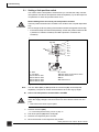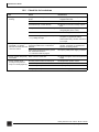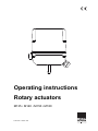
1
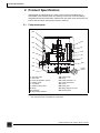
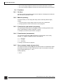
Operating instructions Rotary actuators M135 • M140 • M150 • M180 June 2012 / 118614 / EN General information General information Proof of amendment Copyright Subject to alterations Version Date Changes 1.0 June 1998 Initial preparation 2.0 June 2012 Complete revision and supplements The copyright for this operating manual as well as all rights in case of patent awarding or registration of registered design remain with the manufacturer! The regulations, directives, standards etc. are compliant with the current state of information at the time of development and are not subject to modification service. They must be applied by the operator at his own responsibility in their latest valid version. Concerning all data, information, and illustrations in this manual we reserve the right of technical modifications and improvements. No claims can be considered for alteration or rework of already delivered rotary actuators. Manufacturer HORA Business area Flow Control Holter Regelarmaturen GmbH & Co. KG Helleforthstrasse 58–60 33758 Schloss Holte-Stukenbrock Germany phone: +49 (0) 5207/8903-0 mail: [email protected] www.hora.de Rotary actuators 135 • M140 • M150 • M180 2 Version 2.0 - June 2012 Operating instructions Content Content 1 Safety ......................................................................... 4 1.1 Proper use ............................................................... 4 1.2 For the owner-operator ............................................ 4 1.3 Personnel................................................................. 5 1.4 Prior to work............................................................. 5 1.5 In operation.............................................................. 5 1.6 Work environment.................................................... 5 2 Product Specification ............................................... 6 2.1 Component parts ..................................................... 6 2.2 Accessories ............................................................. 7 2.3 Operating modes ..................................................... 7 2.3.1 Three-point mode ......................................... 7 2.4 Functions ................................................................. 8 2.4.1 Set time ........................................................ 8 2.4.2 Manual operating.......................................... 8 2.4.3 Potential-free path switch (accessory).......... 8 2.4.4 Potentiometer (accessories)......................... 8 2.4.5 Servo actuator heater (accessories)............. 8 2.5 Technical data ......................................................... 9 2.6 Type plate .............................................................. 10 3 Transportation & Storage ....................................... 10 4 Assembly..................................................................11 4.1 Checking the scope of delivery ..............................11 4.2 Preparing assembly ...............................................11 4.3 Mount rotary actuator on flap .................................12 4.4 Assembling/disassembling a hood.........................13 4.5 Electrical connection ..............................................14 4.6 Fitting accessories .................................................16 4.6.1 Fitting path switches WE 3 and WE 4.........16 4.6.2 Fitting a potentiometer ................................17 4.6.3 Fitting the actuator heater...........................18 5 Commissioning........................................................19 5.1 Setting a limit position switch .................................20 5.2 Setting the potential-free path switches .................21 5.3 Setting a potentiometer ..........................................22 5.4 Commissioning.......................................................23 6 Operation..................................................................24 6.1 Changing between manual and automatic mode...24 7 Maintenance, care and repairs ...............................24 8 Spare parts...............................................................25 9 Decommissioning and disposal.............................25 10 Removal of faults.....................................................25 10.1 How to remedy faults .............................................25 10.2 Check list for breakdown........................................26 Rotary actuators 135 • M140 • M150 • M180 Operating instructions Version 2.0 - June 2012 3 1 Safety 1 Safety Please carefully read this operating manual and in particular the following safety notes prior to installation and operation. DANGER WARNING CAUTION ATTENTION Hint: 1.1 DANGER Immediately threatening risk which will result in death or serious injuries of the body. WARNING Potentially dangerous situation which might result in death or serious injuries of the body. CAUTION Potentially dangerous situation which might result in minor injury of the body. Indicates a risk which may be result in property damage. ATTENTION Potentially dangerous situation where the product or an object may be damaged in its environment. Notes for application and other useful information. Proper use Rotary actuators M135, M140, M150, M180 are controlled by three-position controllers. The rotary actuators of the production series described herein are used to adjust flaps. In order to ensure application for the purpose intended compare the above type designation for compliance with the nameplate of the rotary actuators prior to starting any action. The specifications on the type plate are standard for the technical data of the rotary actuators as well as the requirements for the public power supply. Any use for purposes other than the intended as specified above, deviating tasks as well as operation at other than the admissible mains conditions shall be deemed application for purposes other than the intended. The owner shall be solely responsible for the risk to man and equipment as well as other assets when used for purposes other than the intended! The intended use also includes the compliance with accident preventions, DIN VDE regulations and safe working practices for all measures described in these operating instructions in due consideration of prevailing rules. 1.2 For the owner-operator Keep the operating manual always within reach at the place of operation of the rotary actuators! Comply with the relevant applicable labor safety, accident prevention and DIN VDE regulation for installation, operation and maintenance. Follow the additional regional, local or internal safety regulations, if any. Rotary actuators 135 • M140 • M150 • M180 4 Version 2.0 - June 2012 Operating instructions 1 Safety Make sure that any person entrusted to carry out one of the actions described in this operating manual has read and understood this manual. 1.3 Personnel Only qualified personnel shall work at or near these rotary actuators. Qualified persons are deemed persons who are familiar with the installation, erection, startup and operation and/or maintenance of the rotary actuators or have been qualified appropriately for their work. The necessary and prescribed qualifications include: • Training / instruction or authorization to turn on /off circuits and appliances / systems according to EN 60204 (DIN VDE 0100 / 0113) and the standards of safety technology. • Training or instruction according to the standards of the safety technology concerning care and use of adequate safety and work protection equipment. • First Aid training. Work safely and refrain from any mode of working which might in any way endanger the safety of persons or the rotary actuator and/or other assets. 1.4 Prior to work Prior to any work check whether the types indicated here are in compliance with the information of the nameplate at the rotary actuator: Rotary actuators M135, M140, M150, M180. 1.5 In operation Safe operation is possible only if transport, storage, installation, operation and maintenance are carried out properly and in accordance with safety standards. Transport, Installation and Assembly Servicing and maintenance 1.6 Follow the general setup and safety regulations for heating, air-conditioning and pipeline construction. Use the tools properly. Wear the required personal protective equipment and other protective equipment. Make sure that qualified personnel isolate the rotary actuator prior to maintenance or repair work according to DIN VDE. Work environment Note the information about the work environment as specified in the technical data. Rotary actuators 135 • M140 • M150 • M180 Operating instructions Version 2.0 - June 2012 5 2 Product Specification 2 Product Specification Geared down by helical gears, the rotary motion of the reversible motor is transmitted to the actuator shaft, thus serving to move the connected fittings. Integrated slow-down limit position switches turn the motor off as soon as the set point of the slow-down limit position switch is reached. 2.1 Component parts 200 200 M135, M140, M150, M180 103 103 361 361 102 102 83 83 40 40 108 108 101 101 83 83 34 34 37 37 16 16 480 480 482 482 1 X 230 1x230 2x231 2 X 231 15 15 15 16 34 37 40 83 101 102 103 Gear with shaft Gear case Rotary knob (MAN / AUTO) Holding angle Cam block Distance sleeve SW 7 Motor* Condenser* Stop position switches Fig. 1 * 108 200 230 231 361 480 481 482 Terminal strip Hood* Cable duct M20 x 1.5 Choke nipple M16 Screw Name plate Wiring diagram in hood Warning signs Component part denominations This component part is available as a spare part! Rotary actuators 135 • M140 • M150 • M180 6 Version 2.0 - June 2012 Operating instructions 2 Product Specification 2.2 Accessories 106 Potential-free path switches Fig. 2 Potential-free path switches 180 Potentiometer add-on kit Fig. 3 Potentiometer add-on kit 190 Actuator heater Fig. 4 2.3 Actuator heater Operating modes The rotary actuator can be operated manually or automatically. In manual mode the rotary motion is carried out with the help of the hand lever on the add-on kit. • In automatic mode the rotary motion is electrically controlled. 2.3.1 Three-point mode The direction of motion is set via the control voltage on terminal 2 and 3 on the terminal PCB: Rotary actuators 135 • M140 • M150 • M180 Operating instructions Version 2.0 - June 2012 7 2 Product Specification • If the control voltage is applied to terminal 2 the actuator shaft will turn clockwise. • If the control voltage is applied to terminal 3 the actuator shaft will move anti-clockwise. 2.4 2.4.1 Functions Set time The time in which the actuator shaft covers a distance of 90 degrees is called set time. Set time is specified in s/90°. 2.4.2 Manual operating In manual mode you can change the rotary motion manually without supply voltage. • In manual mode the supply voltage needs to be turned off by qualified staff. 6.1 Changing between manual and automatic mode on page 24 2.4.3 Potential-free path switch (accessory) The optional path switch allows you (106) to set two actuating positions within which a potential-free contact is opened or closed. 5.2 Setting the potential-free path switches on page 21 2.4.4 Potentiometer (accessories) The optional potentiometer (180) indicates the actual position of the rotary actuator. 0° Angles of rotation up to 90° are issued as: • 0 ... 200 Ohm • 0 ... 1 k Ohm • 0 ... 10 k Ohm 5.3 Setting a potentiometer on page 22 2.4.5 Servo actuator heater (accessories) The optional actuator heating (190) prevents the formation of condensation inside the actuator and ensures at the same time the ease of movement for the gear even at temperatures up to c. -20°C. Heating capacity: • 25 VA Rotary actuators 135 • M140 • M150 • M180 8 Version 2.0 - June 2012 Operating instructions 2 Product Specification 2.5 Technical data Type M135, M150 M140, M180 Supply voltage: 230 V AC + 6% -10% 24 V AC ± 10% 230 V AC + 6% -10% 24 V AC ± 10% Power consumption M135 = 9 VA M150 = 12 VA M140 = 55 VA Weight 2.5 kg 3 kg Dimensions See technical data sheets Frequency 50/60 Hz ±5% 50/60 Hz ±5% Ambient temperature 0 to +50°C 0 to +50°C Protection type IP 54 IP 54 Operation mode S1-100% ED M180 = 26 VA M140 = S3-50% ED M180 = S3-60% ED Torque / M135 = 35 Nm / 130 s/90° M140 = 50 Nm / 10 s/90° Set time at 50 Hz M135 = 15 Nm / 70 s/90° M180 = 80 Nm / 130 s/90° M150 = 50 Nm / 130 s/90° M180 = 80 Nm / 70 s/90° M150 = 40 Nm / 70 s/90° Input signal Y Three-point Limit stop cut-off Slow-down, infinitely variable max. 320° table 1 Three-point Technical data Rotary actuators 135 • M140 • M150 • M180 Operating instructions Version 2.0 - June 2012 9 3 Transportation & Storage 2.6 Type plate The type plate is attached to the housing of the rotary actuator. It bears the type denomination, serial number (s/no) and date of manufacture (last four digits). 2.1 Component parts on page 6 M135 F.-Nr.: 11207991/01/1211 AC 50 Hz 230 V 130 s / 90° IP 54 9 VA 35 Nm S1 100% ED Fig. 5 Example of type plate 3 Transportation & Storage Non-compliance with safety regulations may result in injury! • Wear the required personal and other safety equipment. CAUTION • Avoid impacts, blows, vibrations etc. to the rotary actuator. • Store the rotary actuator (and, where appropriate, the entire controlling device) in a dry place. • Keep to the specified transport and storage temperatures between -20 to +65°C. Rotary actuators 135 • M140 • M150 • M180 10 Version 2.0 - June 2012 Operating instructions 4 Assembly 4 Assembly Prior to installing a rotary actuator: 4.1 Checking the scope of delivery on page 11 4.2 Preparing assembly on page 11 The following sequence of operations is part of the rotary actuator assembly: 4.3 Mount rotary actuator on flap on page 12 4.4 Assembling/disassembling a hood on page 13 4.5 Electrical connection on page 14 4.1 Checking the scope of delivery 1 Check the packaging for damage. 2 Dispose of packaging in an environmentally friendly manner. 3 Check the delivered items against the delivery note in order to see whether the delivery is complete. 4 Report any missing or damaged products to the manufacturer. 4.2 Preparing assembly 1 Allow for about 160 mm space above the hood at the site of installation. 2 Check the working environment before assembling and commissioning the rotary actuator. 3 Ensure that the flap is installed correctly. For details please refer to the installation instruction for the flap. 4 Do not arrange rotary actuators in a suspending arrangement. M M M M Fig. 6 Assembly position Rotary actuators 135 • M140 • M150 • M180 Operating instructions Version 2.0 - June 2012 11 4 Assembly 4.3 Mount rotary actuator on flap If rotary actuator and flap are supplied as separate deliveries you will have to mount the rotary actuator on the flap. 11 55 55 306 306 426 426 448 448 308 308 428 428 351 351 66 1 6 55 306 308 Knee-Bracket Coupling Manual lever Thrust washers Thrust washers Fig. 7 351 426 428 448 Spiral clamping pin Hexagon screws Hexagon screws Hexagon nuts Add-on kit for flaps How to assemble a rotary actuator 1 Secure the coupling (6) to the actuator shaft with pins using the spiral pin (351) 2 Attach the knee (1) below the actuator with the four hexagon screws (426), using spanner width 10 and thrust washers (306) applying a torque of 5 Nm. 3 Turn the hand lever (55) into the coupling (6). 4 Put the actuator with add-on kit on the flap. 5 Insert the four hexagon nuts (448) in the slots of the knee (1). 6 Insert the hexagon screws (428) spanner width 13 and slipped on thrust washers (308) from below through the flap flange. 7 Connect the four hexagon screws (428) spanner width 13 to the hexagon nuts (448) applying a torque of 7 Nm. How to disassemble a rotary actuator 1 Follow the sequence of operation in reverse order. Rotary actuators 135 • M140 • M150 • M180 12 Version 2.0 - June 2012 Operating instructions 4 Assembly 4.4 Assembling/disassembling a hood The terminals for electric connection are positioned under the hood. Risk of injury from electric shock by live parts! When the power supply is on there is a danger of electric shock due to live parts. • Prior to commencing any work, ensure that the actuator is safely disconnected from the power supply system. WARNING • Secure against unauthorised restarting. • Remove the hood only temporarily. Remove the hood 1 Detach the screws.(361) 2 Carefully remove the hood (200) . 361 361 361 361.1 200 200 200 Hood Fig. 8 361 Screws Remove the hood How to put the hood back on 1 Put the hood (200) back on. 2 Check the hood for correct fit to ensure air-tightness for the actuator housing. 3 Secure the hood with screws (361). Rotary actuators 135 • M140 • M150 • M180 Operating instructions Version 2.0 - June 2012 13 4 Assembly 4.5 Electrical connection Danger of life caused by incompetent staff! Electrical connections carried out by unqualified staff may result in death, severe bodily injury or considerable material damage. WARNING • Make sure that such all work is carried out by qualified staff. 1.3 Personnel on page 5 Risk of injury from electric shock by live parts! When the supply voltage is turned on there is a risk of electric shock from live parts. WARNING • Prior to commencing any work, ensure that the actuator is safely disconnected from the power supply system. • Secure against unauthorised restarting. How to prepare the electric connection 1 Ensure that the supply voltage matches the specifications on the type plate of the rotary actuator. 2 To avoid breakdown, construct the line diameter according to actuating performance and required line length. 3 Check the supply voltage. If the required tolerance is not achieved by a power transformer you will have to use an AC voltage stabilizer. 2.5 Technical data on page 9 How to establish electrical connection 1 Remove the hood (200). Remove the hood on page 13 2 Guide the cable through the cable duct in the transmission case to the terminal strip. 3 Connect the power supply according to the wiring diagram. Fig. 9 Wiring diagram on page 15 Hint: 4 The wiring diagram (481) is positioned on the inside of the hood (200). Tighten the screw joint. Malfunction due to parallel circuit • The connection of several actuators via one output contact is prohibited! ATTENTION • One coupling relay per actuator must be provided if several actuators are to be run on a parallel circuit! Rotary actuators 135 • M140 • M150 • M180 14 Version 2.0 - June 2012 Operating instructions 4 Assembly C C WE 1 WE 2 WE 3 WE 4 N1 2 3 20 21 22 23 24 25 P1 P2 30 31 32 33 34 35 H 40 41 L N PE Fig. 9 Wiring diagram Terminal Description PE / Protective conductor N1 Supply voltage: 2 Control voltage for rotary motion anti-clockwise 3 Control voltage for rotary motion clockwise 20, 21, 22 Terminals path switch unit WE 3 23, 24, 25 Terminals path switch unit WE 4 30, 31, 32 Terminals potentiometer P1 33, 34, 35 Terminals second potentiometer P2 40, 41 Terminals actuator heater table 2 Key to wiring diagram Rotary actuators 135 • M140 • M150 • M180 Operating instructions Version 2.0 - June 2012 15 4 Assembly 4.6 Fitting accessories Accessories are not part of the scope of delivery for the rotary actuator unless expressly ordered! The rotary actuators are prepared for retro-fitting with: • Path switch (106) • Potentiometer (180) • Actuator heater (190) 2.2 Accessories on page 7 4.6.1 Fitting path switches WE 3 and WE 4 Risk of injury from electric shock by live parts! When the supply voltage is turned on there is a risk of electric shock from live parts. WARNING • Prior to commencing any work, ensure that the actuator is safely disconnected from the power supply system. • Secure against unauthorised restarting. 1 1 Remove the hood (200). 4.4 Assembling/disassembling a hood on page 13 2 Remove slotted screw M3 x 25 (393) and thrust washer. 3 Put path switches WE 3 (45.3) and WE 4 (45.4) on pin (350). 4 Secure path switches WE 3 (45.3) and WE 4 (45.4) with slotted screw M3 x 45 (393) and thrust washer. 5 Run the cables for the path switches to the angle bracket. 6 Secure the terminals for the pacam diskth switches with the slotted screws on the angle bracket at terminal designations 20, 21, 22 and 23, 24, 25. Fig. 9 Wiring diagram on page 15 7 Set the path switches. 5.2 Setting the potential-free path switches on page 21 64 12 45.4 45.3 40 45.2 45.1 170 350 393 106 WE 4 WE 3 WE 2 WE 1 12 Shaft 40 Cam block 45.1 Cam disk for WE 1 45.2 Cam disk for WE 2 45.3 Cam disk for WE 3 45.4 Cam disk for WE 4 Fig. 10 64 106 170 350 393 Pointer Path switch / limit position switch Path switch board Pin Slotted screw Fit path switch Rotary actuators 135 • M140 • M150 • M180 16 Version 2.0 - June 2012 Operating instructions 4 Assembly 4.6.2 Fitting a potentiometer Risk of injury from electric shock by live parts! When the supply voltage is turned on there is a risk of electric shock from live parts. WARNING • Prior to commencing any work, ensure that the actuator is safely disconnected from the power supply system. • Secure against unauthorised restarting. 1 Remove the hood (200). 4.4 Assembling/disassembling a hood on page 13 2 Hint: Attach the potentiometer board (180) with slits in the recess of the hexagon sleeves underneath the path switch using slotted screw (394) M4 x 20 and thrust washers. Ensure correct meshing of gears. 3 Run the cable for the potentiometer to the angle bracket. 4 Secure the terminals of the path switch with the slotted screws on the angle bracket at terminal designations 30, 31, 32. Fig. 9 Wiring diagram on page 15 5 Set the potentiometer. 6 5.3 Setting a potentiometer on page 22 180 180 105 105 105 P1 394 105 Potentiometer 180 Potentiometer board Fig. 11 394 Slotted screw Fitting a potentiometer Rotary actuators 135 • M140 • M150 • M180 Operating instructions Version 2.0 - June 2012 17 4 Assembly 4.6.3 Fitting the actuator heater Risk of injury from electric shock by live parts! When the supply voltage is turned on there is a risk of electric shock from live parts. WARNING • Prior to commencing any work, ensure that the actuator is safely disconnected from the power supply system. • Secure against unauthorised restarting. 1 Remove the hood (200). 4.4 Assembling/disassembling a hood on page 13 2 Remove the slotted screw and screw down the distance sleeve. 3 Secure the actuator heater (190) on the distance sleeves with slotted screws M4 x 8 and thrust washers. 4 Run the cable for the actuator heater to the angle bracket. 5 Secure the terminals for the actuator heater with slotted screws on the angle bracket at terminal designations 40, 41. Fig. 9 Wiring diagram on page 15 190 Fig. 12 Fitting the actuator heater Rotary actuators 135 • M140 • M150 • M180 18 Version 2.0 - June 2012 Operating instructions 5 Commissioning 5 Commissioning Risk of injury from electric shock by live parts! When the power supply is on there is a danger of electric shock due to live parts. • Prior to commencing any work, ensure that the actuator is safely disconnected from the power supply system. WARNING • Secure against unauthorised restarting. ATTENTION Risk of damage to device when adjusted manually The actuator may sustain damage if the rotary actuator is not disconnected from the power supply. • Disconnect actuator from power supply. 1 Ensure that the hood (200) is mounted. 2 Turn the rotary knob to (34) AUTO position. 3 Make sure that the motor is turned off in the end positions (limit position switch). 5.1 Setting a limit position switch on page 20 Rotary actuators 135 • M140 • M150 • M180 Operating instructions Version 2.0 - June 2012 19 5 Commissioning 5.1 Setting a limit position switch You need to set the limit position switch before you can take the rotary actuator into operation. Set the two limit position switches separately. Try out the sequence of operations for each limit position switch once. ATTENTION Risk of damage from incorrectly set limit position switches The limit position switches WE 1 and WE 2 turn off the motor in a path-dependant way. Do not change the factory setting if the actuator is delivered together with the flap. • If actuator and flap are delivered separately, set the limit position switches WE 1 (direction of rotation clockwise) and WE 2 (direction of rotation anticlockwise). 64 12 45.4 350 393 106 WE 4 WE 3 WE 2 WE 1 12 Shaft 40 Cam block 45.1 Cam disk for WE 1 45.2 Cam disk for WE 2 45.3 Cam disk for WE 3 45.4 Cam disk for WE 4 Fig. 13 Hint: 45.3 40 45.2 45.1 170 64 106 170 350 393 Pointer Path switch / limit position switch Path switch board Pin Slotted screw Setting limit position switch The cam disks (45.1) to (45.4) inside the cam block (40) can be adjusted separately. The pairs of screws are allocated to each cam ring by height. How to set limit position switches WE 1 and WE 2 Risk of injury from electric shock by live parts! When the supply voltage is turned on there is a risk of electric shock from live parts. WARNING • Take care not to touch any live parts. 1 Remove the hood (200). 4.4 Assembling/disassembling a hood on page 13 2 Pull off the pointer (64) off the shaft (12). 3 Remove the respective pair of screws. 4 Move the actuator in the respective end position. Rotary actuators 135 • M140 • M150 • M180 20 Version 2.0 - June 2012 Operating instructions 5 Commissioning 5 Turn off the motor. 6 Turn the cam disk until the path switch switches. 7 Tighten the respective pair of screws. 8 Slip the pointer (64) on the shaft (12). Ensure that the pointer‘s locking pin engages with the designated drilled hole in the shaft. 5.2 Setting the potential-free path switches Set the two path switches separately. Try out the sequence of operations for each path switch once. 64 12 45.4 45.3 40 45.2 45.1 170 350 393 106 WE 4 WE 3 WE 2 WE 1 12 Shaft 40 Cam block 45.1Cam disk for WE 1 45.2Cam disk for WE 2 45.3Cam disk for WE 3 45.4Cam disk for WE 4 Fig. 14 Hint: 64 106 170 350 393 Pointer Path switch / limit position switch Path switch board Pin Slotted screw Setting path switches The cam disks (45.1) to (45.4) inside the cam block (40) can be adjusted separately. The pairs of screws are allocated to each cam ring by height. How to set potential-free path switches Risk of injury from electric shock by live parts! When the supply voltage is turned on there is a risk of electric shock from live parts. WARNING • Take care not to touch any live parts. 1 Remove the hood (200). 4.4 Assembling/disassembling a hood on page 13 2 Pull off the pointer (64) off the shaft (45.1). 3 Remove the respective pair of screws. 4 Move the actuator, either manually or electrically, into the desired position. 5 Turn off the motor. 6 Turn the cam disk until the path switch switches. 7 Tighten the respective pair of screws. Rotary actuators 135 • M140 • M150 • M180 Operating instructions Version 2.0 - June 2012 21 5 Commissioning 8 5.3 Slip the pointer (64) on the shaft(12). Ensure that the pointer‘s locking pin engages with the designated drilled hole in the shaft. Setting a potentiometer 180 180 105 105 105 P1 394 105 Potentiometer 180 Potentiometer board Fig. 15 394 Slotted screw Setting a potentiometer How to set a potentiometer Risk of injury from electric shock by live parts! When the supply voltage is turned on there is a risk of electric shock from live parts. WARNING • Take care not to touch any live parts. 1 Remove the hood (200). 4.4 Assembling/disassembling a hood on page 13 2 Move the actuator electrically into end position (closed flap). 3 Observe the rotary motion of the potentiometer axle. 4 Carefully rotate the potentiometer axle with the help of a screwdriver up to the stop in the fixed direction of rotation. Rotary actuators 135 • M140 • M150 • M180 22 Version 2.0 - June 2012 Operating instructions 5 Commissioning 5.4 1 Commissioning Check whether all fitting and assembly work has been competently finished. 4 Assembly on page 11 2 Ensure that the actuation of the rotary actuator can take place safely without putting people or devices at risk. 3 Ensure that the rotary actuator is attached correctly and that the rotary actuator’s hood is closed. 4.4 Assembling/disassembling a hood on page 13 4 Ensure that the rotary actuator is set to automatic mode. 6.1 Changing between manual and automatic mode on page 24 5 Ensure that the final position switches are set correctly. 5.1 Setting a limit position switch on page 20 6 Apply supply voltage. The rotary actuator is ready for operation. Rotary actuators 135 • M140 • M150 • M180 Operating instructions Version 2.0 - June 2012 23 6 Operation 6 Operation 6.1 Changing between manual and automatic mode Manual adjustment is possible when combined with a suitable add-on kit. How to change-over in manual mode 1 Disconnect the actuator from the power supply. ATTENTION 2 ATTENTION Risk of damage to device when adjusted manually The actuator may sustain damage if the rotary actuator is not disconnected from the power supply. • Disconnect actuator from power supply. Turn the rotary knob (34) to MAN position. Risk of damage to flap and actuator during manual mode! The flap may get damaged if it is pushed too hard into its receptacle during manual mode. • Stop operating the hand lever when the physical effort required increases noticeably. • Never use force ! 3 Adjust the flap with the help of the hand lever. How to change into automatic mode 1 Turn the rotary knob to (34) AUTO position. 2 Operate the hand lever until the gear engages. 3 Turn on the power supply. AUTO MAN AUTO MAN 34 34 Rotary knob Fig. 16 Operating mode selection MAN / AUTO 7 Maintenance, care and repairs The rotary actuator is low-maintenance. You do not have to carry our continuous or periodical maintenance. Rotary actuators 135 • M140 • M150 • M180 24 Version 2.0 - June 2012 Operating instructions 8 Spare parts 8 Spare parts When ordering accessories and spare parts please quote the specifications engraved on the type plate of your rotary actuator. The specifications on the type plate are standard for the technical date of the rotary actuators as well as the requirements for the public power supply. Damage to device caused by faulty spare parts! Spare parts must match the technical data specified by the manufacturer. ATTENTION • Use genuine spare parts at all times. 2.1 Component parts on page 6 2.2 Accessories on page 7 9 Decommissioning and disposal Dispose of the rotary actuator according to national regulations and laws. 10 Removal of faults 10.1 How to remedy faults If the rotary actuator does not work properly follow the sequence of operations described below in order to remedy the fault: 1 Check whether the rotary actuator was correctly assembled. 2 Check the settings for the rotary actuator against the specifications on the type plate. 3 Remedy the fault by following the check list. 10.2 Check list for breakdown on page 26 4 If you are unable to remedy the fault contact the manufacturer. 5 For all queries at the manufacturer’s and when sending back the device please quote the following : • SN (serial number = order number) • Type denomination • Supply voltage and frequency • Accessory equipment • Error report 6 If you are unable to remedy the fault despite inquiry you can send the device to the manufacturer. Rotary actuators 135 • M140 • M150 • M180 Operating instructions Version 2.0 - June 2012 25 10 Removal of faults 10.2 Check list for breakdown Fault Cause Rectification 1. Rotary actuator is not working. Rotary knob is in MAN position instead of AUTO Turn rotary knob to AUTO position, engage mechanism. Power cut Determine cause and remedy. Fuse defective (in control cabinet) Determine cause and remedy, replace fuse. Rotary actuator is connected incorrectly Set connection correctly according to wiring diagram (in the cover). Short circuit due to incorrect connection Correct setting for connection Motor has winding damage (burnt-out) Determine cause, measure current data, Compare to type plate and table, Disassemble rotary actuator and send it in for repair. • e.g. voltage too high 2. Rotary actuator running Drop of voltage due to excessively long unsteadily, i. e.veering connecting cables and / or insufficient between clockwise and anti- diameter. clockwise rotation. Public power supply fluctuations greater than admissible tolerance Measure the current data on the rotary actuator; if required, re-calculate and replace connecting cables! Improve public power supply conditions 2.5 Technical data on page 9 3. Rotary actuator temporarily Slack contact in feeder line interrupted. Check and tighten connections (terminal strips) 4. Rotary actuator is not End limit position switch incorrectly set moving to end positions. Motor run capacitor defective Flap is not closing/opening. Excessive system pressure Readjust limit position switch Foreign object in flap table 3 Replace capacitor Adjust system pressure Remove foreign object and clean flap Check list breakdown Rotary actuators 135 • M140 • M150 • M180 26 Version 2.0 - June 2012 Operating instructions