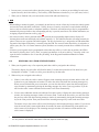
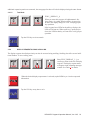
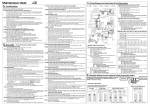
1
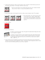
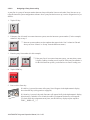
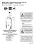
OPERATING INSTRUCTIONS
KP96 / KP97 SERIES KEYPANELS
VERSION 8.3G
WITH EKP96 / EKP97 EXPANSION PANELS
AND LCP-100A LEVEL CONTROL PANEL
ADAM™, ADAM™ CS, AND ZEUS™ INTERCOM SYSTEMS
NUM
1
HDST
Listen
DIR PROD RACK
PL01
IFB4
TD
AD NEWS SAT1
TEL1
TEL2
FLOR CHYR
IS01
IS02
AUD1
IFB
PHONE
PREFIX
4
Clear
TYPE
COPY CW
E-PNL
7
Talk
8
DISP
AUTO
3
ISO
9
MULT
CLR
0
PGM
FUNC
BY
Matrix Intercom System
KP96 / KP97 Keypanels
Listen
DIR
PROD RACK
PL01
IFB4
TD
AD
NEWS
SAT1
TEL1
TEL2
FLOR CHYR
IS01
IS02
AUD1
Clear
Talk
Off
(Talk)
Off
Call
Answer
Talk
BY
Matrix Intercom System
EKP96 / EKP97 Expansion Panels
LCP-100A
LCP-100A Level Control Panel
™
9350-7101-000 V8.3G, 10/97
Volume
6
Dyn Mic
Headset
PUSH
Off
Call
Answer
Incoming Messages
Programing
5
RELAY
EX COPY
Talk
Off
(Talk)
PL
2
SLIST
PROPRIETARY NOTICE
CUSTOMER SUPPORT
The RTS product information and design disclosed herein
were originated by and are the property of Telex Communications, Inc. Telex reserves all patent, proprietary design,
manufacturing, reproduction, use and sales rights thereto,
and to any article disclosed therein, except to the extent
rights are expressly granted to others.
Technical questions should be directed to:
COPYRIGHT NOTICE
Copyright 1997 by Telex Communications, Inc. All rights
reserved. Reproduction in whole or in part without prior
written permission from Telex is prohibited.
UNPACKING AND INSPECTION
Immediately upon receipt of the equipment, inspect the
shipping container and the contents carefully for any discrepancies or damage. Should there be any, notify the
freight company and the dealer at once.
WARRANTY INFORMATION
RTS products are warranted by Telex Communications, Inc.
to be free from defects in materials and workmanship for a
period of three years from the date of sale.
The sole obligation of Telex during the warranty period is to
provide, without charge, parts and labor necessary to remedy covered defects appearing in products returned prepaid
to Telex. This warranty does not cover any defect, malfunction or failure caused beyond the control of Telex, including
unreasonable or negligent operation, abuse, accident, failure
to follow instructions in the Service Manual or the User
Manual, defective or improper associated equipment,
attempts at modification and repair not authorized by Telex,
and shipping damage. Products with their serial numbers
removed or effaced are not covered by this warranty.
To obtain warranty service, follow the procedures entitled
"Procedure For Returns" and "Shipping to Manufacturer for
Repair or Adjustment".
This warranty is the sole and exclusive express warranty
given with respect to RTS products. It is the responsibility
of the user to determine before purchase that this product is
suitable for the user's intended purpose.
ANY AND ALL IMPLIED WARRANTIES,
INCLUDING THE IMPLIED WARRANTY OF
MERCHANTABILITY ARE LIMITED TO THE
DURATION OF THIS EXPRESS LIMITED
WARRANTY.
NEITHER TELEX NOR THE DEALER WHO SELLS
RTS PRODUCTS IS LIABLE FOR INCIDENTAL OR
CONSEQUENTIAL DAMAGES OF ANY KIND.
2 KP96/KP97 Keypanel Operation Manual, Ver. 8.3G
Customer Service Department
RTS/Telex,
2550 Hollywood Way, Suite 207
Burbank, CA 91505 U.S.A.
Telephone: (818) 566-6700
Fax: (818) 843-7953
RETURN SHIPPING INSTRUCTIONS
PROCEDURE FOR RETURNS
If a repair is necessary, contact the dealer where this unit
was purchased.
If repair through the dealer is not possible, obtain a
RETURN AUTHORIZATION from:
Customer Service Department
Telex Communications, Inc.
Telephone: (800) 828-6107
Fax: (800) 323-0498
DO NOT RETURN ANY EQUIPMENT DIRECTLY
TO THE FACTORY WITHOUT FIRST OBTAINING
A RETURN AUTHORIZATION.
Be prepared to provide the company name, address, phone
number, a person to contact regarding the repair, the type
and quantity of equipment, a description of the problem and
the serial number(s).
SHIPPING TO MANUFACTURER FOR REPAIR OR
ADJUSTMENT
All shipments of RTS products should be made via United
Parcel Service or the best available shipper, prepaid. The
equipment should be shipped in the original packing carton;
if that is not available, use any suitable container that is
rigid and of adequate size. If a substitute container is used,
the equipment should be wrapped in paper and surrounded
with at least four inches of excelsior or similar shockabsorbing material. All shipments must be sent to the following address and must include the Return Authorization.
Factory Service Department
Telex Communications, Incorporated
8601 E. Cornhusker Hwy
Lincoln, NE 68505 U.S.A.
Upon completion of any repair the equipment will be
returned via United Parcel Service or specified shipper collect.
Table of Contents
INTRODUCTION · · · · · · · · · · · · · · · · · · · · · · · · · · · · · · · · · · · · · · · · · · · · · · · · 5
DESCRIPTION OF USER CONTROLS AND FEATURES · · · · · · · · · · · · · · · · · · · · · · · · · · 6
BASIC KEYPANEL OPERATION · · · · · · · · · · · · · · · · · · · · · · · · · · · · · · · · · · · · · 7
POWER SWITCH· · · · · · · · · · · · · · · · · · · · · · · · · · · · · · · · · · · · · · · · · · · · · 7
POWER-UP INDICATIONS · · · · · · · · · · · · · · · · · · · · · · · · · · · · · · · · · · · · · · · 7
USING A HEADSET WITH THE KEYPANEL · · · · · · · · · · · · · · · · · · · · · · · · · · · · · 7
VOLUME ADJUSTMENT · · · · · · · · · · · · · · · · · · · · · · · · · · · · · · · · · · · · · · · · 7
PLACING A CALL · · · · · · · · · · · · · · · · · · · · · · · · · · · · · · · · · · · · · · · · · · · · 7
RECEIVING CALLS FROM OTHER KEYPANELS · · · · · · · · · · · · · · · · · · · · · · · · · · 8
ADVANCED OPERATIONS · · · · · · · · · · · · · · · · · · · · · · · · · · · · · · · · · · · · · · · · · · 9
GENERAL · · · · · · · · · · · · · · · · · · · · · · · · · · · · · · · · · · · · · · · · · · · · · · · · · · 9
KEYPAD KEY LABELING · · · · · · · · · · · · · · · · · · · · · · · · · · · · · · · · · · · · · · · · · 9
DISPLAY REQUESTS · · · · · · · · · · · · · · · · · · · · · · · · · · · · · · · · · · · · · · · · · · · · 9
DISPLAY REQUESTS USING KEYPAD SEQUENCES · · · · · · · · · · · · · · · · · · · · · · · · 9
DISPLAY REQUESTS USING SCROLLING · · · · · · · · · · · · · · · · · · · · · · · · · · · · · 11
ASSIGNING SETUP PAGES· · · · · · · · · · · · · · · · · · · · · · · · · · · · · · · · · · · · · · · · 12
PROGRAMMING TALK AND LISTEN KEYS · · · · · · · · · · · · · · · · · · · · · · · · · · · · · · 14
GENERAL · · · · · · · · · · · · · · · · · · · · · · · · · · · · · · · · · · · · · · · · · · · · · · · · 14
PROGRAMMING KEY ASSIGNMENTS USING KEYPAD NUMERIC ENTRY · · · · · · · · · · 14
PROGRAMMING KEY ASSIGNMENTS USING COPY · · · · · · · · · · · · · · · · · · · · · · · 25
PROGRAMMING KEY ASSIGNMENTS USING ALPHA SCROLLING · · · · · · · · · · · · · · 27
CLEARING OR CANCELING A KEY ASSIGNMENT · · · · · · · · · · · · · · · · · · · · · · · · 29
ACTIVATING THE TONE GENERATOR· · · · · · · · · · · · · · · · · · · · · · · · · · · · · · · 31
CALLING A DESTINATION THAT DOES NOT HAVE A talk KEY ASSIGNED · · · · · · · · · 31
KP96/KP97 Keypanel Operation Manual, Ver. 8.3G
3
List of Figures
KP96 / KP97 Keypanels · · · · · · · · · · · · · · · · · · · · · · · · · · · · · · · · · · · · · · · · · · · · · 1
EKP96 / EKP97 Expansion Panels · · · · · · · · · · · · · · · · · · · · · · · · · · · · · · · · · · · · · · · · 1
LCP-100A Level Control Panel · · · · · · · · · · · · · · · · · · · · · · · · · · · · · · · · · · · · · · · · · 1
Figure 1: Keypanel Reference View. (Features may vary, depending on model.)· · · · · · · · · · · · · · · · 5
List of Tables
Table 1: Display Requests Using Scrolling · · · · · · · · · · · · · · · · · · · · · · · · · · · · · · · · · · · 12
4 KP96/KP97 Keypanel Operation Manual, Ver. 8.3G
1
INTRODUCTION
This manual describes the operating procedures for the KP96/KP97 keypanels when used in an ADAM, ADAM CS,
or Zeus Intercom System. The operating procedures are divided into two parts: “Basic Keypanel Operation”
(page 7) which describes how to talk and listen over the intercom system, and “Advanced Operations” (page 9)
which describes how to program key assignments, change setup pages, and display information about the keypanel setup. If you are using a keypanel that has already been setup by a system administrator, you may only need
to refer to the basic operating information. If you need to change the keypanel setup or access other information
about the keypanel setup, you will need to refer to the advanced operation information.
This manual was revised to describe the operation of keypanel firmware version 8.3G. (To find out what version
of firmware is currently installed in your KP96 or KP97 keypanel, see “Display Requests using Scrolling”, page
11). Version 8.3G adds support for the LCP-100A Level Control Panel, and removes the MVOL (master volume)
adjustment. (MVOL let the user adjust the overall gain for an intercom port. It was intended as an adjustment
when a port was being overloaded by too many inputs, but practical experience has revealed that this adjustment
is virtually never required, and that misuse of the adjustment leads to other level and noise problems.) If you need
to make volume adjustments to the listens for individual intercom port or party line assignments, either use the
gain adjust feature (page 12) or consider using LCP-100A Level Control Panels. In some cases, unacceptably high
or low volume levels for particular intercom port assignments may be due to an audio source connected to that
port which is operating at a non-standard level for the intercom system. In such cases, all users at all ports will
hear the audio source at the wrong level. To correct this, it is better to use the Analog Input/Ouput Gain feature,
which is available in the intercom system configuration software.
1
2
3
5
6
7
8
4
NUM
1
HDST
Listen
DIR PROD RACK
PL01
IFB4
TD
AD NEWS SAT1
TEL1
TEL2
FLOR CHYR
IS01
IS02
AUD1
IFB
PHONE
PREFIX
4
Clear
TYPE
COPY CW
E-PNL
7
Talk
8
DISP
AUTO
3
ISO
Volume
6
9
Dyn Mic
Headset
PUSH
Off
Call
Answer
Incoming Messages
Programing
5
RELAY
EX COPY
Talk
Off
(Talk)
PL
2
SLIST
MULT
CLR
0
PGM
FUNC
BY
Matrix Intercom System
9
1.
2.
3.
4.
Designation Strip Holder
Display Window
Listen Keys
Gooseneck Microphone
10
5.
6.
7.
8.
Headset On/Off Key
Programming Keypad and Loudspeaker
External Line Input Volume
Intercom Volume
11
9. Talk Keys
10. Incoming Messages Window
and Key
11. Headset Connector
Figure 1: Keypanel Reference View. (Features may vary, depending on model.)
KP96/KP97 Keypanel Operation Manual, Ver. 8.3G
5
2
DESCRIPTION OF USER CONTROLS AND FEATURES
(See Figure 1 for numbered callouts)
1. Designation Strip Holder: A strip can be inserted here to identify the talk key assignments if required.
2. Display Window: The display window contains a separate indicator for each talk key. The indicators can be
either 4-character, alpha-numeric displays or LED’s, depending on the keypanel model. The alpha-numeric
displays show the names for the destinations (intercom ports, party lines etc.) that have been assigned to the
talk keys (9). These names are defined using the intercom configuration software at a configuration computer.
3. Listen Keys: Listen keys are normally programmed to activate the listen path to the person, party line etc. that
is assigned to the talk key immediately under the listen key. Listen key activation is normally required only
when conversing with certain non-keypanel devices, such as some belt packs or telephone circuits that do not
have data connections to the intercom system. Listen key activation is normally not required when conversing
with another keypanel.
4. Gooseneck Microphone: Pressing any talk key activates the gooseneck microphone. The headset on/off key
(5) must be in the off position to use the gooseneck microphone.
5. Headset On/Off Key: This key is equipped with an LED to indicate the “on” position. When the key is on, the
headset connector (11) is activated, and the gooseneck microphone (4) and loudspeaker (6) are turned off.
6. Programming Keypad and/or Loudspeaker: You use the optional programming keypad to assign destinations
(ports, party lines etc.) to keys and to display information about the keypanel setup. You can also it to display
a destination’s name in the call waiting window and then place a call to that destination using the call waiting
key. This is useful when a destination is not currently assigned to a key, and there are no keys available to
make the assignment. When a keypanel is equipped with a programming keypad, the loudspeaker is located
behind the keypad.
7. External Line Input Volume Control: The inner volume control knob adjusts the headphone or loudspeaker
volume of any input connected to the EXT LINE IN connector on the back of the keypanel (only for keypanels with the optional KP-96-RC Rear Panel Connector Plate).
8. Intercom Volume: The outer volume control knob adjusts headphone and speaker volume for intercom
communications.
9. Talk Keys: These are used to talk to the keypanels, party lines etc. that are indicated on the designation strip
or alpha-numeric display.
10. Incoming Messages Window and Key: The incoming messages window displays the name of a caller when
there is no talk key assigned to the caller. (This is the default operation. The intercom system can also be configured so that the names of all callers display in the incoming messages window. This is accomplished by
changing the position of master controller DIP switch 2. Refer to the intercom stystem installation guide for
further information.) The incoming messages key may be pressed to respond to the caller. The incoming messages key may also be used, along with the programming keypad, to call a keypanel that does not have a talk
key assigned on your keypanel.
11. Dynamic Microphone Headset Connector: A headset with a dynamic microphone may be optionally connected and used in place of the gooseneck microphone and internal speaker.
6 KP96/KP97 Keypanel Operation Manual, Ver. 8.3G
2.1
BASIC KEYPANEL OPERATION
2.1.1
POWER SWITCH
A power switch is located on the back of each keypanel, expansion panel, and level control panel next to the
power cord.
2.1.2
POWER-UP INDICATIONS
Keypanels with Alpha-Numeric Displays: When power is turned on, the talk key displays will first display asterisks (****) then dashes (----). After a few moments, the talk key assignments will display. If no talk key assignments have been programmed, the displays will continue to show dashes. If a keypanel cannot establish
communications with the intercom system, all alpha-numeric displays will continue to show asterisks.
Keypanels with LED Displays: The incoming messages display will first display asterisks (****) then dashes
(----). If a keypanel cannot establish communications with the intercom system, the incoming messages display
will continue to show asterisks (****).
2.1.3
USING A HEADSET WITH THE KEYPANEL
Plug in the headset, then tap the yellow HDST button to turn it on. This will also turn off the keypanel speaker
and gooseneck microphone.
2.1.4
VOLUME ADJUSTMENT
Intercom Volume: Adjust intercom volume using the outer volume control knob on the keypanel.
External Line Input Volume: If an optional external line input is connected, adjust its volume using the inner
volume control knob on the keypanel.
LCP-100A Level Control Panel: If your keypanels and expansion panels are connected to LCP-100A Level
Control Panels, you can adjust the listen level for any key assigned to an intercom port or party line by rotating
the LCP-100A control knob associated with that key.
Gain Adjustment: If your keypanels and expansion panels are not equipped with LCP-100A Level Control Panels, you can still adjust the level for individual intercom ports and party lines using the Gain feature. See page 12.
2.1.5
PLACING A CALL
1. Activate the talk key for the person, party line etc. that you want to talk to:
For momentary talk, hold down the talk key and talk into the microphone. When you
release the key, it will return to the center (off) position.
For hands-free talk, place the talk key in the “up” position and talk into the microphone.
Return the talk key to the center (off) position when finished with your conversation.
KP96/KP97 Keypanel Operation Manual, Ver. 8.3G
7
2. In some cases you may not be able to hear the person, party line etc. to whom you are talking. In such cases,
tap the listen key above the talk key. The listen key LED illuminates when the key is on. (See notes, below.)
3. When you are finished with your conversation, turn off the talk (and listen) keys.
Notes:
• When talking to another keypanel, you normally do not have to activate a listen key because the other keypanel
activates the listen path when it talks back. Usually, however, listen key activation is required when talking to
devices such as some belt packs or telephone interfaces. If desired, selected listen keys may be programmed to
automatically turn on whenever the corresponding talk key is pressed (auto-listen). For further information, see
Assigning a Special Function to a Key, page 17.
• On some occasions, when a particular talk key is pressed, the corresponding alpha-numeric display will
alternate between the normal display and a double asterisk (**). This indicates that the call cannot currently be
placed. There are two occasions when this happens. The first is when the key is assigned to an IFB and another
keypanel with a higher IFB priority is currently using the IFB. The second is when the talk key is assigned to a
person, party line, etc. of a remote intercom system, and there are currently no trunk lines available to route the
call.
• If desired, your keypanel may be programmed so that when any talk key is left in the on position, the LED in
the listen key directly above it will “wink” to remind you that there is an active talk key. Listen key wink is set
up at the time of installation. See “Listen Key Winking” in the Keypanel Installation Manual for further
information.
2.1.6
RECEIVING CALLS FROM OTHER KEYPANELS
1. When your keypanel or any of its expansion panels has a talk key assigned to the caller(s):
The talk key display for each caller will flash for about 15 seconds and each caller will be heard over your
loudspeaker or headset1. To talk to a caller, press the talk key for that caller.
2. When no keys are assigned to the caller(s):
a. If there is one caller, the caller’s name will appear in the incoming messages window and the caller will
be heard over your loudspeaker or headset. To talk to the caller, hold down the incoming messages key.
When you are finished with your conversation, you can clear the caller’s name from the incoming messages window by momentarily placing the incoming messages key in the Clear (up) position. If you do
not clear the caller’s name within about 90 seconds it will clear automatically.
b. If one or more additional stations call while the first caller’s name is displayed in the incoming messages
window, the incoming messages window will start to flash. To talk to the next caller, you must first clear
the previous caller from the incoming messages window by momentarily placing the incoming messages
key in the Clear position. Then press down on the incoming messages key to talk to the next caller.
The names of up to four callers will be stored for display in the incoming messages window. If you do not
clear the current caller’s name within about 90 seconds, the name will automatically clear and the next
caller’s name will be displayed. The incoming messages window will continue to blink until the last
caller’s name is displayed.
1
The caller’s name may also appear in the incoming messages window if Master Controller DIP switch 2 has been set to
the “On” position in the intercom matrix frame. In this case, steps 2a and 2b also apply.
8 KP96/KP97 Keypanel Operation Manual, Ver. 8.3G
3
ADVANCED OPERATIONS
3.1
GENERAL
The intercom system’s configuration computer and software are the primary tools for creating and saving intercom system configurations. If your keypanel is equipped with a programming keypad, you can also change settings for your keypanel from the keypad, provided restrictions have not been imposed using the intercom system
configuration software. If you try to program a restricted key or function, the programming will be ignored.
Setup changes made at the keypanel are immediately uploaded to the intercom system and become part of the
intercom system configuration. These changes will be retained during loss of power, but if an additional backup
record is desired, the changes should be saved to disk using the intercom system configuration software.
3.2
KEYPAD KEY LABELING
Notes:
• The CLR key is used to cancel a program sequence. It is a good idea to start any program sequence by first
tapping this key to clear any uncompleted programming sequence.
• The white labels on some keys indicate programming sequences that start by simply tapping that key. For
example, to program a party line, you always start by tapping the white “PL” key.
• The red labels on some keys indicate programming sequences that start by tapping the FUNC key followed by a
red-labeled key. For example, to program a special list, you always start by tapping FUNC__ SLIST (tap the
FUNC key, then tap the red SLIST key).
• Keys with numbers 0-9 are used to enter panel numbers, party line numbers etc.
• The PGM key is generally pressed immediately after a programming sequence and immediately before pressing
a talk or listen key when making key assignments. This key is used to tell the keypanel that you have completed
a key sequence and now wish to assign a key.
3.3
DISPLAY REQUESTS
Display requests let you view information about the keypanel’s current configuration. You can display information by two methods: either by entering sequences on the programming keypad, or by scrolling the names of display requests in the incoming messages window and then selecting the desired display request. The scrolling
method also gives you access to additional features that are not available with the keypad sequences. The following paragraphs discuss these two methods.
3.3.1
DISPLAY REQUESTS USING KEYPAD SEQUENCES
MULT
E-PNL
FUNC
DISPLAY
0
All display request sequences start with FUNC__DISPLAY
8
KP96/KP97 Keypanel Operation Manual, Ver. 8.3G
9
3.3.1.1
Keypanel Identification
MULT
E-PNL
NUM
FUNC
DISPLAY
SLIST
0
8
1
FUNC__DISPLAY__1
This sequence displays the panel number of the
keypanel in the incoming messages window for
about 2 seconds.
☞ A false reading can be given if the keypanel’s dip switches are incorrectly set.
3.3.1.2
Level 2 Talk Key Assignments For Stacked Talk Keys
A stacked talk key activates two types of communication at once. For example, a stacked talk key could
simultaneously activate audio output to a transmitter and key the transmitter using a relay. The audio output is called the level l assignment and the relay is called the level 2 assignment. Normally, the level l talk
key assignment is displayed on the keypanel. To briefly display the level 2 assignments enter:
MULT
E-PNL
PL
FUNC
DISPLAY
IFB
0
3.3.1.3
8
2
FUNC__DISPLAY__2
This sequence displays all level 2 talk key
assignments for about 10 seconds (keypanels
with alpha-numeric talk key displays only).
“LEV2” displays in the incoming messages
window.
Listen Key Assignments
MULT
E-PNL
AUTO
FUNC
DISPLAY
ISO
0
3.3.1.4
8
3
FUNC__DISPLAY__3
This sequence displays all listen key assignments for about 10 seconds (keypanels with
alpha-numeric talk key displays only). “LSTN”
displays in the incoming messages window.
Keypanel And Expansion Panel Setup Page Numbers
Each keypanel has four setup pages. Each setup page defines a complete set of talk and listen key assignments for one panel. One setup page is required for the main keypanel, and one is required for each
expansion panel connected to the main keypanel.
MULT
E-PNL
E-PNL
FUNC
DISPLAY
DISPLAY
0
8
FUNC__DISPLAY__E-PNL
8
When you enter this sequence, the incoming messages window displays “M_n”, where M indicates the
main keypanel and n indicates the setup page number. Next, if there is an expansion panel connected,
“E1-n” is displayed, where E1 indicates expansion panel 1 and n indicates the setup page number. If
10 KP96/KP97 Keypanel Operation Manual, Ver. 8.3G
additional expansion panels are connected, the setup pages for these will also be displayed using the same format.
3.3.1.5
Test Mode
MULT
E-PNL
MULT
FUNC
DISPLAY
FUNC
0
8
FUNC__DISPLAY__0
0
When you enter this sequence, all alpha-numeric displays show a % symbol. When a talk key is pressed up
or down, the display changes to “OK” verifying proper
key operation.
If the keypanel uses LEDs for the talk key displays, the
LEDs will all turn on. When a talk key is pressed up or
down, the LED for that key will turn off to verify proper
operation.
Tap the CLR key to exit test mode.
3.3.2
DISPLAY REQUESTS USING SCROLLING
The display requests described previously can also be accessed using scrolling. Scrolling also offers several additional features. To use scrolling, enter:
MULT
E-PNL
FUNC
DISPLAY
0
PGM
8
6
9
Enter FUNC_DISPLAY_ ↑↓ to
scroll up or down in the list of display
requests. The display request names
will appear in the incoming messages
window. See Table 1 for details.
When the desired display request name is selected, tap the PGM key to view the requested
information.
Tap the CLR key at any time to exit.
KP96/KP97 Keypanel Operation Manual, Ver. 8.3G
11
Table 1: Display Requests Using Scrolling
NAME
DESCRIPTION
ID
Briefly displays the panel number of the keypanel (same as FUNC_DISPLAY_1).
LEV2
Briefly displays the level 2 talk key assignments (same as FUNC_DISPLAY_2).
LSTN
Briefly displays listen key assignments (same as FUNC_DISPLAY_3).
NAME
Gets a list of all crosspoints to this keypanel which are closed and displays the list in the incoming messages
window. (If there are no crosspoints closed “N/A” will briefly display.) Use the ↑↓ keys to scroll up or down
the list. You may press the incoming messages key to talk back to the selected crosspoint.
TYPE
Briefly displays the type of communication (point-to-point, party line etc.) for all level 1 talk key assignments.
MTX
Briefly displays the intercom system (matrix) names for all level 1 talk key assignments. If there is only one
intercom system, the word “LOCL” displays to indicate “local matrix”.
TONE
Turns on the keypanel’s tone generator (same as FUNC_DISPLAY_7). Tap CLR to turn the tone generator
off. (See Activating the Tone Generator, page 31.)
EPNL
Briefly displays the setup page numbers of the main keypanel and any connected expansion panels (same
as FUNC_DISPLAY_8).
V8.3G
Displays current software version. (The PGM key causes no further action.)
GAIN
Used to adjust listen gain for a point-to-point or party line listen key. After selecting GAIN, tap a listen key.
After a few seconds, the gain level for that key will display. Use the ↑↓ keys to change the gain level.
TEST
Enters test mode (same as FUNC_DISPLAY_0).
☞ Tap CLR at any time to return to the normal incoming messages window display.
3.4
ASSIGNING SETUP PAGES
Each keypanel has 4 setup pages, and each setup page contains 16 key assignments. One setup page is assigned to
the main keypanel, and one is assigned to each expansion panel. Up to 3 expansion panels can therefore be connected. Or, if less than 3 expansion panels are connected, the extra setup pages can be used as alternate configurations for the main keypanel. This means that you can completely change the keypanel’s key assignments by
changing the setup page that is assigned. Assign setup pages as follows:
1. On the main keypanel, tap the E-PNL key.
E-PNL
8
DISPLAY
12 KP96/KP97 Keypanel Operation Manual, Ver. 8.3G
2. Select setup page 1-4 (4 in this example).
PHONE
4
RELAY
3. Tap the PGM key.
PGM
4. On the desired keypanel or expansion panel, press any talk or listen key. If the panel has alpha-numeric displays, the new key assignments should appear in a few moments.
Notes
• The same setup page cannot be assigned to more than one panel. If a setup page is already assigned to a panel,
you must change that panel’s assignment before you can use the same setup page for another panel.
• If a panel will not accept a setup page assignment, this feature may have been restricted by the intercom system
configuration software.
• On expansion panels only, you can clear the page assignment by entering E-PNL__0__PGM, then pressing any
key on the expansion panel.
E-PNL
MULT
DISPLAY
FUNC
8
0
PGM
KP96/KP97 Keypanel Operation Manual, Ver. 8.3G
13
3.5
PROGRAMMING TALK AND LISTEN KEYS
3.5.1
GENERAL
There are three methods to program talk and listen keys. These methods are summarized below and explained on
the following pages.
Key Assignment using Keypad Numeric Entry: Using this method, you enter the panel number, party line
number etc. that you wish to assign to a key. This method requires that you know the number (not the name)
of the port, party line etc. that you wish to assign. Since most users do not have access to this information, this
method of key assignment is not recommended.
Key Assignment by Copying an Assignment: Using this method, you can copy an assignment from one key
to another. You can also use this method to transfer an incoming call to a talk key and/or listen key.
Key Assignment using Alpha Scrolling: Using this method, you scroll through a list in the incoming messages window and pick the alpha-numeric name of the panel, party line etc. that you wish to assign to a key.
Then you copy that name to a key. If descriptive names have been assigned (using the intercom system configuration software) alpha scrolling is easiest to use.
Notes
• You can individually program each talk and listen if desired. However, in most cases, we recommend that you
use one of the special function assignments for the listen keys (see “Assigning a Special Function to a Key”,
page 17). When you set a listen key for one of the special function assignments, you can change the
corresponding talk key assignment to anything you want, and the listen key will take on the same assignment
automatically.
• When you program a talk key, the name of the port, party line etc. that you have programmed will appear in the
alpha-numeric display above that key. If a listen key is programmed, the alpha-numeric display below that key
will briefly display the assignment, and after a few seconds the talk key assignment for that key will reappear.
To check listen key assignments at any time, enter FUNC__DISPLAY__3 on the keypad.
3.5.2
PROGRAMMING KEY ASSIGNMENTS USING KEYPAD NUMERIC ENTRY
☞ When using numeric entry, each programming step must be completed within 4-5 seconds. Otherwise, the
sequence will automatically be cleared.
3.5.2.1
Point-to-Point Key Assignments
You use point-to-point key assignment when you want to program a key to talk/listen to a specific keypanel, belt
pack etc. To program a point-to-point key assignment:
1. Tap the NUM key.
NUM
1
SLIST
14 KP96/KP97 Keypanel Operation Manual, Ver. 8.3G
2. If the keypanel, belt pack etc. that you want to assign to a key is located in a remote intercom system, enter
the intercom system number (7 for example). Otherwise, skip to step 3.
COPYCW
7
☞ Intercom system numbers are the numbers that appear in the “Icm” column in CStrunk
when you select “Names” or “Setup” from the Intercoms menu.
EX COPY
3. Enter the panel number of the keypanel, belt pack etc. that you want to assign to a key (37 for example:)
MULT
AUTO
COPYCW
FUNC
ISO
EX COPY
0
3
7
☞ If the panel number is for a remote intercom system,
you must always enter 3 digits by adding leading
zeros as shown. If the panel number is for the local
intercom system, you do not have to enter any leading zeros.
4. Tap the PGM key.
PGM
5. Press a talk (or listen) key.
If a talk key is pressed, the panel’s name will appear in the alpha-numeric display above that
key (on keypanels so equipped).
If a listen key is pressed, the panel’s name will appear briefly in the alpha-numeric display
below that key, and after a few seconds, the talk key assignment for that key will reappear.
(To check listen key assignments at any time, use the listen key display request sequence:
FUNC__DISPLAY__3.)
☞ If a key will not accept an assignment, the port that you are trying to assign may have been restricted (not
enabled) by the intercom system configuration software. The intercom system configuration software can also
be used to restrict individual keypanel keys to prevent key assignment.
KP96/KP97 Keypanel Operation Manual, Ver. 8.3G
15
3.5.2.2
Assigning a Party Line to a Key
A party line is a group of intercom stations that can always talk and/or listen to each other. Party lines are set up
using the intercom system configuration software. Once a party line has been set up, it can be assigned to a key as
follows:
1. Tap the PL key.
PL
2
IFB
2. If the party line is located in a remote intercom system, enter the intercom system number (7 in the example).
Otherwise, skip to step 3.
COPYCW
7
☞ Intercom system numbers are the numbers that appear in the “Icm” column in CStrunk
when you select “Names” or “Setup” from the Intercoms menu.)
EX COPY
3. Enter the party line number (4 in this example).
MULT
PHONE
FUNC
RELAY
0
4
☞ If the party line is in a remote intercom system, you must always enter
2 digits by adding a leading zero if required. If the party line number is
for the local intercom system, you do not have to enter a leading zero.
4. Tap the PGM key.
PGM
5. Press a talk or listen key.
If a talk key is pressed, the name of the party line will appear in the alpha-numeric display
above that talk key (on keypanels so equipped).
If a listen key is pressed, the partly line name will appear briefly in the alpha-numeric display
below that key, and after a few seconds, the talk key assignment for that key will reappear.
(To check listen key assignments at any time, use the listen key display request sequence:
FUNC__DISPLAY__3.)
16 KP96/KP97 Keypanel Operation Manual, Ver. 8.3G
Notes
• If a key will not accept an assignment, the party line that you are trying to assign may have been restricted (not
enabled) by the intercom system configuration software. The intercom system configuration software can also
be used to restrict individual keypanel keys to prevent key assignments.
• If desired, you can program the listen key with the auto-listen special function so that it is automatically
activated when the talk key is pressed. See “Assigning a Special Function to a Key,” below, for further
information.
3.5.2.3
Assigning a Special Function to a Key
Special Functions are additional key assignments that can simplify communications. There are five special functions available. Each special function has a default two-character name for display purposes:
Name
Description
AF
Auto Follow (for listen keys only): Auto follow causes a listen key’s assignment to always be the same
as the talk key directly below it. Thus, if you reassign the talk key, you do not also have to reassign
the listen key. You can manually activate an auto-follow listen key independently of the talk key. If you
want auto-activation (or deactivation) use one of the other key assignments, below.
AL
Auto Listen (for listen keys only): This assignment works like auto follow, except that listen is automatically activated when the talk key is pressed. It is sometimes a good assignment for use with party
lines or other non-keypanel devices that do not have talk-back control of matrix crosspoints.
AM
Auto Mute (for listen keys only): This assignment works like auto follow, except that listen is automatically muted when the talk key is pressed. Auto mute is useful for talking to devices which echo your
voice back to you, as it prevents feedback.
AR
Auto Reciprocal (for listen keys only): This assignment forces you to continuously listen to whatever is
assigned to the talk key. It is used commonly on keypanels which are not equipped with listen keys to
allow listening to party lines. It is also useful to force listening when it is desirable to have an operator
continuously hear a party line or other source.
AC
All Call (for talk keys only): When a talk key is programmed for All Call, pressing the key will also activate all talk keys to the left of the All Call key (up to, but not including another All Call key).
To assign a special function to a key:
1. Tap the AUTO key.
AUTO
3
ISO
2. Select a special function:
KP96/KP97 Keypanel Operation Manual, Ver. 8.3G
17
NUM
tap 1 for Auto Listen, or...
1
SLIST
PL
tap 2 for Auto Follow, or...
2
IFB
AUTO
tap 3 for Auto Mute, or...
3
ISO
PHONE
tap 4 for Auto Reciprocal, or...
4
RELAY
PREFIX
tap 5 for All Call.
5
TYPE
3. After selecting a special function, tap the PGM key.
PGM
4. Press a listen key (for all features except All Call) or a talk key (All Call only).
If a talk key is pressed for All Call, “AC” will appear in the alpha-numeric display above the
key (on keypanels so equipped). If a listen key is pressed, the name of the selected auto function will briefly appear in the display below the key.
18 KP96/KP97 Keypanel Operation Manual, Ver. 8.3G
☞ If a key will not accept an assignment, the special function that you are trying to assign may have been
restricted (not enabled) by the intercom system configuration software. The intercom system configuration
software can also be used to restrict individual keypanel keys to prevent key assignment.
☞ Special functions are always assigned in the local intercom system only. However, this does not mean that
they cannot be used with remote key assignments. For example, you can program a talk key to talk to a
remote party line and then program the listen key using auto-listen on the local intercom. Pressing the talk key
will automatically activate listening for the remote party line.
3.5.2.4
Assigning a Special List to a Key
Intercom stations, party lines etc. are always assigned to a special list using the intercom system configuration
software. Once a special list has been set up, you may access all personnel on the list using a talk and/or listen key
on your keypanel. Special lists are typically used for paging or monitoring selected groups of people. To assign a
special list to a key:
1. Tap the FUNC key.
MULT
0
FUNC
2. Tap the SLIST key.
NUM
1
SLIST
3. If the special list is located in a remote intercom system, enter the intercom system number (5 in the example). Otherwise, skip to step 4.
PREFIX
5
☞ Intercom system numbers are the numbers that appear in the “Icm” column in CStrunk
when you select “Names” or “Setup” from the Intercoms menu.
TYPE
KP96/KP97 Keypanel Operation Manual, Ver. 8.3G
19
4. Enter the special list number (4 in this example).
MULT
PHONE
FUNC
RELAY
0
☞ If the special list is in a remote intercom system, you must always
4
enter 2 digits by adding a leading zero if required. If the special list is
in the local intercom system, you do not have to enter a leading zero.
5. Tap the PGM key.
PGM
6. Press a talk (or listen) key.
If a talk key is pressed, the name of the special list will appear in the alpha-numeric display
above that talk key (on keypanels so equipped).
If a listen key is pressed, the special list name will appear briefly in the alpha-numeric display
below that key, and after a few seconds, the talk key assignment for that key will reappear.
(To check listen key assignments at any time, use the listen key display request sequence:
FUNC__DISPLAY__3.)
☞ If a key will not accept an assignment, the special list that you are trying to assign may have been restricted
(not enabled) by the intercom system configuration software. The intercom system configuration software can
also be used to restrict individual keypanel keys to prevent key assignment.
3.5.2.5
Assigning an IFB to a Key
IFB (Interrupt Foldback) is a special type of communication in which an intercom port’s output normally hears an
audio program source connected to some intercom input port. The intercom output port is called the IFB output
and the program input port is called the IFB input. When a keypanel operator talks to the IFB output, the IFB
input is interrupted to permit the keypanel operator to be heard clearly by the person at the IFB output. The IFB
input is restored when the keypanel operator is finished talking. IFB’s are setup by defining the IFB inputs and
outputs using the intercom system configuration software. Once an IFB is setup, you may assign it to a key at
your keypanel (provided that IFB assignment has not been restricted or disabled in the intercom system configuration software). Assign an IFB to a key as follows:
1. Tap the FUNC key.
MULT
0
FUNC
20 KP96/KP97 Keypanel Operation Manual, Ver. 8.3G
2. Tap the IFB key.
PL
2
IFB
3. If the IFB is located in a remote intercom system, enter the intercom system number (5 in this example). Otherwise, skip to step 4.
PREFIX
☞ Intercom system numbers are the numbers that appear in the “Icm” column in CStrunk
when you select “Names” or “Setup” from the Intercoms menu.
5
TYPE
4. Enter the IFB number (2 in this example).
MULT
PL
FUNC
IFB
2
0
☞ If the IFB is in a remote intercom system, you must enter 2 digits by
adding a leading zero if required. If the IFB is in the local intercom
system, you do not have to enter a leading zero.
5. Tap the PGM key.
PGM
6. Press a talk key.
The name of the IFB will appear in the alpha-numeric display above that talk key (on keypanels so equipped).
☞ If a key will not accept an assignment, the IFB that you are trying to assign may have been restricted (not
enabled) by the intercom system configuration software. The intercom system configuration software can also
be used to restrict individual keypanel keys to prevent key assignment.
KP96/KP97 Keypanel Operation Manual, Ver. 8.3G
21
3.5.2.6
Assigning an ISO to a Key
ISO is a special type of communication used with party lines that have been setup using the intercom system’s
party line feature. ISO is used when a keypanel operator wants to isolate a member of a party line to give instructions without interference from other communications on the party line. Additionally, ISO’s can be setup so that
the person at the keypanel is also cutoff from all other intercom communications during ISO activation. ISO’s are
typically used in a television broadcast environment to provide directions to specific cameras operating on a camera party line. ISO’s are setup using the intercom system configuration software. Once an ISO has been setup you
may assign a key on your keypanel to use the ISO (unless restrictions have been imposed, using the intercom system configuration software, to prevent key assignment from keypanels). Assign an ISO to a key as follows:
1. Tap the FUNC key.
MULT
0
FUNC
2. Tap the ISO key.
AUTO
3
ISO
3. If the ISO is located in a remote intercom system, enter the intercom system number (5 in this example). Otherwise, skip to step 4.
PREFIX
5
☞ Intercom system numbers are the numbers that appear in the “Icm” column in CStrunk
when you select “Names” or “Setup” from the Intercoms menu.
TYPE
4. Enter the ISO number (2 in this example).
MULT
PL
FUNC
IFB
0
2
☞ If the ISO is in a remote intercom system, you must enter 2 digits by
adding a leading zero if required. If the ISO is in the local intercom
system, you do not have to enter a leading zero.
22 KP96/KP97 Keypanel Operation Manual, Ver. 8.3G
5. Tap the PGM key.
PGM
6. Press a talk key.
The name of the ISO will appear in the alpha-numeric display above that talk key (on keypanels so equipped).
☞ If a key will not accept an assignment, the ISO that you are trying to assign may have been restricted (not
enabled) by the intercom system configuration software. The intercom system configuration software can also
be used to restrict individual keypanel keys to prevent key assignments.
3.5.2.7
Assigning a Relay to a Key
The relay feature works with the 16 GPI outputs of an optional UIO-256 Universal Input / Output Frame. The
relay feature also works with the 8 GPI outputs of your intercom system (available at J27 on a Zeus Frame, J903
on an ADAM CS Frame, and J11 on the XCP-ADAM-MC Master Controller Breakout Panel in an ADAM Intercom System). You can assign a keypanel key to control a GPI output from any of these devices, and then use that
key and output to control an external device. For example, you could use a keypanel key to control lighting. Or,
you could assign a relay as a level 2 talk key assignment in a stacked talk key arrangement to both send audio and
key a device, such as a paging amplifier or a 2-way radio. To use a GPI output in a stacked talk key arrangement,
see See “Programming a Stacked Talk Key”, page 24. To assign a GPI output as a standard key assignment, use
the following procedure:
1. Tap the FUNC key.
MULT
0
FUNC
2. Tap the RELAY key.
PHONE
4
RELAY
3. If the relay is located in a remote intercom system, enter the intercom system number (5 in this example).
Otherwise, skip to step 4.
KP96/KP97 Keypanel Operation Manual, Ver. 8.3G
23
PREFIX
☞ Intercom system numbers are the numbers that appear in the “Icm” column in CStrunk
when you select “Names” or “Setup” from the Intercoms menu.
5
TYPE
4. Enter the relay number (2 in this example).
MULT
PL
FUNC
IFB
2
0
☞ If the relay is in a remote intercom system, you must enter 2 digits by
adding a leading zero if required. If the relay is in the local intercom
system, you do not have to enter a leading zero.
5. Tap the PGM key.
PGM
6. Press a talk (or listen) key.
If a talk key is pressed, the name of the relay will appear in the alpha-numeric display above
that talk key (on keypanels so equipped). If a listen key is pressed, the relay name will appear
briefly in the alpha-numeric display below that key, and after a few seconds, the talk key
assignment for that key will reappear. (To check listen key assignments at any time, use the
listen key display request sequence: FUNC__DISPLAY__3.)
☞ If a key will not accept an assignment, the relay that you are trying to assign may have been restricted (not
enabled) by the intercom system configuration software. The intercom system configuration software can also
be used to restrict individual keypanel keys to prevent key assignments.
3.5.2.8
Programming a Stacked Talk Key
A stacked talk key activates two types of communication at once. For example, a stacked talk key could simultaneously activate audio output to a transmitter and key the transmitter using a relay. The audio output is called a
level 1 assignment and the relay is called a level 2 assignment. Anything that could be programmed as a normal
talk key assignment may be stacked (except that all-call cannot be assigned to level 2). To program a stacked talk
key:
1. Program level 1 exactly as you would any talk key assignment.
2. Program level 2 like any talk key assignment, except enter 00 before the key sequence.
Example: Assign panel number 45 of the local intercom as the level 1 key assignment and assign relay 5 of the
local intercom as level 2:
24 KP96/KP97 Keypanel Operation Manual, Ver. 8.3G
LEVEL 1: PANEL 45
NUM
PHONE
PREFIX
SLIST
1
4
RELAY
5
TYPE
PGM
MULT
MULT
MULT
PHONE
PREFIX
FUNC
FUNC
FUNC
RELAY
TYPE
LEVEL 2: RELAY 5
0
0
0
4
5
If the keypanel has alpha-numeric displays, the level 2 key assignment will
display briefly after the talk key is pressed.
PGM
☞ If a key will not accept an assignment, the destination (relay, intercom port etc.) that you are trying to assign
may have been restricted (not enabled) by the intercom system configuration software. The intercom system
configuration software can also be used to restrict individual keypanel keys to prevent key assignment.
3.5.2.9
Clearing a Level 2 Talk Key Assignment
Clear a level 2 assignment by clearing the level 1 assignment. See “Clearing or Canceling a Key Assignment”,
page 29.
3.5.3
PROGRAMMING KEY ASSIGNMENTS USING COPY
There are two ways to copy key assignments: 1) you can copy a call from the incoming messages window to a
key; or 2) you can copy one key assignment to another key.
3.5.3.1
Copying a Call from the Incoming Messages Window to a Key
1. While the caller’s name is displayed in the incoming messages window, tap the COPY CW key.
COPYCW
7
EX COPY
KP96/KP97 Keypanel Operation Manual, Ver. 8.3G
25
2. Press the talk or listen key to which the call is to be copied.
If a talk key is pressed, the name of the key assignment that you are copying will appear in
the alpha-numeric display above that talk key (on keypanels so equipped).
If a listen key is pressed, the copied name will appear briefly in the alpha-numeric display
below that key, and after a few seconds, the talk key assignment for that key will reappear.
(To check listen key assignments at any time, use the listen key display request sequence:
FUNC__DISPLAY__3.)
3. Repeat the steps to assign additional keys.
☞ If a key will not accept an assignment, the destination (intercom port, party line etc.) that you are trying to
assign may have been restricted (not enabled) by the intercom configuration software. The intercom system
configuration software can also be used to restrict individual keypanel keys to prevent key assignment.
3.5.3.2
Copying One Key Assignment to Another Key
1. Tap the FUNC key.
MULT
0
FUNC
2. Tap the EX COPY key.
COPYCW
7
EX COPY
3. Press the talk or listen key from which you wish to copy.
4. Press the talk or listen key to which you wish to copy.
If a talk key is pressed, the name of the key assignment that you are copying will appear in
the alpha-numeric display above that talk key (on keypanels so equipped). If a listen key is
pressed, the copied name will appear briefly in the alpha-numeric display below that key, and
after a few seconds, the talk key assignment for that key will reappear. (To check listen key
assignments at any time, use the listen key display request sequence:
FUNC__DISPLAY__3.)
26 KP96/KP97 Keypanel Operation Manual, Ver. 8.3G
5. Repeat the steps to assign additional keys.
☞ If a key will not accept an assignment, the destination (intercom port, party line etc.) that you are trying to
assign may have been restricted (not enabled) by the intercom system configuration software. The intercom
system configuration software can also be used to restrict individual keypanel keys to prevent key assignment.
3.5.4
PROGRAMMING KEY ASSIGNMENTS USING ALPHA SCROLLING
Alpha scrolling lets you scroll through a list of names of panels, party lines etc. in the incoming messages window. Once the desired name is displayed in the window, you can copy it to a key. There are four scrolling modes:
intercom, type, prefix and single-step. The following example demonstrates their use.
Example: Assign a port to a key using the various scrolling modes.
1. If the port is located in a remote intercom system, tap FUNC ↑ or FUNC ↓ to enter intercom scroll mode and
scroll up or down the list of intercoms in the incoming messages window. Otherwise, skip to step 2.
MULT
0
FUNC
or
6
MULT
0
FUNC
9
☞ You cannot scroll for remote intercom systems until trunking has been setup using CStrunk and the intercom
system configuration software.
2. When the desired intercom system name is displayed, or when making an assignment in the local intercom
system, tap FUNC__TYPE to activate type scroll mode.
MULT
PREFIX
FUNC
TYPE
0
5
3. Use the ↑↓ keys to select the desired type of communication in the incoming messages window. (See the
abbreviations which follow.) In this example, you would scroll to “P-P”.
6
9
KP96/KP97 Keypanel Operation Manual, Ver. 8.3G
27
☞ The following abbreviations are used for types of communication:
P-P
Point-to-Point
PL
Party Line
IFB
IFB
SPCL Special List
RLY
Relay
ISO
ISO
4. When the desired type of communication has been selected, press PGM to retrieve the requested list. Pressing
PGM also exits type scroll mode and places the keypanel in single-step scroll mode.
PGM
☞ In some cases, “WAIT” may display briefly while the requested list is being retrieved.
5. When the keypanel is in single-step scroll mode it may take a long time to scroll to the desired name (this is
particularly true of point-to-point lists). To speed up the process, you can use prefix scroll mode. Prefix scrolling mode scrolls through a list in alpha-numeric order, but displays only the first occurrence of each twocharacter prefix. For example, if your intercom system had users 1CAM, 2CAM, 3CAM, 1DIR and 2DIR,
prefix scrolling would display 1CAM followed by 1DIR. Once you locate a desired two-character prefix
using prefix scroll, you can switch back to single-step scrolling to make your final selection. Tap PREFIX to
enter prefix scroll mode, then use the arrow keys to scroll.
PREFIX
5
TYPE
9
6
As you scroll, the currently selected name will be displayed in the incoming messages window.
6. When you locate a name with the same first two characters as the name you are looking for, tap the PGM key
to return to single-step scrolling mode, then use the arrow keys to make your final selection.
☞ You can return to prefix scroll mode again by pressing PREFIX.
PGM
☞ If you cannot locate the name that you are looking for in a scroll list, that name may
have been restricted (not enabled) using the intercom system configuration software. In
this case, you will not be able to make the key assignment, and you will have to talk to
the intercom system administrator to make the change for you.
7. Copy the selected port to a talk or listen key:
28 KP96/KP97 Keypanel Operation Manual, Ver. 8.3G
a. Tap COPY CW
COPYCW
7
EX COPY
b. Press the talk or listen key you want to copy to.
If a talk key is pressed, the name of the key assignment that you are copying will appear in
the alpha-numeric display above that talk key (on keypanels so equipped).
If a listen key is pressed, the copied name will appear briefly in the alpha-numeric display
below that key, and after a few seconds, the talk key assignment for that key will reappear.
(To check listen key assignments at any time, use the listen key display request sequence:
FUNC__DISPLAY__3.)
c. Repeat steps a and b to copy the assignment to additional keys.
☞ If a key will not accept an assignment, the destination (intercom port, party line etc.) that you are trying to
assign may have been restricted (not enabled) by the intercom system configuration software. The intercom
system configuration software can also be used to restrict individual keypanel keys to prevent key assignment.
3.5.5
CLEARING OR CANCELING A KEY ASSIGNMENT
There are two ways to clear a key assignment:
3.5.5.1
Method 1: Clearing the Incoming Messages Window and Copying it to a Key
1. Clear the incoming messages window, if necessary, by momentarily placing the incoming messages key in
the up position.
2. Tap the COPY CW key.
COPYCW
7
EX COPY
KP96/KP97 Keypanel Operation Manual, Ver. 8.3G
29
3. Tap the key to be cleared. This can be either a talk or listen key.
☞ If a key will not clear, restrictions may have been imposed using the intercom system configuration software.
3.5.5.2
Method 2: Copying a Blank Key Assignment to the Key that You want to Clear
1. Tap the FUNC key.
MULT
0
FUNC
2. Tap the EX COPY key.
COPYCW
7
EX COPY
3. Tap the blank key.
4. Tap the key that you want to copy to. This can be either a talk or a listen key.
☞ If the key will not clear, it may have been restricted using the intercom system configuration software.
30 KP96/KP97 Keypanel Operation Manual, Ver. 8.3G
3.5.6
ACTIVATING THE TONE GENERATOR
You can check a keypanel’s audio send and receive paths to and from the matrix using the built-in tone generator.
To activate the tone generator, enter:
MULT
E-PNL
COPYCW
FUNC
DISPLAY
EX COPY
0
8
FUNC__DISPLAY__7
7
To check the audio path to and from the intercom matrix, assign a talk key on the keypanel to talk to itself. When
you activate the talk key, you should be able to hear the tone from the keypanel speaker. To turn off the tone generator, press the CLR key.
3.5.7
CALLING A DESTINATION THAT DOES NOT HAVE A TALK KEY ASSIGNED
Occasionally, you may need to talk to a keypanel that does not have a key assigned on your keypanel. You can
create a temporary talk key using the incoming messages key. Use the scrolling modes previously described, and
when the desired name is displayed in the incoming messages window, press the incoming message key to talk.
(Note that this procedure is not recommended for use with belt packs or party lines, since you won’t be able to
hear them.)
KP96/KP97 Keypanel Operation Manual, Ver. 8.3G
31