1
Operating Instructions
Construction Site Traffic
Signal System MPB 3200
GB
General explanation for construction site
traffic signal systems
SIGNAL SAFETY FEATURE
The regulations of VDE, TL-LSA 97 and RiLSA describe among others the
use of portable construction site traffic signal systems.
The above regulations stipulate that no signal safety feature as per RiLSA and
VDE 0832 is necessary e.g. for short-term construction sites (up to four
weeks) which are clearly organised (clearance distance up to 50 m) with
alternating one-way traffic control and a clearance speed of up to 30 km/h,
insofar as the corresponding authorities have not imposed any stricter
conditions or requirements.
All other construction site traffic signal systems used for controlling traffic at Tjunctions, crossroads or pedestrian crossings must be equipped with a signal
safety feature as per RiLSA and VDE 0832 and fulfil TL-LSA 97.
This signal safety feature requires a feedback message which can be
transmitted by radio or cable. Radio-controlled traffic signal systems are
equipped with top quality radio modules tested and certified to CE.
Under ideal conditions, the radio signals have a range of up to 2000 m.
Peter Berghaus GmbH produces and supplies construction site traffic
signal systems with and without signal safety feature.
3
Caution, important information:
Please note that permission is required to use radio traffic signal
systems in most countries, so please consult your national regulations.
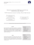
Table for adjusting the interim times (clearance times)
Interim times tz [s] (as per RiLSA)
Clearance
distance [m]
50
100
150
200
250
300
350
400
450
500
550
600
Clearance speed Vr [km/h]
18
30
40
50
14
24
34
44
54
64
10
16
22
28
34
40
46
52
58
64
9
13
18
22
27
31
36
40
45
49
54
58
8
12
15
19
22
26
30
33
37
40
44
48
4
I. Introduction
MPB 3200 is the special signal system for vehicle-actuated alternating oneway traffic control (on-coming traffic system). The vehicle-actuated version is
equipped with directional radar detectors as a standard feature.
The system can be supplied as radio, cable and quartz system.
MPB 3200 offers all monitoring features as per VDE and RiLSA:
• Red monitoring
• Green/green interlocking
• Status monitoring
• Interim time monitoring
• Watchdog monitoring (computer monitoring)
The following modes are possible with MPB 3200:
• Automatic fixed time mode
• Automatic green phase extension
• Automatic green on request (basic setting: all-red)
• All-red for radio and cable operation
• Manual mode from any signal head side for radio or cable operation
• Manual mode (continuous green) for quartz operation
• Manual mode (continuous red) for quartz operation
• Lights off
• Flashing
MPB 3200 is equipped with the following standard features:
• Overvoltage protection up to 28 V DC
• Automatic photocell (nighttime reduction)
• Commercially available halogen lights 12 V/10 W
• Reverse polarity protection and undervoltage protection
• Directional radar detectors (in the VA version)
Possible additional equipment for MPB 3200:
• LED signal module for red/yellow/green or red/green
• Equipped as 42 V traffic signal system (just one cable for voltage
supply and data transfer between signal heads)
• External cable hand-held control
• External radio hand-held control
• Bus request (local public transport)
• SMS message
5
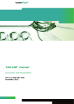
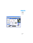
II. MPB 3200 front panel - overview
6
III. Operating instructions for radio, cable and
quartz-controlled construction site traffic
signal system Type MPB 3200
Alternating one-way traffic at construction sites between 50 and more than
1000 m long can be controlled with the vehicle-actuated traffic signal system
type MPB 3200.
Please proceed as follows to commission the system:
1.
Open the bottom chamber with green lens in both signal heads. This is
where the controllers are installed with the control elements and
information display. Set the rocker switch to "System off" for both signal
heads. All signal heads are 100% identical, so that you can choose for
yourself which signal head works as transmitter or receiver (with active
feedback). To do so, select one signal head as Transmitter (T) and adjust
this accordingly at the second knob from the top. Then adjust the second
signal head as Receiver (R).
2.
Provide both signal heads with operating voltage 12 V DC by connecting
batteries or power supply units type N1. Ensure that you do not confuse
the polarity (red is plus).
3.
Select the required transmission type with the "Radio/Quartz/Cable"
function switch in the same setting for both controllers.
4.
At both controllers, i.e. at the transmitter and receiver signal head, use the
knobs to adjust the "clearance time in seconds", e.g. using the interim
times table (page 4 of these instructions) or according to the phase plan
for the particular construction site.
5.
Important note:
The set clearance time for the transmitter controller (R -> T) starts to run
after the end of the green phase in the receiver controller, and the set
clearance time for the receiver controller (T -> R) starts to run after the end
of the green phase for the transmitter controller.
Adjusting the green phases for the transmitter and receiver in radio, cable or
quartz mode:
5.a. Automatic fixed time mode or automatic for quartz
Adjust the required green phase with the "Green phase in seconds"
knob on the transmitter and receiver controller.
7
Adjusting the green phases for the transmitter and receiver for the following
operating modes in radio or cable mode:
5.b. Automatic green phase extension and automatic request mode
Adjust the required maximum green phase with the "Green phase in
seconds" knob on the transmitter and receiver controller.
Explanation for vehicle-actuated radio or cable mode for automatic
green phase extension and automatic request mode:
a.
Minimum green phase
This is the phase which always runs even if there is no traffic. It has been
adjusted permanently in the factory to 10 seconds. In the automatic
request mode, the system remains in the all-red basic setting if there are
no vehicles present.
b.
Time gap (extension time)
The time gap (extension time) is used to extend the green phase after the
end of the internally fixed setting for the minimum green phase.
Depending on the volume of traffic, the green phase can be extended up
to the maximum green phase setting. If no more vehicles are registered
between the minimum and maximum green phase (within 6 seconds), the
current green phase is ended. The time gap has been adjusted
permanently in the factory to 6 seconds.
6.
Use the "Mode" knob to adjust the required mode for both controllers.
7.
Set the rocker switch to "System on" for both signal heads.
Both signal heads now briefly show the signal pattern "yellow flashing". They
then switch automatically to the switch-on program in the adjusted mode.
Note:
The clearance times and green phases for the transmitter and receiver can
also be adjusted while the system is operating! However, changes to the
clearance times and green phases for the transmitter or receiver which have
been adjusted in the radio or cable mode are only adopted after pressing the
button above the information display on one signal head for five seconds (the
information display shows a time progress bar).
Changes in quartz mode have to be made to each signal head. To this end,
please switch the traffic signal off first, and then resynchronise it again after
making the changes.
8
Resynchronising in quartz mode
In quartz mode, check the synchronisation of the traffic signal every day and
resynchronise if necessary (see IV, point 1.).
Aligning the radar detectors in vehicle-actuated mode
Always align the directional radar detector so that oncoming traffic is
registered correctly, because otherwise troublefree vehicle-activated
operation of the traffic signal cannot be warranted.
Correct alignment can be checked by using the red LED on the front of the
radar detectors on the one hand, and the illuminated LCD information display
on the front panels of every controller (display shows (+) during evaluation) on
the other hand.
Changing the batteries
For quartz mode: when changing the batteries, synchronisation is retained
for up to 15 minutes by an internal buffer battery; the signal head and the
information display switch off. After the new battery has been connected, the
system automatically switches back to the program.
For cable or radio mode: when changing the batteries, the signal heads and
information display switch off, the other side automatically changes to red for
one minute. After changing the battery, the signal head automatically changes
to all-red according to the switch-on pattern, then the system starts normal
operation again.
IV. Modes of MPB 3200
1. Automatic for quartz
Switch the mode switch for both controllers to setting 3-Automatic for
quartz. The times have already been adjusted as described above. The
signal heads still flash. You can now synchronise the traffic signal. To do so,
press the button on the first signal head and the program starts to run. At
the
second signal head, press the button exactly when the first signal
head
changes from green to yellow. In this mode, the previously
adjusted green phases run according to the fixed setting, regardless of the
volume of
traffic. The traffic signal automatically performs the
clearance time on the
basis of the previously adjusted clearance times for
transmitter and
receiver.
Factory time settings:
red/yellow phase: 1 second
yellow phase:
4 seconds
(in the German MPB 3200 version, otherwise according to the corresponding national regulations)
9
2. Continuous green/continuous red for quartz
(manual operation for quartz)
The manual operation settings are adjusted at the corresponding signal head.
Now set the mode switch for the corresponding controller to setting 1Continuous green for quartz. The signal head now switches from the
automatic program to continuous green and remains in this signal pattern
until another mode is selected. Please note that the other signal head
should already have been set to continuous red for quartz mode setting 2.
Manual operation is now possible by switching between the modes 1Continuous green and 2-Continuous red; it is also possible to block the
traffic flow completely by remaining in the setting 2-Continuous red.
3. Lamps off
Set the mode switch to setting 4-Lamps off at both controllers for quartz
mode and at one controller for radio or cable mode. The lamps are switched
off, the controller continues to run. In radio or cable mode, at the end of this
current cycle the traffic signal switches to Lamps off with the switch-off
pattern. To return to automatic mode, simply set the mode switch back to
the required automatic setting. After a few seconds, the traffic signal
switches back to the required program.
4. Flashing
Set the mode switch to setting 5-Flashing at both controllers for quartz
mode and at one controller for radio or cable mode. The system switches to
yellow flashing, the controller continues to run. In radio or cable mode, the
traffic signal only switches to flashing at the end of this current cycle. To
return to automatic mode, simply set the mode switch back to the required
automatic setting. After a few seconds, the traffic signal switches back to
the required program.
5. Automatic fixed time mode
Set the mode switch to setting 6-Automatic fixed time mode at the
controller selected as transmitter. This mode operates with the previously
adjusted green phases, regardless of the volume of traffic. In this mode, the
previously adjusted green phases run according to the fixed setting
regardless of the volume of traffic. The traffic signal automatically performs
the clearance time on the basis of the previously adjusted clearance times
for transmitter and receiver.
Factory time settings:
red/yellow phase: 1 second
yellow phase:
4 seconds
(in the German MPB 3200 version, otherwise according to the corresponding national regulations)
10
6. Automatic green phase extension
Set the mode switch to setting 7-Automatic green phase extension at the
controller selected as transmitter. In this mode, the previously adjusted
green phases run as maximum green phase, depending on the volume of
traffic. The minimum green phase permanently adjusted in the factory is 10
seconds.
This minimum green phase always runs, regardless of vehicle traffic. The
directional radar detectors register all oncoming vehicles and thus adjust
the minimum green phase automatically to the volume of traffic, extending
it up to the maximum green phase if necessary. The extension time for each
radar detection, the so-called time gap, has been adjusted to 6 seconds in
the factory.
7. Automatic request mode
Set the mode switch to setting 8-Automatic request mode at the controller
selected as transmitter. In this mode, the previously adjusted green phases
run as maximum green phase, depending on the volume of traffic. The
minimum green phase permanently adjusted in the factory is 10 seconds.
This minimum green phase always runs, regardless of vehicle traffic, but it
can be extended up to the maximum green phase, depending on the
volume of traffic. The extension time for each radar detection, the so-called
time gap, has been adjusted to 6 seconds in the factory. In contrast to
setting 7-Automatic green phase extension, in mode 8 the system remains
set to continuous red until a vehicle is registered by a radar detector. The
signal head which has registered a vehicle now changes to green after the
clearance time has expired. When there is an increase in the volume of
traffic, the green phase is extended as described above. At the latest after
the end of the maximum green phase, the signal head switches back to red
and the traffic signal remains set to continuous red until the next vehicle is
registered.
Note: in this mode with all-red basic setting, a compulsory cycle with a
trigger time of 5 min has been permanently adjusted in the factory (can be
changed on the PCB using the DIP switches). That means that the traffic
signal still changes to green at least every 5 minutes, if the radar detectors
are incorrectly adjusted or defect. This prevents traffic coming to a
complete standstill.
Factory time settings:
red/yellow phase:
1 Sekunde
yellow phase:
4 Sekunden
(in the German MPB 3200 version, otherwise according to the corresponding national regulations)
min. green phase: 10 Sekunden
time gap:
6 Sekunden
11
The settings described below for manual mode in radio or cable mode
(switch settings 9, 10 and 11) are only adjusted at one signal head.
8. All-red for radio/cable
Now set the mode switch at one controller to setting 9-All red for
radio/cable. The traffic signal now switches from the automatic program to
continuous red. The traffic signal remains in this signal pattern until it is set
to another mode.
9. Green transmitter for radio/cable
Set the mode switch at one controller to setting 10-Green transmitter for
radio/cable. The traffic signal now switches from the automatic program
(while observing the clearance times) to continuous green at the
transmitter signal head. The traffic signal remains in this signal pattern until
another mode is selected.
10.Green receiver for radio/cable
Set the mode switch at one controller to setting 11-Green receiver for
radio/cable. The traffic signal now switches from the automatic program
(while observing the clearance times) to continuous green at the receiver
signal head. The traffic signal remains in this signal pattern until another
mode is selected.
Important note:
Modes 6-Automatic fixed time mode, 7-Automatic green phase extension and
8-Automatic request mode can only be selected from the controller which has
been defined as transmitter. But for better clarity, they should be adjusted to
the same setting in both controllers in normal mode.
The modes 4-Lamps off, 5-Flashing and 9-All red for radio/cable, 10-Green
transmitter for radio/cable and 11-Green receiver for radio/cable can be
adjusted at any signal head.
12
V. Explaining the information in the display
Battery voltage or other information
only for VA mode:
+ = message
= request saved
Traffic light configuration and signal pattern
12,8 V Light T
Red 10s
Lamp status
Cycle seconds
1.
General information
When the system is switched on, it proceeds with an internal self-check
and announces itself as Peter Berghaus Traffic Signal System MPB
3200; the software status is displayed. Then the current operating
voltage is shown in plain text. The display lighting is now switched on for
10 minutes. During on-going operation, you can also switch the display
lighting on for 10 minutes by pressing the "Light / Display" button to the
right of the display; press this button several times to see the status
information.
2.
Information during on-going operation
After adjusting the mode, first the status of the connection is shown,
followed by the selected mode as abbreviation, e.g. "AUTO", alternating
with the operating voltage. Similarly, the display states whether the user
has selected this signal head as transmitter "T" or receiver "R".
In radio mode, after pressing the "Light / Display" button, the display
shows among others the reception field strength as a bar diagram. Press
the button again to see the function of the "LDR" light sensor respectively
brightness as a percentage together with the connection quality "GOOD /
act." The status of the signal head is shown in diagrams in the display.
For example, means red, yellow and green. Similarly, this status
is also shown in plain text and with a decreasing second time bar. In
manual mode for radio or cable, two traffic light symbols are shown for
better clarity, so that the operator also sees information about the status
of the other side.
13
3.
Function display of the radar detector
(only for the "VA active" version)
In vehicle-actuated mode, the display shows the symbol “+” or “(+)”.
on the left. The radar detector has registered an oncoming vehicle,
triggering a request to the controller which is now processed. The road
user can see this when the red LED in the radar detector lights up briefly.
4.
Display of defects
• “Red defect T/R” -> red bulb defect in transmitter/receiver
• “Yellow defect T/R” -> as above but yellow bulb defect
• “Green defect T/R” -> as above, but green bulb defect
Both signal heads only flash yellow when the red lamp is defect.
Otherwise the display only contains the text information stated above.
Now replace the defect bulb in the transmitter (T) or receiver (R) and
quit the fault by pressing the button above the display. After the red
defect has been remedied, the traffic signal starts up again
automatically.
• “No Rec.Light T/R” -> transmission fault
Both signal heads flash yellow, the displays show the text information
stated above. A fault has occurred in transmitting the data to the
transmitter or receiver. In cable mode, please check the connecting
cables and the plug-in connections. In radio mode, please first check
whether the frequency has been set to the same setting for both signal
heads (is only relevant for multi-frequency version). If the setting is
correct, please check the antennas and the plug-in connections at the
radio modules. After the fault has been remedied, the traffic signal
starts up again automatically.
• “Status green T/R” -> nom/act. comparison of control command and
signal pattern status
• “E.gr.grp T/R” -> green blocked (prevents both signal heads from
showing green at the same time, this is not allowed)
Both signal heads flash yellow, the displays show the text information
stated above. The traffic signal has sent an incorrect signal pattern.
Green/green monitoring prevents both signal heads from actually
showing green at the same time. Check the equipment visually for any
signs of damage to the cases and any moisture. Quit the fault by
pressing the button above the display at the displayed controller (T or
R). If the fault occurs again, send the traffic signal to the factory to be
checked.
14
VI. Special feature for export
(emergency quartz mode)
For the export version, on request an automatic changeover can be
activated between radio or cable and quartz mode (emergency quartz
mode).
What does emergency quartz mode mean?
When an existing radio or cable transmission breaks down, when the
emergency quartz function is activated in both controllers, the system
automatically changes over to synchronised emergency quartz mode. And so
the system continues to operate without any noticeable interruptions for
vehicle traffic.
The following clearance times and green phases are observed:
• The adjusted clearance times are extended by a further 5 seconds at
both signal heads (T + R).
• If you have adjusted green phases lasting up to 40 seconds, in the
emergency quartz mode these are restricted to a fixed 25 seconds.
• If green phases have been adjusted for longer than 40 seconds, these
are fixed internally to 45 seconds.
During the emergency quartz mode, in the background the traffic signal
system constantly tries to restore the radio or cable connection, and switches
back automatically to the previously adjusted mode when conditions for good
transmission have been restored.
Note:
After being turned into the export version, when there is a radio or
cable malfunction the traffic signal system then corresponds to type
class A "Bottleneck traffic signal system without signal safety
feature" (valid only in Germany).
Important note:
If the system is operating in the emergency quartz
mode, no data backup takes place on changing the
battery. Please start the traffic signal again in the
required mode after changing the battery .
15
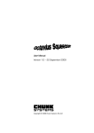
The traffic signal is changed over to the export version as follows:
Remove the front panels from both controllers, as described in chapter IX of
these operating instructions.
On the control PCBs of transmitter and receiver, jumper "JP 3" (see marked
section below) must be plugged into the other slot. In the factory setting,
the jumper connects the left contact with the middle contact: this
deactivates the emergency quartz mode (as per TL-LSA).
You can activate the automatic changeover between radio/cable and quartz
mode by connecting jumper "JP3" so that it connects the middle contact
with the right contact (Export).
Please note that this change has to be made to both control PCBs.
Then put the PCBs back as described in chapter IX. After switching on, the
display shows “Emergency quartz mode enabled”. This function is
permanently activated until jumper "JP3" is put back again.
16
VII. External cable hand-held control (accessory)
Commissioning and operation
1.
Note:
Before plugging in the external cable hand-held control which is
available separately as an accessory, first adjust the required mode on
the hand-held control using the knob. The hand-held control takes
priority so that the traffic signal immediately adopts the hand-held
control setting as soon as this is plugged in.
There is no need for any adjustments to the two signal head
controllers: the hand-held control is automatically detected as soon as
it is plugged in!
2.
Connect the external hand-held control to the socket on the prepared
controller. The corresponding socket (accessory ) is below the green
chamber.
3.
The traffic signal now changes over from the automatic program (while
observing the green phases) to the mode selected in the hand-held
control.
4.
The other modes are described in chapter IV of these operating
instructions.
5.
When the external hand-held control is disconnected from the socket,
the traffic signal automatically changes back to the mode originally set
in the controller.
6.
Close the socket for the external hand-held control again with the
fastened covering cap!
17
VIII. Bus priority – local public transport
(accessory)
Description
In some applications, it can be appropriate for the bottleneck traffic control to
give priority to local public transport. To this end, MPB 3200 can be modified
with the installation of the local public transport jack available as an accessory
so that it offers a potential-free contact, for example for connection a key
switch for the transport company or the radio remote control unit, also
available as accessory. Similarly, other detectors can be connected to the
local public transport jack to give priority to buses.
Function
An oncoming bus is registered by the corresponding signal head as
described above. The bus request now limits the green phase for the other
side to the minimum green phase of 10 seconds. At the end of the adjusted
clearance time, the bus on the requesting side sees green immediately up
to the maximum period. If during this green phase a request should come
from another bus from the same direction, the maximum green phase is
specified.
A request from the other side during this period is saved and then runs
subsequently.
If there are no other bus requests, the traffic signal continues to run in the
adjusted vehicle-actuated mode until the next request is received.
Note:
Bus priority is possible in modes 7-Automatic request mode and
8-All-red for radio/cable.
18
IX. Instructions for removing and fitting the
controller PCB
The following tools are required for removing and fitting the controller PCB:
•
•
•
•
5,5 mm socket wrench
8 mm socket wrench
medium Philips screwdriver
medium slotted screwdriver
A. Removing the controller PCB
1. Carefully lever out the caps on the knobs, for example with your
fingernails. You can now see a Philips screw. After you have loosened
these screws, all knobs can be pulled off to the front.
2. Use the 8 mm socket wrench to carefully unscrew the two rocker
switches.
3. Now you can pull the front panel off to the front.
4. You can now see the controller PCB. At about 3 cm from the corners
towards the middle, you can see 4 setscrews with nuts. Use the
5.5 mm socket wrench to loosen the setscrews so that you can take
the PCB out of the controller.
5. Now disconnect the connectors for the cable harness at the top and
for the buffer battery at the bottom. You are now holding the control
PCB.
B. Fitting the controller PCB
1. Restore the electrical connections between the cable harness and
the control PCB: do not forget to connect up the light-sensitive sensor
(LDR) for automatic adjustment to ambient brightness, as well as the
buffer battery. Now fasten the controller PCB on the four studs in the
green chamber. Then position the front panel over the controller. Put
the knobs on their shafts and fasten initially by tightening the screws
slightly. Then adjust to the smallest scale values.
19
2. Provide operating voltage 12 V DC by connecting batteries or power
supply units type N1. Ensure that you do not confuse the polarity.
3. Now press and hold both buttons: at the same time, switch the signal
head on with the rocker switch. First you see the message "Menu 1 Dswitch settings" and the display shows a separate symbol for each
knob, e.g.:
1
2
3
4
5
6
X
X
X
X
X
X
4. Counting anti-clockwise, we start with the frequency selection
switch (1), followed by the tens (2) and digits switch (3) for the
clearance time, then the green phase selection switch (4) and the
transmitter/receiver selection switch (5). The mode switch (6) comes
last.
To adjust the knobs to the lowest scale value, please watch the
display while turning for example frequency selection switch (1). As
soon as the display under switch 1 shows a 1 instead of an X, you
have reached the lowest value. Now you can align the scale arrow
to 1 and screw the frequency selection switch to its shaft. Then set the
cover cap on the screw head.
5. Proceed in the same way with the other knobs (2 to 6).
In the end, the display should look like this:
1
2
3
4
5
6
1
0
0
15
T
1
6. Now press the "Light / Display" button to change to the service point
"Menu 2 Additional setting 1". Here you can check that the LDR has
been connected correctly and is functioning. To do so, briefly cover
the light-sensitive sensor on the back of the green chamber with your
hand. The previously displayed value must now decrease clearly.
7. Press the "Light / Display" button again to change to the service point
"Menu 3 Additional setting 2". Here you can test the optional
additional inputs for local public transport activation (B) and the SMS
module (S) (if these optional items are present).
8. Press the "Light / Display" button one more time. You have left the
service menu; the traffic signal is now ready and can be programmed
for use.
20
X. Technical data
Operating voltage:
approx. 8 - 14 V DC
Power consumption in cable and quartz mode:
Daytime operation:
Daytime operation:
approx. 1.14 A per signal head (halogen)
approx. 0.52 A per signal head (LED)
Nighttime operation:
Nighttime operation:
approx. 0.78 A per signal head (halogen)
approx. 0.45 A per signal head (LED)
Power consumption in radio mode:
Daytime operation:
Daytime operation:
approx. 1.35 A per signal head (halogen)
approx. 0.75 A per signal head (LED)
Nighttime operation:
Nighttime operation:
approx. 0.98 A per signal head (halogen)
approx. 0.65 A per signal head (LED)
Lamps:
12 V/10 W halogen bulbs (commercially available)
or optimised low-energy LED modules on request
Fuse:
4A, 5x20, medium-slow fuse (commercially available)
Control modes:
fixed-time, vehicle-actuated with green-phase
extension, vehicle-actuated operation with green on
request, all-red, manual mode, flashing, lamps off
Data transmission:
cable or digital radio path
Radio path:
max. length under ideal conditions approx. 2,000 m
Radio equipment:
radio module,
tested in 1-channel, 3channel and 16-channel version.
Licensed 2m band frequencies for Germany:
151.09 MHz, 170.77 MHz, 170.75 MHz, 170.63 MHz
Transmitter output rating £ 100 mW
Other frequency ranges and frequencies are possible together for example
with higher transmitter output ratings according to the customer's national
regulations.
21
Annex 1: Radar detector (option)
Description of functions: radar movement detector
The movement detector mounted on this traffic light system MPB 3200
("VA" for vehicle-actuated option) is a directional radar detector specially
optimised for use in mobile signal systems.
The pivoting fixture on top of the traffic light signal head lets the radar detector
be aligned ideally to the approaching traffic. A clearly visible red LED in the
front of the radar detector shows the road user that his vehicle has been
detected.
Movements are detected according to the Doppler principle. The sensor emits
microwaves in the range of 24 GHz. These are reflected by objects moving
towards the sensor, so that their frequency is changed. The sensor receives
the changed frequencies with its planar microwave antenna and evaluates
them accordingly. Approaching movements within the detection field are
registered, evaluated reliably by the internal logic and forwarded to the traffic
light controller.
Compared to conventional infrared detectors, one major advantage of these
radar movement detectors specially optimised for mobile traffic light systems
is that they are capable of distinguishing between an object coming towards or
moving away from the radar detector. For example, only directional radar
detectors are capable of implementing a reliable continuous red phase or
green on request, when the approaching vehicle requests his own "green"
from the traffic light.
Simple infrared movement detectors would also register traffic moving away
from the traffic light – resulting in incorrect requests. Continuous red phases or
green on request cannot be implemented with infrared detectors.
In addition, the radar detector also differentiates between people and
vehicles. Furthermore, as a rule the detection range of a radar detector is not
impaired by snow or rain.
Applications:
Mobile traffic light systems; reliable detection for traffic technology
22
Special features:
l
Radar detection, insensitive to snow or rain
l
Precise directional logic optimised to approaching vehicles
l
Clear LED display on the detector shows when a vehicle has been
detected
l
Swivelling metal fixture for alignment exactly to the traffic flow
l
Radar detector hinged for protection during transport
l
Compact, weatherproof plastic housing
Technical data: radar detector
l
l
l
l
l
l
l
l
l
l
l
Housing dimensions (W x H x D): 135x65x130 mm
Material: ASA, PC plastic housing; steel holder
Protection: IP65 for use outside
Supply voltage: 12-27 VAC, 50-60 Hz; 12-30 VDC
Power consumption: typical 1 W, max. 2.4 W
Tolerable operating temperature: -20°C to +55°C
Storage temperature: -30°C to +75°C
Humidity: <95%, non-condensing
Frequency: 24.125 GHz
Transmission output: typical 40 mW EIRP; max. 100 mW EIRP
Maximum mounting height: 7 m
23
Spare Parts List
Article:
T raffic signal system M PB 3200
Order no.
Article description
S ignal head, type "Holland", 3-part, 210 mm, with lens hoods,
completely wired, incl. battery cable, reflectors, equipped with G4
MP B 3000
bulb holders and halogen lamps 12 V /10 W /G4, with connector
prepared for MP B 3200 controller
MP B 309 S ignal head rear panel for red chamber MP B 3200, 210 mm
MP B 308 S ignal head rear panel for yellow chamber MP B 3200, 210 mm
MP B 307 Green chamber/controller rear panel for MP B 3200, 210 mm
E H 2014 Gasket for signal head chambers, "Holland" type
E H 2016 S ignal head door without lens, "Holland type", 210 mm
E H 2017 S ignal head door, type "Holland", with red lens, 210 mm
E H 2018 S ignal head door, type "Holland", with yellow lens, 210 mm
S ignal head / controller door, type "Holland", with green lens,
MP B 304
210 mm, with lock no. 641
E H 2012 Lock for controller door no. 641, incl. one key
E H 2641 K ey no. 641
E H 2009 C loser for signal head door
E H 2008 C loser counterpart for chamber
E H 2020 Lens, red, type "Holland", 210 mm
E H 2021 Lens, yellow, type "Holland", 210 mm
E H 2022 Lens, green, type "Holland", 210 mm
E H 2034 Lens holder
E H 2023 Gasket for lens 210 mm, type "Holland"
E H 2030 Lens hood, type "Holland", 210 mm
E H 2031 C over cap for signal head, type "Holland"
E H 2032 Gasket for cover cap, self-adhesive, type "Holland"
Intermediate ring for connecting signal head rear panels, type
E H 2033
"Holland"
E G 0041 Halogen lamp 12 V /10 W /G4
E G 0084 Halogen G4 bulb holder
E H 2040
Reflector for G4 bulb holder, type "Holland" 210 mm for MP B 3200
E H 2100
LE D signal head module RE D for MP B 3200 as replacement
E H 2110
LE D signal head module YE LLOW for MP B 3200 as replacement
E H 2120
E S 3097
E S 3098
E K 0001
E I 0041
E I 0042
LE D signal head module GRE E N for MP B 3200 as replacement
S ocket plug, 3-pin, for LE D module system
P lug, 3-pin, for LE D module system
B attery cable for MP B 3200 with ring eylet, without battery lug
B attery terminal (+), red
B attery terminal (-), green
24
Order no.
Article description
MPB 313
MPB 110
ES 2031
ES 2004
Es2041
ESP 530
ESP 087
EF 0009
EF 1009
MPB 321
Front plate MPB 3200 with imprint
Rotary toggle for switch with arrow disk and cap
Safety cap for fuse (5 x 20)
Fuse 5x20 / 4 A
Dimmer swtich with cable and threaded joint
Controller PCB for MPB 3200
Battery PCB 7.2V MPB 3200 with cable and connector
Radio module, type FM-D 92 for MPB 3200
Radio module, type FM-D 92 for MPB 3200, in exchange
Cable harness, 9-wire for actuating lamps MPB 3200
Cable harness for radio system, complete, with 9-pin sub-plug and
11-pin PCB connector MPB 3200
Cable harness for data bus, complete, with 4-pin connector for PCB
MPB 3200
Radar detector 12 V incl. 0.5 m cable with mounted plug, without
mounting bracket
Mounting bracket for radio antenna and radar detector
Mounting bracket for radar detector in a cable system
Antenna radiator, type "Kathrein"
Antenna base, type "Kathrein"
Antenna radiator and base, type "Kathrein"
Antenna cable without plug, type "Kathrein"
Antenna plug, BNC (adapter), type "Kathrein"
Sub-plug 9-pin, for radio system, MPB 3200
Flange coupling 4-pin, ballast
Angled plug 4-pin, ballast
Flange coupling 7-pin, ballast
Flange plug 7-pin, ballast
Angled pin, 7-pin, ballast
Angled coupling, 7-pin, ballast
Cover cap for plug and flange plug, ballast
Cover cap for coupling and flange coupling, ballast
Battery casing made of aluminium for 2 batteries
Battery casing made of steel for 4 batteries
Castor, solid rubber
Cover cap for castor
Mounting tube, galvanised, for MPB 3000 / MPB 4000
Cover cap for mounting tube
Wing screw M 10x30
Electronic switching system for 2 batteries
Electronic switching system for 4 batteries
MPB 324
MPB 325
EP 6037
MP4008
MP400H
EFK 010
EFK 008
EFK 001
EFK 007
EFK 006
ES 3005
ES 3022
ES 3024
ES 3033
ES 3032
ES 3034
ES 3035
ES 3040
ES 3041
A 49600
A 50000
EE 0006
EE 0003
EE 0012
EE 0014
EE 0005
A 46500
A 46501
25
26
Warranty for defects
We offer a
24 month guarantee
for the signal systems produced by our company.
The guarantee covers all material and workmanship faults caused by faulty
manufacture during this period of time.
Please send systems and parts of systems for replacement to our factory,
postage/freight prepaid. We only replace parts showing faults in the material
or workmanship. There are no claims to rescission or abatement, unless we
are not able to rectify the damage.
No further claims can be fulfilled, in particular claims for damages as a
consequence of defects.
The necessary time and opportunity to proceed with guarantee repairs must
be made available following previous agreement. The guarantee becomes
null and void if the customer or third parties make changes or repairs without
prior consent. The guarantee does not cover any wear or damage caused by
negligent or incorrect handling.
If in exceptional cases at the customer's request warranty repairs are to be
carried out on site, i.e. at the road works where the system causing the
complaint has been installed, the service technician's travel expenses and
journey times are not covered by the warranty and shall be invoiced
separately to the client.
The place of jurisdiction for all claims arising from the business relationship is
Bergisch Gladbach, Germany.
General transport instructions for mobile traffic signal
systems
Please note!
Our construction site traffic signal systems must always be transported
standing upright on open vehicles with the lens hood pointing in the opposite
direction.
To prevent any water damage, all signal head chambers and the controller
housing must always be closed properly and the controller housing should
also be locked!
Failure to comply with these instructions automatically renders the warranty
null and void!
27
Peter Berghaus GmbH
Traffic Technology • Mobile Crash Barriers
28
Peter Berghaus GmbH
Traffic Technology • Mobile Crash Barriers
29
Peter Berghaus GmbH
Traffic Technology • Mobile Crash Barriers
30
Traffic Technology • Mobile Crash Barriers
Herrenhoehe 6 • D-51515 Kuerten • phone +49 2207 96770 • fax +49 2207 967780
www.berghaus-verkehrstechnik.de • [email protected]
05/2010
Peter Berghaus GmbH