1
Current Electrode Potential Recording
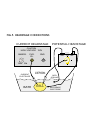
In order to determine whether both electrodes are inserted into the same cell, the potential of
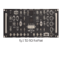
the current injecting microelectrode (CEL, see 2.2) is recorded by a buffer amplifier in the
current headstage with a x10 mV scaling (Cel. POTENTIAL x10 mV BNC). This unit is
equipped with an offset compensation (CEL. OFFSET, ten-turn potentiometer,. +/- 500 mV).
WARNING: Due to the limited operation range of the output amplifier (±12 V maximum)
the high voltage signals occurring during current injection will drive this output into
saturation (clipping). Therefore during electrode positioning no current flow should occur
through the current electrode (CEL). During voltage clamp mode the signals at this output may
become very noisy.
WARNING: The CEL Offset control is symmetrical (operating both in positive and negative
direction), therefore setting to zero occurs on position 5.00 on the dial. 10 is maximum in
positive direction 0 is maximum value on negative direction
Potential Monitor and Audio Monitor
The measured membrane potential is amplified, PEL by a factor of 10 or 40, CEL by a factor of
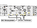
ten. The recorded potentials from both microelectrodes (PEL and CEL) can be read out from the
respective BNC-sockets (POTENTIAL OUTPUT PEL x10 or PEL x40, and CEL x10), and can
also be directly (not amplified) displayed in mV on a digital display. The electrode which is
monitored at the display is selected by a toggle switch located at the left side of the display
(POTENTIAL ELECTRODE or CURRENT ELECTRODE).
In addition the recorded potentials are converted to a sound with a potential dependent pitch
with the AUDIO MONITOR. The electrode which is monitored by the AUDIO MONITOR is
also selected by toggle switch POTENTIAL ELECTRODE or CURRENT ELECTRODE.
2.2 CURRENT INJECTION AND CURRENT MEASUREMENT
Current Injection
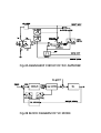
The current injection is performed by means of a glass microelectrode which is connected to
the current headstage (CEL). A description of the current headstage is given in chapter 3.2.
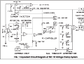
The unique advantage of the instruments in the Turbo TEC series is the voltage-controlled
current source output (V/C or V/I converter), for electrical compensation of the disturbances
from the microelectrode during current injection (i.e. high resistance and stray capacity, see
Polder, 1984, Polder & Swandulla, 1990). This current source is built into the current
headstage. Due to this current source output, current injection becomes independent from the
resistance of the microelectrode which is usually strongly nonlinear. In addition, this circuit
allows direct measurement of the current injected in the cell without the necessity of a virtual
ground circuit for the bath.
Output Current Zero (C. HEADSTAGE BIAS CURRENT)
In order to adjust the zero-current of the output current source, each instrument provides a
bias current adjustment with a 10-turn potentiometer (ca. +/- 0.5% of the current range). The
tuning procedure is described in the INSTALLATION chapter.
8