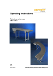
1
â
FÖRDERSYSTEME - CONVEYING SYSTEMS - SYSTÈMES CONVOYEURS
Operating Manual
for the models
AM-Z-W
AM-R
Must be read
before
initial use !!!
AM-K
GEPPERT-Band GmbH
Karl-Heinz-Beckurts-Str. 7
D-52428 Jülich
Also applies to:
AM-RW
AM-KW
AM-Z
AM-S
Phone:
Fax:
+49 2461 93767 0
+49 2461 93767 30
Email:
Website:
[email protected]
www.geppert-band.de
â
AM-F operating manual
FÖRDERSYSTEME - CONVEYING SYSTEMS - SYSTÈMES CONVOYEURS
Table of contents:
1
2
Foreword .......................................................................................................................................... 4
Safety when handling our belt conveyors ........................................................................................ 4
2.1
Safety equipment on our belt conveyors .................................................................................. 4
2.2
General instructions on the proper operation of belt conveyors ............................................... 4
2.3
Obligations of the company operating the belt conveyor .......................................................... 5
2.4
Safety symbols .......................................................................................................................... 5
3 Dimensions and Data ....................................................................................................................... 6
3.1
Belt conveyor frame .................................................................................................................. 6
3.2
Plastic module chains ............................................................................................................... 9
3.3
Motors ..................................................................................................................................... 10
3.3.1
Geared motor type SN3F:................................................................................................ 10
3.3.2
Geared motor type SN9F:................................................................................................ 11
3.3.3
Geared motor type SN8F:................................................................................................ 12
3.4
Electrical devices .................................................................................................................... 13
3.4.1
Frequency converter ........................................................................................................ 13
3.4.2
Protective motor switch .................................................................................................... 14
3.4.3
Emergency stop switch .................................................................................................... 15
4 Adjustments .................................................................................................................................... 16
4.1
Drive units ............................................................................................................................... 16
4.1.1
Drive unit underneath the belt.......................................................................................... 16
4.1.2
Lateral drive unit .............................................................................................................. 18
4.2
Adjusting the Conveyor Chain ................................................................................................ 20
4.2.1
Adjusting the tension of the conveyor chain .................................................................... 20
4.2.2
Adjust the length of the conveyor chain ........................................................................... 20
4.2.3
Direction of movement of the conveyor chain ................................................................. 21
4.3
Support .................................................................................................................................... 22
4.3.1
Protection against tilting of flat belt conveyors ................................................................ 22
4.3.2
Two-legged aluminium support........................................................................................ 23
4.3.3
Short two-legged aluminium support ............................................................................... 24
4.3.4
Two-legged steel support ................................................................................................ 24
4.3.5
Short two-legged steel support ........................................................................................ 25
4.3.6
Short steel support with lateral retainer ........................................................................... 25
4.3.7
Two-legged stainless steel support ................................................................................. 25
4.3.8
Single-legged support made of steel with aluminium base plate .................................... 26
4.3.9
H single-legged support made of steel ............................................................................ 26
4.3.10 H single-legged support made of steel, movable on castors ........................................... 27
4.3.11 H single-legged support made of stainless steel ............................................................. 27
4.3.12 H single-legged support made of stainless steel, movable on castors............................ 27
4.4
Flexible belt conveyors ........................................................................................................... 28
5 Spare parts ..................................................................................................................................... 29
as of June 2014
Page 2 of 29
â
AM-F operating manual
FÖRDERSYSTEME - CONVEYING SYSTEMS - SYSTÈMES CONVOYEURS
List of illustrations:
Figure 3-1:
Figure 3-2:
Figure 3-3:
Figure 3-4:
Figure 3-5:
Figure 3-6:
Figure 3-7:
Figure 3-8:
Figure 3-9:
Figure 3-10:
Figure 3-11:
Figure 3-12:
Figure 3-13:
Figure 4-1:
Figure 4-2:
Figure 4-3:
Figure 4-4:
Figure 4-5:
Figure 4-6:
Figure 4-7:
Figure 4-8:
Figure 4-9:
Figure 4-10:
Figure 4-11:
Figure 4-12:
Figure 4-13:
Figure 4-14:
Figure 4-15:
Figure 4-16:
Figure 4-17:
Figure 4-18:
Figure 4-19:
Figure 4-20:
Figure 4-21:
AM-F frame dimensions ..................................................................................................... 6
AM-C frame dimensions ..................................................................................................... 6
AM-R frame dimensions ..................................................................................................... 7
AM-K frame dimensions ..................................................................................................... 7
AM-Z-W frame dimensions ................................................................................................ 8
Table of the plastic module chains ..................................................................................... 9
Frequency converter ........................................................................................................ 13
Frequency converter connection to the motor ................................................................. 13
Protective motor switch .................................................................................................... 14
Protective motor switch connection to the motor ............................................................. 14
Emergency stop switch .................................................................................................... 15
Emergency stop switch connected to 230V 50Hz............................................................ 15
Emergency stop switch connected to 380V 50Hz............................................................ 15
Dismantling the chain cover ............................................................................................. 16
Adjusting the slack of the chain........................................................................................ 16
Chain slack target value ................................................................................................... 17
Dismantling the engine at the side ................................................................................... 18
Adjusting the play of the coupling .................................................................................... 18
Rotation of the motor ........................................................................................................ 19
Adjusting the slack of the conveyor chain ........................................................................ 20
Opening and closing the conveyor chain ......................................................................... 20
Direction of movement of the conveyor chain .................................................................. 21
Maximum weight at the end of the belt with mobile supports .......................................... 22
Two-legged support made of aluminium, height adjustment ........................................... 23
Two-legged support made of aluminium, inclination adjustment ..................................... 23
Two-legged steel support, height adjustment .................................................................. 24
Two-legged steel support, inclination adjustment ............................................................ 24
Short steel support with lateral retainer, height adjustment ............................................. 25
Single-legged support made of steel with aluminium base plate, height adjustment ...... 26
Single-legged support made of steel with aluminium base plate, inclination adjustment 26
H single-legged support made of steel, movable, brake .................................................. 27
Possible angles of bend ................................................................................................... 28
Setting the angle of bend ................................................................................................. 28
Adjusting the angle of the upper bend ............................................................................. 29
as of June 2014
Page 3 of 29
â
AM-F operating manual
FÖRDERSYSTEME - CONVEYING SYSTEMS - SYSTÈMES CONVOYEURS
1 Foreword
Our belt conveyors are intended for in-plant use; they are not suitable for wet rooms or operating areas
which are at risk of explosion. Special designs suitable for such areas, however, can be made available
after consultation and confirmation.
As the only maintenance measure required for the belt conveyors we recommend to occasionally check
the proper running of the belt. To adjust the running of the belt, we urgently advise you to comply with
the instructions given in this operating manual.
2 Safety when handling our belt conveyors
All of our standard belt conveyors were designed with a particular focus on safety. Especially when
working on the belt conveyors, unnecessary risks should be avoided. For this reason we have
deliberately designed many components such that the risk of injury for the operating personnel
operating our belt conveyors is minimised.
2.1
Safety equipment on our belt conveyors
One of the most frequent types of accident on belt conveyors is injuries to parts of the body which are
drawn in between the circulating belt and the rotating rollers. In order to make it impossible for such
accidents to occur or to reduce the risk as much as possible, all GEPPERT belt conveyors are fitted
with a gap protection at all points where the belt runs onto a cylinder or roller. This gap protection is
designed in such a way that during adjustment work it is automatically positioned in correct relation to
the roller.
To prevent damage to electrical equipment and minimise the risk of an electric shock, all of the parts of
our belt conveyors are earthed.
All belt conveyors are fitted with a safety switch as standard, which will automatically switch off the
device if it is overloaded or overheated. In addition, all devices have an emergency stop switch to turn
off the belt conveyor if there is imminent danger present. See also section 3.4.
If a belt conveyor is ordered without a safety switch or emergency stop switch, the operator must ensure
the correct connection of the device and the possibility of bringing it to a standstill in the case of danger.
2.2
General instructions on the proper operation of belt conveyors
All mechanical installation work may only be performed by industrial mechanics (industrial fitters) or
individuals who have received corresponding comparable training or instruction.
All work carried out on the electrical equipment may only be performed by trained electricians or
individuals who have undergone comparable training.
The operators and anyone working on a belt conveyor must wear appropriate protective clothing. This
includes in particular safety shoes for protecting against falling objects, as well as tight-fitting clothes
and hairnets for individuals with long hair to minimise the risk of their hair being drawn into the device.
The correct functioning of the emergency stop equipment should be checked every day. This also
includes a check of the protection against accidental restart after a drop in voltage. After a drop in
voltage, the device must not be able to start up again of its own accord. It may only start after a switch
has been activated.
If technically possible and provided for, the working height should be set to a level which is
ergonomically meaningful.
Touching the belt while it is running, as well as the transport of individuals on the conveyor, is not
permitted.
In an emergency, the belt conveyor can be moved backwards after being switched off by hand by
pulling on the belt.
as of June 2014
Page 4 of 29
â
AM-F operating manual
FÖRDERSYSTEME - CONVEYING SYSTEMS - SYSTÈMES CONVOYEURS
2.3
Obligations of the company operating the belt conveyor
The company operating a belt conveyor must ensure that the important preconditions for the safe
functioning of the device are fulfilled. For this, the following must be complied with:
-
2.4
The workplace of people working on the belt must be sufficiently illuminated.
The devices may only be used within buildings.
Compliance with the approved weights must be ensured. Here, attention must also be paid to the
danger of belt conveyors on supports with castors tipping over.
Any retrofitted parts must not result in the operator being placed at risk.
Safety symbols
Some of our standard belt conveyors may be furnished with special safety test symbols. Upon request,
these will also be attached to the device.
However, a specific adaptation is often required due to the individual use of the belt conveyor. This can
be carried out by us as the manufacturer or by the client himself. In both cases this may result in the
safety test symbol no longer being valid.
as of June 2014
Page 5 of 29
â
AM-F operating manual
FÖRDERSYSTEME - CONVEYING SYSTEMS - SYSTÈMES CONVOYEURS
3 Dimensions and Data
3.1
Belt conveyor frame
The most important dimensions of the AM-F / AM-C / AM-R / AM-K / AM-Z-W belt conveyors are shown
in the following illustrations:
Figure 3-1:
AM-F frame dimensions
Figure 3-2:
AM-C frame dimensions
as of June 2014
Page 6 of 29
â
AM-F operating manual
FÖRDERSYSTEME - CONVEYING SYSTEMS - SYSTÈMES CONVOYEURS
Figure 3-3:
Figure 3-4:
as of June 2014
AM-R frame dimensions
AM-K frame dimensions
Page 7 of 29
â
AM-F operating manual
FÖRDERSYSTEME - CONVEYING SYSTEMS - SYSTÈMES CONVOYEURS
Figure 3-5:
AM-Z-W frame dimensions
The frame dimensions of the AM-Z and the AM-S correspond to those of the AM-K and AM-R.
The frame dimensions of the AM-RW and the AM-KW correspond to those of the AM-Z-W.
as of June 2014
Page 8 of 29
â
AM-F operating manual
FÖRDERSYSTEME - CONVEYING SYSTEMS - SYSTÈMES CONVOYEURS
3.2
Plastic module chains
The technical data of the plastic module chains which are used most frequently by us is shown in the
following overview.
Chain types
Belt widths
QNB
ASB
S-MPB
153 mm
147 mm
228 mm
305 mm
301 mm
304 mm
457 mm
454 mm
380 mm
610 mm
607 mm
456 mm
532 mm
608 mm
Bolts
PA6.6
PA6.6
PA6.6
Division
25.4 mm
25.4 mm
25.4 mm
Overall thickness
8,8 mm
12 mm
8,8 mm
Colour
blue
blue
white
Material supporting
side
PP
POM-D
PP
smooth, closed
smooth, open 43%
smooth, closed
Antistatic
Non
Non
Non
Resistant to oil and
grease
Yes
Yes
Yes
Yes
+1°C to +104°C
Yes
- 40°C to + 90°C
Yes
+1°C to +104°C
Surface of the
supporting side
FDA approval
Temperature range
Figure 3-6:
as of June 2014
Table of the plastic module chains
Page 9 of 29
â
AM-F operating manual
FÖRDERSYSTEME - CONVEYING SYSTEMS - SYSTÈMES CONVOYEURS
3.3
Motors
Standard three-phase AC motors with worm gears with the protection rating IP 54 are used as standard
in our belt conveyors. The dimensions and data of the various standard motors are listed below. Special
motors are available on request.
The adjustment and maintenance of the drive chains or couplings are described in section 4.
3.3.1
c1
Geared motor type SN3F:
Mounting dimensions
ød1 ød2 ød3 ød4 j øs1
10 120 100 80
52
3
M6
g
g1
k
Outline dimensions
k1
o1
q1
o
q
125 108 288,5 187 41,5
33
99
35
y
z
ød
30
74
14
Shaft dimensions
l1
l2
l
t
30,0 20
Gearbox data
Motor data
180 Watt, 1400 rpm, weight 6,1Kg, 0,7Amps with 380V, IP54
Gearbox ratio
7:1
10 : 1
15 : 1
20 : 1
30 : 1
Gearbox speed
200 rpm
140 rpm
93 rpm
70 rpm
47 rpm
Effective torque
6,7 Nm
10 Nm
12 Nm
12 Nm
14 Nm
max. permissible torque
12 Nm
12 Nm
13 Nm
13 Nm
13 Nm
as of June 2014
5
16,0
u
5
56 : 1
25 rpm
17 Nm
10 Nm
Page 10 of 29
â
AM-F operating manual
FÖRDERSYSTEME - CONVEYING SYSTEMS - SYSTÈMES CONVOYEURS
3.3.2
Geared motor type SN9F:
c1
Mounting dimensions
ød1 ød2 ød3 ød4 j øs1
8
120 100 80
65
3
7
g
g1
k
Outline dimensions
k1
o1
q1
o
q
140 114 327 207 60
40 102 40
y
z
ød
i
25 121 16
1
Shaft dimensions
l1
l2
l
t
35
Gearbox data
Motor data
370 Watt, 1400 rpm, weight 9,2Kg, 1,2Amps with 380V, IP54
Gearbox ratio
7:1
10 : 1
15 : 1
20 : 1
30 : 1
Gearbox speed
207 rpm
140 rpm
93 rpm
70 rpm
47 rpm
Effective torque
14 Nm
20 Nm
27 Nm
29 Nm
36 Nm
max. permissible torque
30 Nm
30 Nm
28 Nm
29 Nm
30 Nm
as of June 2014
25
5
18
u
5
50 : 1
28 rpm
48 Nm
27 Nm
Page 11 of 29
â
AM-F operating manual
FÖRDERSYSTEME - CONVEYING SYSTEMS - SYSTÈMES CONVOYEURS
3.3.3
c1
Geared motor type SN8F:
Mounting dimensions
ød1 ød2 ød3 ød4 j øs1
10 120 100 80
80
3
7
g
g1
k
Outline dimensions
k1
o1
q1
o
q
140 114 334 207 67
53 124 46
y
z
ød
i
25 141 20
1
Shaft dimensions
l1
l2
l
t
50
Gearbox data
Motor data
550 Watt, 1400 rpm, weight 10,7Kg, 1,6Amps with 380V, IP54
Gearbox ratio
7:1
10 : 1
15 : 1
21 : 1
30 : 1
Gearbox speed
210 rpm
145 rpm
93 rpm
67 rpm
47 rpm
Effective torque
21 Nm
28 Nm
41 Nm
50 Nm
56 Nm
max. permissible torque
56 Nm
57 Nm
60 Nm
57 Nm
59 Nm
as of June 2014
30
10
22,5
u
6
50 : 1
28 rpm
60 Nm
51 Nm
Page 12 of 29
â
AM-F operating manual
FÖRDERSYSTEME - CONVEYING SYSTEMS - SYSTÈMES CONVOYEURS
3.4
Electrical devices
All of our electrical devices may only come into contact with dust and liquids as specified by the
protection rating applicable to them. Any contact of the electrical devices with liquids or dust that goes
beyond this must be avoided.
3.4.1 Frequency converter
All of our belt conveyors which are to have adjustable belt
speeds are equipped with a frequency converter as standard
which controls a robust three-phase AC motor.
For all motors up to 250 watts performance the GB-FU 250
device is used. For motors from 250 to 370 watts the GB-FU
370 device is used. Motors which have more power than 370
watts are fitted with a frequency converter that is specifically
adapted to them.
Figure 3-7:
Frequency converter
All frequency converters are digital devices which can be
individually programmed.
Each frequency converter also includes the function of
protecting the motor against overload. Thus the destruction
of the motor by a mechanically jammed belt conveyor is
almost impossible. In this case the frequency converter
turns the current off.
The frequency converters are connected to 230V 50Hz AC.
Separate operating instructions exist for these devices and
are enclosed with every delivery.
Any change to the programming may only be carried out by
trained personnel and after consultation with Geppert Band.
Figure 3-8:
Frequency converter
connection to the motor
Furthermore, the frequency converter is equipped with an emergency stop switch in the form of a
mushroom-type button to stop the belt conveyor quickly in the case of danger. After the voltage has
dropped, the belt conveyor does not restart automatically, but a separate start button has to be
operated.
as of June 2014
Page 13 of 29
â
AM-F operating manual
FÖRDERSYSTEME - CONVEYING SYSTEMS - SYSTÈMES CONVOYEURS
3.4.2 Protective motor switch
All of our belt conveyors which are to have a constant belt
speed are equipped with a protective motor switch, which
controls a sturdy three-phase AC motor.
Figure 3-9:
Protective motor switch
The protective motor switch has the function of protecting
the motor against overload. Thus the destruction of the
motor by a mechanically jammed belt conveyor is almost
impossible. In this case the protective motor switch turns the
current off. Furthermore, the protective motor switch is
equipped with an emergency stop switch in the form of a
snap-switch, which makes it possible to bring the belt
conveyor to a standstill quickly.
The protective motor switch is connected to 380V 50Hz
three-phase current.
Figure 3-10:
Protective motor switch
connection to the motor
as of June 2014
Page 14 of 29
â
AM-F operating manual
FÖRDERSYSTEME - CONVEYING SYSTEMS - SYSTÈMES CONVOYEURS
3.4.3 Emergency stop switch
In addition, all belt conveyors can be fitted with one or
more emergency stop switches in the form of a
mushroom-type button.
The emergency stop switch is positioned between the
source of the current and the belt conveyor in series,
so that individually operating any switch will
immediately bring the entire belt conveyor to a
standstill.
Figure 3-11:
Figure 3-12:
Emergency stop switch connected to 230V 50Hz
Figure 3-13:
Emergency stop switch connected to 380V 50Hz
as of June 2014
Emergency stop switch
Page 15 of 29
â
AM-F operating manual
FÖRDERSYSTEME - CONVEYING SYSTEMS - SYSTÈMES CONVOYEURS
4 Adjustments
During all adjustment work it must be ensured that all of the covers and brackets that have been
removed to carry out such work are correctly reattached after the adjustments have been carried out
and before the belt is put back into operation.
4.1
Drive units
4.1.1 Drive unit underneath the belt
If the drive unit is attached below the belt conveyor, it must be ensured that the drive chain is correctly
tensioned. The chain should be lightly greased.
In order to adjust the drive
chain, it is first necessary, as
shown in the adjacent
illustration, to remove the
chain cover (A) from the motor
support plate (B). For this
purpose, undo the fixing
screws (C).
Figure 4-1:
Dismantling the chain cover
Figure 4-2:
Adjusting the slack of the chain
Then the play of the chain (A)
can be adjusted, as shown in
the adjacent illustration. For
this purpose, undo the fixing
screws (B). Then the motor
(C) can be moved by turning
the adjustment screw (D).
as of June 2014
Page 16 of 29
â
AM-F operating manual
FÖRDERSYSTEME - CONVEYING SYSTEMS - SYSTÈMES CONVOYEURS
The play of the chain (A)
should, as shown in the
adjacent illustration, be
approximately 3-5mm. After
the tension in the chain (A)
has been adjusted, firmly
retighten the fixing screws (B).
Then check again whether the
play of the chain (A) is within
the envisaged range.
3-5 mm
Figure 4-3:
as of June 2014
Chain slack target value
Page 17 of 29
â
AM-F operating manual
FÖRDERSYSTEME - CONVEYING SYSTEMS - SYSTÈMES CONVOYEURS
4.1.2 Lateral drive unit
If the motor is attached on the side next to the belt conveyor, it must be ensured that the coupling is
correctly adjusted.
In order to adjust the coupling,
it is first necessary, as shown
in the adjacent illustration, to
remove the motor (A) by
loosening the retaining nuts
(B).
Figure 4-4:
Dismantling the engine at the side
Then, as shown in the
adjacent illustration, the
distance between the coupling
wheels (C) of the motor (A)
and the drive roller (D) shall
be approximately 15mm if the
housing of the coupling (E) is
held between the motor (A)
and the flange (F). After the
distance has been adjusted,
the coupling sleeve (not
shown) has to be placed over
the wheel of the coupling (C)
on the drive roller (D) and the
motor reassembled. The
retaining nuts (B) then have to
be retightened.
Figure 4-5:
as of June 2014
Adjusting the play of the coupling
Page 18 of 29
â
AM-F operating manual
FÖRDERSYSTEME - CONVEYING SYSTEMS - SYSTÈMES CONVOYEURS
When the motor is attached
on the side next to the belt
conveyor, the motor can, as
shown in the adjacent
illustration, be installed by
turning in steps of 90° around
the flange.
Figure 4-6:
as of June 2014
Rotation of the motor
Page 19 of 29
â
AM-F operating manual
FÖRDERSYSTEME - CONVEYING SYSTEMS - SYSTÈMES CONVOYEURS
4.2
4.2.1
Adjusting the Conveyor Chain
Adjusting the tension of the conveyor chain
The slack of the conveyor chain has already been adjusted to the
correct level at the factory. If necessary, a readjustment is carried
out as follows:
Figure 4-7:
Adjusting the slack of
the conveyor chain
4.2.2
1.
Release the screws (1) on each side of the deflection roller
bracket (2) with an Allen Key (5mm).
2.
Move the deflection roller bracket and set the required slack
of the conveyor chain.
3.
Tighten the screws on both sides of the deflection roller
bracket.
Adjust the length of the conveyor chain
The conveyor chain has already been set at the factory to
the required length. If necessary, a readjustment is carried
out as follows:
1.
Open the conveyor chain (1) at any point by knocking
out a bolt (2).
2.
Adjust the length of the chain by removing or inserting
the required number of modules.
3.
Close the conveyor chain (1) again by inserting the last
bolt (2).
NOTE!
The slack of the chain below the drive
roller must be at least 20mm. The
following applies in general: the longer
the conveyor chain, the greater the
slack. A readjustment might become
necessary due to temperature
fluctuations.
Figure 4-8:
Opening and closing
the conveyor chain
as of June 2014
Page 20 of 29
â
AM-F operating manual
FÖRDERSYSTEME - CONVEYING SYSTEMS - SYSTÈMES CONVOYEURS
4.2.3
Direction of movement of the conveyor chain
The conveyor chain has already been mounted at the factory onto
the conveyor in the correct direction of travel. After disassembly, it
should be remounted as shown in the illustration:
Gear wheel
Figure 4-9:
as of June 2014
Gear wheel
Direction of movement of the conveyor chain
Page 21 of 29
â
AM-F operating manual
FÖRDERSYSTEME - CONVEYING SYSTEMS - SYSTÈMES CONVOYEURS
4.3
Support
4.3.1 Protection against tilting of flat belt conveyors
Belt conveyors which are equipped with supports that are intended for bolting to the floor should indeed
be secured with such a bolted connection.
Some of our supports are equipped with security casters with brakes. As a result, the belt conveyor can
easily be used in different locations. However, these supports are less stable than supports without
castors. For this reason, when the belts are moved to another location via a ramp or slope, the device
must be secured by additional means as it may otherwise tilt over.
While the belt conveyor is being operated, it should be ensured that the supports are attached in each
case as closely as possible to the end of the belt. For a distance of 400mm between the end of the belt
and the middle of the support (projection a), the following diagram shows the maximum permitted
weight on the end of the belt conveyor for a known length and width of the belt conveyor.
Maximum weights at the end of the belt for AM-F with mobile supports
Figure 4-10:
as of June 2014
Maximum weight at the end of the belt with mobile supports
Page 22 of 29
â
AM-F operating manual
FÖRDERSYSTEME - CONVEYING SYSTEMS - SYSTÈMES CONVOYEURS
4.3.2 Two-legged aluminium support
The height of the two-legged
aluminium support can be
continuously adjusted. First of
all, as shown in the adjacent
illustration, the fixing screws (A)
of the cross bar (B) have to be
released. Then the support
insert (C) can be pulled out of
or pushed into the external tube
of the support. An adjustment
range of 200mm is provided as
standard. After the adjustment,
both fixing screws (A) must be
firmly re-tightened.
The two-legged aluminium
support can also be adjusted
continuously in terms of its
inclination. First of all, as shown
in the adjacent illustration, the
fixing screws (A) on the support
plate (B) have to be released.
Then the support can be
swivelled in the guide
mechanisms (C) of the support
plate (B) from +30° to -30°. In
the vertical position, the support
locks into the positioning lock
(D) and is therefore secured
against accidentally folding
inwards.
The two-legged aluminium
support is also available in a
version with support plates that
have a swivel range from the
horizontal position to the
vertical position.
as of June 2014
Figure 4-11:
adjustment
Two-legged support made of aluminium, height
Figure 4-12:
adjustment
Two-legged support made of aluminium, inclination
Page 23 of 29
â
AM-F operating manual
FÖRDERSYSTEME - CONVEYING SYSTEMS - SYSTÈMES CONVOYEURS
4.3.3 Short two-legged aluminium support
In a shortened version, the two-legged aluminium support is equipped with fixed castors. Its height can
also be adjusted as described under 4.3.2, although the adjustment range is only intended to
compensate for uneven floors and is only 50mm. The inclination is adjusted as described under 4.3.2.
4.3.4
Two-legged steel
support
The height of the two-legged
steel support is continuously
adjustable. First of all, as
shown in the adjacent
illustration, the fixing screws
(A) of the crossbar (B) have to
be released to a small
amount. Then the support
insert (C) can be pulled out of
or pushed into the external
tube of the support. An
adjustment range of 200mm is
provided as standard. After
the adjustment, both fixing
screws (A) must be firmly retightened.
The two-legged steel support
can also be continuously
adjusted with respect to its
inclination. First of all, as
shown in the adjacent
illustration, the fixing screws
(A) on the support plate (B)
have to be released. Then the
support can be swivelled in
the guide mechanisms (C) of
the support plate (B) from
+30° to -30°. In the vertical
position, the support locks into
the positioning lock (D) and is
therefore secured against
accidentally folding inwards.
The two-legged steel support
is also available in a version
with support plates which
have a swivel range from the
horizontal position to the
vertical position.
as of June 2014
Figure 4-13:
Two-legged steel support, height adjustment
Figure 4-14:
Two-legged steel support, inclination adjustment
Page 24 of 29
â
AM-F operating manual
FÖRDERSYSTEME - CONVEYING SYSTEMS - SYSTÈMES CONVOYEURS
4.3.5 Short two-legged steel support
The two-legged steel support is equipped in a shortened variation with fixed castors. The height can
also be adjusted, as described under 4.3.4, although the adjustment range is intended only to
compensate for uneven floors and is only 50mm. The adjustment of the inclination is carried out as
described under 4.3.4.
4.3.6 Short steel support with lateral retainer
In order to adjust the height of
the short steel support with
lateral retainer, it is necessary
first of all, as shown in the
adjacent illustration, to
release the fixing screws (A)
on the lateral retainer (B). It is
then possible to adjust the
short support (C) in the lateral
retainer (B). After the
adjustment procedure, both
fixing screws (A) must be
firmly retightened.
Figure 4-15:
adjustment
Short steel support with lateral retainer, height
4.3.7 Two-legged stainless steel support
The two-legged stainless steel support offers the same adjustment options as the two-legged steel
support.
as of June 2014
Page 25 of 29
â
AM-F operating manual
FÖRDERSYSTEME - CONVEYING SYSTEMS - SYSTÈMES CONVOYEURS
4.3.8 Single-legged support made of steel with aluminium base plate
The single-legged support
made of steel with aluminium
base plate can be continuously
adjusted in terms of its height.
As shown in the adjacent
illustration, it is first necessary
to release the fixing screw (A)
on the adjusting collar (B).
Here, the belt conveyor must be
secured against unintentional
lowering. Then the forked pipe
(C) can be pulled out or pushed
into the support base (D). An
adjustment range of 200mm is
provided as standard. After the
adjustment process, the fixing
screw (A) must be firmly
retightened.
Figure 4-16:
Single-legged support made of steel with aluminium
base plate, height adjustment
The single-legged support
made of steel with aluminium
base plate can also be adjusted
continuously in terms of its
inclination. First of all, as shown
in the adjacent illustration, the
fixing screws (A) on the support
plate (B) have to be released.
Then the support can be
swivelled in the guide
mechanisms (C) of the support
plate (B) from the horizontal to
the vertical position.
Figure 4-17:
Single-legged support made of steel with aluminium
base plate, inclination adjustment
4.3.9 H single-legged support made of steel
The H single-legged support made of steel has the same adjustment options as those of the singlelegged support made of steel with an aluminium base plate.
as of June 2014
Page 26 of 29
â
AM-F operating manual
FÖRDERSYSTEME - CONVEYING SYSTEMS - SYSTÈMES CONVOYEURS
4.3.10 H single-legged support made of steel, movable on castors
The H single-legged support
made of steel, movable on
castors, offers the same
adjustment options as the
H single-legged support made
of steel.
In addition, it is equipped with
Total Stop safety castors which,
as shown in the adjacent
illustration, can be secured
against unintentional rolling by
operating the brake.
Figure 4-18:
brake
H single-legged support made of steel, movable,
4.3.11 H single-legged support made of stainless steel
The H single-legged support made of stainless steel offers the same adjustment options as the H
single-legged support made of steel
4.3.12 H single-legged support made of stainless steel, movable on castors
The H single-legged support made of stainless steel, movable on castors, offers the same adjustment
options as the H single-legged supports made of steel, movable on castors.
as of June 2014
Page 27 of 29
â
AM-F operating manual
FÖRDERSYSTEME - CONVEYING SYSTEMS - SYSTÈMES CONVOYEURS
4.4
Flexible belt conveyors
In all of our flexible belt conveyors it is
possible to adjust the angle of the bend
between 20° and 70° in 5° steps,
relative to the horizontal. The setting of
angles shallower than 20° cannot be
recommended, as this has negative
effects on the movement of the chain.
Before the angle is changed on any of
our flexible belt conveyors, the chain
has to be adjusted as described in
section 4.2.
After every change the chain has to be
readjusted as described in section 4.2.
Figure 4-19:
Possible angles of bend
In order to adjust the angle of
the bend of the AM-K or the
lower bend of the AM-Z-W it is
necessary, as shown in the
adjacent illustration, to release
the fixing screws (A) on the
side plate of the bend (B).
Then the angle of bend can be
changed. After the change of
the bend, the fixing screw (A)
must be firmly retightened.
Figure 4-20:
as of June 2014
Setting the angle of bend
Page 28 of 29
â
AM-F operating manual
FÖRDERSYSTEME - CONVEYING SYSTEMS - SYSTÈMES CONVOYEURS
In order to adjust the angle
of the upper bend of the AMZ-W, it is necessary, as
shown in the adjacent
illustration, to release the
fixing screws (A) on the side
plate of the bend section (B).
Then the angle of bend can
be changed. After the
change of the bend, the
fixing screw (A) must be
firmly retightened.
Figure 4-21:
Adjusting the angle of the upper bend
5 Spare parts
All components of the belt conveyor types AM-F, AM-C, AM-R, AM-K and AM-Z-W are listed in the
following exploded diagrams. If a part of your belt conveyor is not listed, it is a purpose-built special part
We maintain a complete record of all special parts manufactured in our production documents. Please
contact us directly if you need help with such a part.
as of June 2014
Page 29 of 29
8
7
6
5
4
3
2
1
406
gear drive
902
901
909
stopper
F
F
bearing 6204 2RS
429
side guide
938
DIN 705 - B30
DIN 6885 - A8x7x25
918
E
E
bearing 6204 2RS
901
902
plastic modular chain with cleats
D
429
D
905b
C
C
919
stopper
905b
913
902
standard hopper
B
B
bearing 6204 2RS
Gezeichnet
A
917
938
902
bearing 6204 2RS
7
6
Material:
Name
Weiss
Kontrolliert
DIN 6885 - A8x7x25
DIN 705 - B30
Geppert-Band GmbH
Fördersysteme
[email protected]
www.Geppert-Band.de
5
4
AM-R
Änderungen
3
Datum
A
pulling at the side
Norm
Status
8
Datum
18.12.2014
Menge:
Maßstab:
Allgemeintoleranzen
DIN 7168-m
Z-Nr.:
1
1021 C-eng
A2
Name
2
1
8
7
6
5
4
3
406
gear drive
bearing 6204 2RS
902
1
901
905b
905b
909
F
2
F
stopper
side guide
plastic modular chain with cleats
938
918a
E
E
bearing 6204 2RS
902
929
D
D
930
924
901
side guide
905b
925
905b
C
C
913
stopper
919
931
fall back flap
932
fall back flap
924
925
B
B
923
923
902
bearing 6204 2RS
901d
905b
A
Gezeichnet
7
Name
silkeweiss
902
938
919
901d
6
5
AM-K
Geppert-Band GmbH
Fördersysteme
[email protected]
www.Geppert-Band.de
926
bearing 6204 2RS
4
Änderungen
3
Datum
A
pulling at the side
Norm
Status
8
Material:
Kontrolliert
905b
917a
Datum
29.09.2014
Menge:
Maßstab:
Allgemeintoleranzen
DIN 7168-m
Z-Nr.:
1
1021 D-eng
A2
Name
2
1
8
7
6
5
4
3
2
406
gear drive
plastic modular chain with cleats and sidewall
909
902
938
bearing 6204 2RS
DIN 705 - B30
F
901
1
F
DIN 6885 - A8x7x25
905b
905b
918
bearing 6204 2RS
902
E
E
901
913
905b
905b
D
D
919
931
932
929
902
C
C
924
930
bearing 6204 2RS
side guide
925
stopper
923
901
B
905b
B
905b
fall back flap
fall back flap
913
917
A
905b
DIN 6885 - A8x7x25
DIN 705-B30
7
AM-K-W
side guide
Fördersysteme
[email protected]
www.Geppert-Band.de
bearing 6204 2RS
5
4
Änderungen
3
Datum
A
pulling at the side
902
Geppert-Band GmbH
stopper
6
Name
Weiss
Kontrolliert
Status
8
Datum
15.10.2014
Material:
Norm
901
905b
938
Gezeichnet
926
Menge:
Maßstab:
Allgemeintoleranzen
DIN 7168-m
Z-Nr.:
1
1021 E-eng
A2
Name
2
1
8
7
6
5
4
3
406
gear drive
F
2
909
919
918
side guide
DIN 6885 - A 8x7x25
stopper
DIN 705 - B30
429
933
935
1
F
934
938
935
905b
429
E
905b
E
side guide
bearing 6204 2RS
902
plastic modular chain with cleats
929
930
928
927
429
D
D
929
930
side guide
932
931
925
stopper
926
C
C
919
fall back flap
901
fall back flap
913
905b
905b
931
932
B
B
902
bearing 6204 2RS
924
901d
A
923
905b
905b
DIN 705 - B30
919
925
917
DIN 6885 - A 8x7x25
905b
926
938
913
Gezeichnet
Material:
Name
Weiss
Kontrolliert
905b
902
901d
bearing 6204 2RS
7
6
5
4
AM-Z
Geppert-Band GmbH
Fördersysteme
[email protected]
www.Geppert-Band.de
Änderungen
3
Datum
A
pulling at the side
Norm
Status
8
Datum
10.12.2014
Menge:
Maßstab:
Allgemeintoleranzen
DIN 7168-m
Z-Nr.:
1
1021 F-eng
A2
Name
2
1
8
7
6
5
4
3
2
1
406
gear drive
909
902
F
F
bearing 6204 2RS
901
905b
905b
938
DIN 705 - B30
E
DIN 6885 - A 8x7x25
plastic modular chain with cleats and sidewall
901
918
905b
913
905b
bearing 6204 2RS
E
902
905b
905b
901
D
D
932
927
930
929
925
928
C
C
931
902
926
side guide
913
stopper
905b
B
905b
bearing 6204 2RS
901
905b
B
901
919
905b
924
931
fall back flap
929
A
fall back flap
919
917
DIN 6885 - A 8x7x25
DIN 705 - B30
930
913
stopper
932
925
902
923
side guide
938
Gezeichnet
7
6
5
4
Name
silkeweiss
AM-Z-W
Geppert-Band GmbH
Fördersysteme
[email protected]
www.Geppert-Band.de
Änderungen
3
Datum
A
pulling at the side
Norm
Status
8
Material:
Kontrolliert
926
bearing 6204 2RS
Datum
22.10.2014
Menge:
Maßstab:
Allgemeintoleranzen
DIN 7168-m
Z-Nr.:
1
1021 G-eng
A2
Name
2
1
8
7
6
5
4
3
2
1
406
F
902
909
gear drive
F
bearing 6204 2RS
901
918
938
919
905b
plastic modular chain with cleats and sidewall
905b
901
E
E
bearing 6204 2RS
902
930
929
927
928
D
D
C
C
932
925
931
926
913
901
B
B
905b
905b
902
919
bearing 6204 2RS
901
905b
Gezeichnet
A
917
Datum
15.09.2009
Material:
Name
Weiss
Kontrolliert
Geppert-Band GmbH
Fördersysteme
[email protected]
www.Geppert-Band.de
Status
8
AM-S-W
7
6
5
4
Änderungen
3
Datum
A
pulling at the side
Norm
DIN 6885 - A 8x7x25
938
Menge:
Maßstab:
Allgemeintoleranzen
DIN 7168-m
905b
Z-Nr.:
1
1021 H-eng
A2
Name
2
1