1
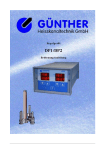
User manual control unit DP3/DP5
GÜNTHER
Hot Runner Systems
Contents:
1.
General notes
1.1 Safety information
2.
Operation
2.1 Start up
2.2 Display of temperature
2.3 Display during percentage mode
2.4 Changing the control modes (thermocouple, percentage control mode, off)
2.5 Loading default values
2.6 Fault reports
3.
Parameter setting
3.1 Parameter menu – flow chart / menu items
3.2 Configuration menu – flow start / meine items
4.
Further function
4.1 Softstart
4.2 Starting ramp
4.3 Set value lowering
4.4 Switching power control
4.5 Counter operating time
5.
Connection of control circuits
6.
Installation and start up
7.
Table of faults and defects
8.
Specifications
9.
Appendix EG – declaration of conformity
10.
Addresses
© C o p yr i g h t D AV ID S M E Y E R & P AU L Gm b H E l e k t r o n i k
2
User manual control unit DP3/DP5
GÜNTHER
Hot Runner Systems
GÜNTHER Hot Runner Control Unit DP3/DP5
1. General notes
The five zone control unit DP5 is designed for temperature regulation of five hot runner nozzles. It
may be applied for the control of any 230V-load circuit of hot runner systems. The unit’s output of
up to 3500W allows the operation of different 230V-loads by means of the ″Pulsgruppensteuerung″
(Switching Power Control).
Please note that this unit is not designed for temperature control of low voltage nozzles (5V or
24V).
On the rear the illuminated master key, the modular plug and the fuse are positionized. Each heating
circuit is controlled via solid-state-relays in ″Pulsgruppenbetrieb″ (Switching Power Control mode).
Caution !
The load fuse F3 (DP3) or F5 (DP5) may not exceed a maximum current of 16A! The other fuses
(F1-F2 for DP3 or F1-F4 for DP5) may not exceed a maximum current of 10A.
The 3-zone controller unit DP3 is a smaller version of the 5-zone control unit DP5. It is basically
constructed like the DP5, yet it operates only one circuit.
1.1 Safety information
The DP3/DP5 is built and tested according to safety standards declared by the European Council of
Assimilation of Legal Regulations (cf. appendix) and has left the factory in perfect condition. In
order to maintain this condition and for safe operation, please read this User Manual carefully and
follow the instructions.
Ensure that your local supply voltage corresponds to the unit’s nominal voltage before you switch
on. For safe operation, the unit must be plugged into an earthed socket. Any disconnection of the
earthed conductor, e.g. by using an extension flex without earthed conductor, may cause severe
danger!
Caution:
Always disconnect the unit before opening! Pull mains plug!
This control unit contains hazardous voltage. Any repair and service work must be carried out by
qualified and authorised personnel only. The components inside the unit are maintenance-free for
our customers. They are exclusively serviced by Günther Hot Runner Systems.
For operation of the control unit, a fuse protected socket must be used. Both the DP3 and DP5 are
equipped with a one phase 16A-plug. Please ensure that the sockets used are protected sufficiently.
Note:
Refer to the chapter on installation and start-up for further information. Always unplug the unit
before touching the components inside! (Pull mains plug!)
P r o d u c t i o n In d e x A, d o c u m e n t a t i o n r e v . 1 0 / 0 1
3
GÜNTHER
User manual control unit DP3/DP5
Hot Runner Systems
2. Operation
zone 1
zone 2
zone 3
zone 4
zone 5
DP5
1
2
100
102°
3
100
102°
100
102°
4
5
100
102°
100
102°
actual temp
set temp
up/down keys
MENU
°C/F
A2 B2
A1 B1
menue key
A3 B3
A4 B4
A5 B5
value lowering
The set temperature can be adjusted by pressing the up- and down-keys at each zone. You can
switch between the three operation modes by pressing the two keys (A_ and B_) of a zone
simultaneously.(See chapter 2.4)
If you change settings in the parameter menu, the left display shows the parameter settings for all
zones.
The fault reports of each zone are displayed on the defect zone display.
You enter the parametermenu by pressing key menu (see chapter 3).
By the three-zone version DP3, the 4th and the 5th display has no function. Besides that, the
functions don’t differ.
2.1 Start up
dP5
P1.03
After switching on, the controller’s left LED display (zone 1) shows the
start report: the top line indicates the number of zones connected to the
controller (DP5 – five zone controller); the bottom line indicates the
number of software version. After the start report, the DP3/DP5
automatically runs a system check then starts the operating mode.
© C o p yr i g h t D AV ID S M E Y E R & P AU L Gm b H E l e k t r o n i k
4
User manual control unit DP3/DP5
GÜNTHER
Hot Runner Systems
2.2 Display of temperature
The temperature controller displays temperatures on five 4-digit LED displays. During
thermocouple control mode, the first line displays the actual temperature and the second line
displays the set temperature (max. 500°C).
The DP3/DP5 offers the opportunity to choose between °C and °F. A set value of 570°F, for
example, would be displayed as „570F“ on this set value indicator.
2.3 Display during percentage control modes
The DP3/DP5 can be operated in percentage control mode in order to avoid a long-term production
halt in the event of a thermocouple failure.
percentage control mode: range of 0-100% possible
Keys:
Key A1..A5: Decrease the percent value (set value current control)
Key B1..B5: Increase the percent value (set value current control)
2.4 Changing the control modes
The DP3/DP5 can be operated in percentage control mode in order to avoid a long-term production
halt in the event of a thermoelectric couple failure. By pressing the keys A1 and B1 for zone 1 (or
keys A2 and B2 for zone 2 ...) simultaneously you can switch between thermocouples, percentage
control mode and zone off.
Note:
If the DP3/DP5 detects a damaged or disconnected thermocouple during operation, it
automatically disconnects the heater circuit and displays a fault report. If you confirm this
report, the unit afterwards automatically switches into percentage control mode.
2.5 Loading default values
The system parameters of the DP3/DP5 can be set in the parameter menu. In case of an error in your
parameter configuration, the unit offers the possibility to load standard default values. For that
purpose, hold down keys A1,B1 and menu during power-on of the control unit.
display
LOAd
dEF.
meaning
The display ´load defaults´ appears after you choose to set the factory
defaults for approx. 5 sec.
2.6 Fault reports
During its operation, the controller DP3/DP5 runs serval diagnostic routines. These includes
checking the thermocouples. Any fault or defect will be indicated by a short report. The heater
circuit will always be disconnected in case of a fault or defect.
Note:
System faults can be confirmed by pressing key ‚menu‘.
P r o d u c t i o n In d e x A, d o c u m e n t a t i o n r e v . 1 0 / 0 1
5
User manual control unit DP3/DP5
GÜNTHER
Hot Runner Systems
The following fault reports may arise during the operation of the DP3/DP5:
display
No
Sens
Pol.
tH.1
meaning
Thermocouple failure
The unit detected that a thermocouple is unconnected or interrupted on one wire.
Please check the wiring of your thermocouple!
Polarity error at thermocouple connection
Polarity error at the connection of thermocouple of control circuit 1. The
thermocouple seem´s to be connected with wrong polarity. Please check the
wiring of your thermocouple!
Note:
If you confirm by pressing key menu after fault report thermocouple damaged or polarity
error the DP3/DP5 automatically switches into percentage control mode. If you are able to
solve the problem the fault before confirming with key menu the controller remains in
thermocouple control mode.
Thermocouple short circuit
Err.
A short circuit in control circuit 1 has occurred. This fault can be detected after a
tH.1
period of min. 90 sec.. Please check the wiring of your thermocouple!
Over temperature
The temperature of control circuit 1 crosses the security mark. The max. allowed
t.Hi
temperature can be set as systemparameter and is standardly set to 500°.
Ch1
Err.
Temp
Ambient temperature above limit
The unit detected an ambient temperature of above 70°C.
3. Parameter setting
The operation of the controller depends on the setting of the parameters. For easy access, the most
important parameters are displayed on a menu. The parameter menu is divided into a user menu and
a configuration menu, the access to which is restricted by a password. In the user menu only noncritical system parameters can be changed.
Caution:
The access to configuration data is protected by a password. The configuration should only be
changed by authorised and qualified personnel. Inexpert configuration may cause damage of
the hot runner system. The person who sets unit into operation is responsible for correct
configuration of the controller.
© C o p yr i g h t D AV ID S M E Y E R & P AU L Gm b H E l e k t r o n i k
6
GÜNTHER
User manual control unit DP3/DP5
Hot Runner Systems
3.1 Flow chart of parameter menu
operation mode
100°
120°
display temperature
MENU
exit parameter menue
qUIt
-no
MENU
softstart ON/OFF
SoFt
-no
SoFt
ra
er
SoFt
No
MENU
YES
softstart ON
softstart OFF
MENU
set lowering temperature
rEd°
-no
rEd°
er
rEd°
er er
0040
MENU
0050
old lowering temp
new lowering temp
MENU
starting
configuration menue
ConF
- no
ConF
ra
er
h
configuration menue
---password
MENU
legend
MENU
press menu key
press A1 or B1 key
change setting by pressing A1 or B1 key
qUIt
A
e
no
kt
P r o d u c t i o n In d e x A, d o c u m e n t a t i o n r e v . 1 0 / 0 1
display
7
User manual control unit DP3/DP5
GÜNTHER
Hot Runner Systems
You enter the parameter menu by pressing key F. Each further use of this key F leads you to the
next menu item. With keys A1 or B1 you can activate each menu item. The display then switches
from no to YES.
For information on the configuration menu please refer to chapter 3.3.
display
qUIt
SoFt
rEd°
rEdA
ConF
meaning
exit menu
You can quit the parameter menu by selecting quit. Press key A1 or B1 if you
want to return to the normal operating level. You automatically quit the
parametermenu, if for approx. 10 seconds no key is pressed.
softstart
You can select the softstart function for 230V nozzles by entering the menu
SOFT. Here you can enable or disable the softstart function.
set value lowering
The menu item ‚set value lowering‘ („rEd.°“ or „rEd.A“) enables you to set the
lowering temperature or the lowering current.
This function ‚set value lowering‘ is switched by the pressing the keys A1 and
F simultaneously.
configuration menu
The menu item ´configuration menue´ („CONF.“) enables you to enter the
configuration menu. This menu is protected by a password. Please refer to the
chapter 3.3
© C o p yr i g h t D AV ID S M E Y E R & P AU L Gm b H E l e k t r o n i k
8
GÜNTHER
User manual control unit DP3/DP5
Hot Runner Systems
3.2 Flow chart of configuration menu
configuration
menue
ConF
in parametermenue select configuration menue,
type your password and press menue
---MENU
adjust PID parameter
of zone 1
PId1
iv
-no
MENU
adjust PID parameter
of zone 2..5
HP 1
iv iv
MENU
60
Hi 1
MENU
20
Hd 1
MENU
70
1..4 times
PId2..5
s
iv
-no
HP 2..5
siv siv
MENU
60
Hi 2..5
iv iv
MENU
20
Hd 2..5
iv iv
MENU
er er
MENU
70
MENU
temperature
unit °C/ °F
UnIt
er
s
-no
UnIt
UnIt
er
s er
s
°C
MENU
°F
MENU
hour meter
Hour
er
iv
-no
Hour
MENU
14
MENU
adjustment system
parameter
SYS
er
siv
-no
PA01
0010
er
s er
s
MENU
PA
02..49
er
MENU
PA50
0242
MENU
exit menue
qUIt
-no
er
as
100°
operation mode
120°
MENU
P r o d u c t i o n In d e x A, d o c u m e n t a t i o n r e v . 1 0 / 0 1
9
User manual control unit DP3/DP5
GÜNTHER
Hot Runner Systems
In the configuration menu, the system parameters of controller DP3/DP5 can be set. Besides the
various items for frequently used parameters, the item ‚system‘ is therefore protected by an
additional password. Changes of system parameters must be carried out by authorised and qualified
personnel.
display
ConF
----
Pid1..5
UnIt
Hour
SYS
qUIt
meaning
configuration menu
You find the configuration menu in the parameter menu item (‚CONF.‘).
To start the configuration menu you must enter the password. You have to
enter the digits of the passwords starting right by pressing A1 or B1. Enter by
pressing the F key.
PID parameters
Item PID_ allows to change the PID regulation parameters for each zone
manually. At the five zone controller DP5 there are five menu items to select
the PID parameters each zone.
temperature unit
In the menu item temperature unit you can choose between °C (Celsius) and °F
(Fahrenheit).
counter operating time
In the menu item hour you can find the number of operating hours.
system parameters
The system parameters of the DP3/DP5 can be changed after entering the
menu item ‚sys‘. The menu is protected by a password and enables you to set
and change all system parameters. Changes of the system parameters should
only be carried out by authorised and qualified personnel.
You can load the standard default values as described in chapter 2.5, if your
configuration of the system parameters proves inadequate or faulty.
exit menu
You can quit the parameter menu by selecting quit. Press key A1 or B1 if you
want to return to the normal operating level. You automatically quit the
parametermenu, if for approx. 10 seconds no key is pressed.
© C o p yr i g h t D AV ID S M E Y E R & P AU L Gm b H E l e k t r o n i k
10
User manual control unit DP3/DP5
GÜNTHER
Hot Runner Systems
4. further functions
4.1 Start up procedure
With 230V loads connected to a system, a softstart is necessary in order to remove the moisture
from the thermoelectric couples. During the first phase of the softstart, the set value n per cent is
increased from 0 to 50%. The ramp time is adjustable – any adjustment must guarantee that at the
end of the ramp a temperature of 105°C will be reached. During the hold time following this
procedure, the DP3/DP5 sets the temperature to 105°C independent of the set value selected. During
the hold time, the nozzles are dried out adequately, while keeping the thermic load as low as
possible. The system performs the start-up procedure automatically after the control unit is switched
on. The unit switches into normal operating condition immediately after the hold time.
4.2 Starting ramp
If you wish to heat up a cool zone, it is highly recommended that you do not use the max. power for
reaching the desired operating temperature. The DP3/DP5 limitates the power output at the initial
start-up and afterwards increases it to 100% over four steps, in order to keep the thermic stress as
low as possible. After approx. 60 seconds the max. heating capacity is available.
4.3 Temperature lowering
During any long-term production halt it is advisable to lower the temperature of the zones. It is not
necessary to adjust the temperature for each regulation zone – you can control the temperature of all
zones simultaneously by pressing a lowering-hotkey . If you press the value lowering key °C↓, the
set temperatures of all zones is lowered by a preset value. You can cancel the lowering by pressing
the lowering key again.
4.4 Switching power control
The above mentioned phase control mechanism for continuous output control is provided
specifically for hot runner nozzles. For the operation of 230V-heater circuits with very high output,
the DP3/DP5 provides the Switching Power Control. The switching power control triggers a solid
state relay. This way the 230V-heater circuits with just about any load can be controlled.
The Switching Power Control ensures that the desired output will practically continuously be
activated. It´s main advantage over a traditional controller is an improvement of heating capacity,
and thus better control qualities.
4.5 Counter operating time
The operating time of the DP3/DP5 is internally saved with resolution of 1 minute and may be read
via the parameter menu.
operating time < 10 hours display : hours.min
operating time ≥ 10 hours display:
hours
P r o d u c t i o n In d e x A, d o c u m e n t a t i o n r e v . 1 0 / 0 1
11
GÜNTHER
User manual control unit DP3/DP5
Hot Runner Systems
5. Connection of control circuits
On the rear of control unit a load connection plug is positioned. On this modular plug, up to 2 load
connection modules can be assembled, depending on the version (DP1 or DP2). Each 230V-load
circuit will be connected using these solid 20A-contacts. Refer to fig. 3.2 for information about the
assignment of the connection points to the corresponding modules.
zone
load 1 (phase)
load 2 (neutral)
thermo +
thermo -
1
1
2
13
14
2
3
4
15
16
3
5
6
17
18
4
7
8
19
20
5
9
10
21
22
6. Installation and start-up
a) Installation
• Please position the unit where not heat accumulation will occur.
• Ensure that the sockets are sufficiently for connecting.
The DP1 and DP2 needs a 16A-Schuko mains plug
• The load fuse may not exceed 16A.
b) Start-up
• To connect the heating circuit and thermocouples, plug in load connectors.
• Plug in mains plug for power supply.
• Press power switch.
• Set the desired set temperatures of all zones.
• During initial start-up you should activate each control point separately so that possible faulty
connection of either load or thermoelectric couple may be detected.
• After switching on the control unit, please wait for a few minutes until all tools are heated up
evenly.
© C o p yr i g h t D AV ID S M E Y E R & P AU L Gm b H E l e k t r o n i k
12
GÜNTHER
User manual control unit DP3/DP5
Hot Runner Systems
7. Table of faults and defects
During the course of the operation, the DP3/DP5 is continually checking the control circuit for
faults and defects. Any fault/defect detected is indicated on the display.
A
Fault report
”no sensor 1”
Fault/Defect
Thermocouple of
zone 1 or 3 defect
B
Fault report
”no sensor 2”
Thermocouple of
zone 2 or 4 defect
C
Fault report
”Pol. TH 1”
D
Fault report
”Pol. TH 2”
Polarity error at
thermocouple of
zone 1 or 3
Polarity error at
thermocouple of
zone 1 or 3
E
Significant fluctuation of temperature
(+/- 100 °C )
Temperature increase
not satisfactory
F
Possible Cause
Thermocouple is not
connected or
interrupted
Thermocouple is not
connected or
interrupted
Polarity error at the
thermo couple
Countermeasure
Check connection plug
and -cable of
thermoelectric couple
Check connection plug
and –cable of
thermoelectric couple
Correct the polarity
Polarity error at the
thermo couple
Correct the polarity
Thermocouple defect
Check earthing of load
or load circuit not
circuit
earthed
Load circuit (swapped) Check assignment of
heater circuit to
thermoelectric couple
Caution:
With 230V-runners the heater circuits must be earthed sufficiently. Lack of earthing or
insufficiently earthed tool/heating element may cause several errors in the temperature reading.
Note:
During initial start-up the assignment of the zones must be checked. For that purpose you should
heat up the control circuits one by one and monitor the temperature rise.
P r o d u c t i o n In d e x A, d o c u m e n t a t i o n r e v . 1 0 / 0 1
13
GÜNTHER
User manual control unit DP3/DP5
Hot Runner Systems
8. Specifications
Nominal Voltage:
220V – 240V AC, 50/60Hz
Nominal Capacity DP3/5:
3500 W, 1 x 16A
Stand-by Capacity :
approx. 10 VA
Load Connection DP3:
2 x heater circuit 230V / 10A (zone 1-2)
1 x heater circuit 230V / 16A (zone 3)
amphenol modular connector series C146...
Load Connection DP5:
4 x heater circuit 230V / 10A (zone 1-4)
1 x heater circuit 230V / 16A (zone 5)
amphenol modular connector series C146...
Mains Plug DP3/DP5:
3m, 16A-plug
Thermocouple Connection: thermoelectric couple type L (FeCuNi),
amphenol modular connector series C146...
Fuses:
FF 16A, 6,3 x 32mm, type Schurter Typ SA; superfast for triacs
FF 10A, 6,3 x 32mm, type Schurter Type SA; superfast for triacs
Regulation:
″Pulsgruppensteuerung″ (switching power control)
Storage Temperature:
up to 70°C
Operating Temperature:
up to 35°C
Protection Type:
IP 20
Dimensions (W, H, D):
259mm x 95mm x 290mm
Colour:
grey and blue (RAL 9018 and RAL 5015)
© C o p yr i g h t D AV ID S M E Y E R & P AU L Gm b H E l e k t r o n i k
14
D avidsmeyer & Paul
P aul Gmb
G mbH
mb H
9. Appendix: EG- declaration of conformity
For the following below listed products:
GÜNTHER-Hot Runner Controller DP3 and DP5
we hereby confirm, that above listed products comply to all important (*) safety requirements
that have been declared by the Council of Assimilation of Legal Regulations by the EC
membership countries concerning electromagnetical conformity (89/336/EWG).
To verify these products to electromagnetical conformity the following standards were
referred to:
EN 50081, Part 2
EN 50082, Part 2
The above mentioned products also comply to:
DIN EN 61010, part 1/03.94.
This declaration applies to all above listed products with the following production index:
Production Index A
The production index is the number behind the serial number on the identification label of
the product. The identification label is located on the right side of the product.
DAVIDSMEYER & PAUL GmbH Elektronik
Technologiezentrum
Karl-Heinz-Beckurts-Str.13
D-52428 Jülich
Jülich, 01.09.2000
J. Marquardt
(Managing Director)
(*) Expressions recommended by "EMV-Rechtsvorschriften und ihre Anwendung in der Praxis", Franzis-Verlag, 1993
P r o d u c t i o n In d e x A, d o c u m e n t a t i o n r e v . 0 9 . 0 0
15
GÜNTHER
User manual control unit DP3/DP5
Hot Runner Systems
10. Adresses
(HEADQUARTER)
GÜNTHER Heisskanaltechnik GmbH
Industriegebiet Nord
Sachsenberger Straße 1
D-35066 Frankenberg (Eder)
Germany
Phone
Fax
E-mail
Internet
(++ 49) 64 51 50 08 0
(++ 49) 64 51 50 08 50
[email protected]
www.guenther-hotrunner.com
Germany
Phone / Fax / E-mail
GÜNTHER Heisskanaltechnik GmbH
Mr. Spork
Sachsenberger Str. 1
D-35066 Frankenberg
Phone
Fax
E-mail
(++ 49) 01 73 8 67 83 35
(++ 49) 64 51 50 08 59
[email protected]
GÜNTHER Heisskanaltechnik GmbH
Mr. Stamm
Sachsenberger Str. 1
D-35066 Frankenberg
Phone
Fax
E-mail
(++ 49) 01 72 9 41 12 26
(++ 49) 64 51 50 08 59
[email protected]
Verkaufsbüro Baden-Württemberg Nord
Mr. Fritz
Zedernstr. 23
D-64653 Lorsch
Phone
Fax
E-mail
(++ 49) 62 51 55 03 82
(++ 49) 62 51 55 03 83
[email protected]
Verkaufsbüro Baden-Württemberg Mitte
Mr. Rasi
Sonnenweg 4
D-74372 Sersheim
Phone
Fax
E-mail
(++ 49) 70 42 37 48 48
(++ 49) 70 42 37 48 49
[email protected]
Verkaufsbüro Baden-Württemberg Süd
Mr. Waizmann
Mühlenstraße 21
D-79367 Weisweil
Phone
Fax
E-mail
(++ 49) 76 46 91 54 90
(++ 49) 76 46 91 54 91
[email protected]
WESCHU
Mr. Grajer
Edisonstr. 81
D-90431 Nürnberg
Phone
Fax
E-mail
(++ 49) 911 96 12 30 0
(++ 49) 911 96 12 30 50
[email protected]
Industrievertretungen
Mr. Römhild
Thomas-Mann-Str. 4
D-98597 Breitungen
Phone
Fax
E-mail
(++ 49) 36 84 88 68 0
(++ 49) 36 84 88 68 22
[email protected]
Verkaufsbüro Nord
Herr Dierks
Mittelfeldweg 19a
D-27607 Langen
Phone
Fax
E-mail
(++ 49) 47 43 91 29 90
(++ 49) 47 43 91 29 91
[email protected]
P r o d u c t i o n In d e x A, d o c u m e n t a t i o n r e v . 1 0 / 0 1
17
GÜNTHER
User manual control unit DP3/DP5
Hot Runner Systems
Worldwide
Phone / Fax / E-mail
GÜNTHER France S.A.
Mr. Demicheli
6 rue Jules Verne
F-95320 Saint Leu La Foret
Phone
Fax
E-mail
(++ 33) 1 39 32 03 04
(++ 33) 1 39 32 03 05
[email protected]
GÜNTHER U.K.
Mr. Heendeniya
52 Lambardes, New Ash Green
GB-Longfield Kent DA3 8HU
Phone
Fax
E-mail
(++ 44) 14 74 87 97 74
(++ 44) 14 74 87 30 63
[email protected]
Trader Ingman Oy
Mr. Ingman
Strömsintie 23 A 1
FIN-00930 Helsinki
Phone
Fax
E-mail
(++ 358) 93 44 55 44
(++ 358) 93 43 40 52 0
[email protected]
GÜNTHER Hot Runner Systems Inc.
Mr. Vander Noot
725 Hastings Lane
USA-Buffalo Grove, Illinois 60089
Phone
Fax
E-mail
(++ 1) 84 72 15 78 74
(++ 1) 84 72 15 78 05
[email protected]
Federal Technology Corp.
Mr. Yun
6F, No. 74 FU Shiang St.,
Chyan-Jenn Dist.
Kaohsiung 806
Taiwan R.O.C.
Phone
Fax
E-mail
(++ 886) 7-72 10 17 1
(++ 886) 7-75 12 27 0
[email protected]
Su-Pad Ltd.
Mr. Sadeh
2, Hamelacha Street
New Industrial Zone
IL-Rosh-Ha´ Ayn 48091
Phone
Fax
E-mail
(++ 972) 3 90 23 90 2
(++ 972) 3 90 23 90 3
[email protected]
Dipl.-Ing. Petr Sochor
Ve Vilkách 1849
CZ-347 01 Tachov
Phone
Fax
E-mail
(++ 42 0) 1 84 72 39 66
(++ 42 0) 1 84 72 39 66
[email protected]
GÜNTHER S.C.
Mr. Olszowski
ul. Poznańska 14 m 33
PL-00-680 Warszawa
Phone
Fax
E-mail
(++ 48) 22 62 25 22 8
(++ 48) 22 62 97 77 4
[email protected]
Dipl.-Ing. H. Günther Ges.m.b.H.
Mr. Feik
Speichmühlgasse 1
A-2380 Perchtoldsdorf
Phone
Fax
E-mail
(++ 43) 1 86 94 76 4
(++ 43) 1 86 94 76 47
[email protected]
Basler Trade KFT
Mr. Zastrow
Postbox 25
H-1581 Budapest
Phone
Fax
E-mail
(++ 36) 12 39 05 17
(++ 36) 12 39 05 17
[email protected]
P.E.P. Plastics GmbH
Mr. Elmer
Wülflingerstrasse 59, P.O.Box 21
CH-8407 Winterthur
Phone
Fax
E-Mail
(++41) 52 222 72 26
(++41) 52 222 07 24
[email protected]
© C o p yr i g h t D AV ID S M E Y E R & P AU L Gm b H E l e k t r o n i k
18
GÜNTHER
User manual control unit DP3/DP5
Hot Runner Systems
Worldwide
Phone / Fax / E-mail
Grupo Zoica
Eduardo Campos Madrigal
S.A. de V. C. Sadi Carnot No. 77
Col. San Rafael
MEX-D. F. 06470 Delg. Cuauhtemco
Phone
Fax
E-mail
(++ 52) 55 46 40 14
(++ 52) 55 66 61 62
[email protected]
Center Plast
Mr. Gonzalez-Palacio
C/ Sant Gabriel, 17 Lo. 3
E- 08950 Esplugues de Liob.
Phone
Fax
E-mail
(++ 34) 93 47 37 71 3
(++ 34) 93 49 90 43 8
[email protected]
Technisches Büro Bäcker
Mr. Bäcker
Pieter Lieftinckweg 20
NL-1505 HX Zaandam
Phone
Fax
E-mail
(++ 31) 75 68 18 00 0
(++ 31) 75 68 18 00 1
[email protected]
Battenfeld Hong Kong Ltd.
Mr. Pechtl
2Fl. No.18 Dai Fat Street
Tai Po Industrial Estate
Hong Kong-N.T. Tai Po
Phone
Fax
E-mail
(++ 852) 26 66 91 40
(++ 852) 26 65 25 26
[email protected]
Millutensil SRL
Mrs. Just Oselieri
Corso Buenos Aires 92
I-20124 Milano
Phone
Fax
E-mail
(++ 39) 02 29 40 43 90
(++ 39) 02 20 46 67 7
[email protected]
Brale Ltda.
Mr. Holdschmidt
Rua Joao de Barro, 52
BR-83326-470 Pinhais-PR
Phone
Fax
E-mail
(++ 55) 41 66 82 59 5
(++ 55) 41 66 82 59 5
[email protected]
DUMIS Mlaka d.o.o.
Mr. Urana
Oretnekova pot 9
SL-4000 Kranj
Phone
Fax
E-mail
(++ 386) 42 74 10 00
(++ 386) 42 74 10 01
[email protected]
HH Plastkombi aps
Mr. Hansen
Østergade 24 D
DK-3200 Helsinge
Phone
Fax
E-mail
(++ 45) 48 79 98 88
(++ 45) 48 79 80 16
[email protected]
DELPLACE. Ltd
Marc Delplace B. Sc.Eng.
6061 Thimens Boulevard
CAN-St-Laurent, QC H4S 1V8
Phone
Fax
E-mail
(++1) 51 44 85 77 80
(++1) 51 44 85 11 28
[email protected]
© C o p yr i g h t D AV ID S M E Y E R & P AU L Gm b H E l e k t r o n i k
18