1
1473-1-7965 │ 04.04.2014
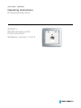
Operating Instructions
IP-Netzwerktechnik
Pos: 2 /#Neustruktur#/Online-Dokumentation (+KNX)/Titelblätter/Sonstige Bereiche/Titelblatt - 8186-31 @ 38\mod_1386240204434_15.docx @ 300980 @ @ 1
8186/31
WLAN access point,
flush-mounted
Software version 1.0.0.3
=== Ende der Liste für Textmarke Cover ===
Operating Instructions
IP-Netzwerktechnik
Pos: 4 /#Neustruktur#/Online-Dokumentation (+KNX)/Inhaltsverzeichnis (--> Für alle Dokumente <--)/Inhaltsverzeichnis @ 19\mod_1320649044386_15.docx @ 109653 @ @ 1
1 2 3 4 5 6 7 8 Safety....................................................................................................................................................................... 4 Intended use ............................................................................................................................................................ 4 Environment ............................................................................................................................................................. 4 Technical data and settings ..................................................................................................................................... 5 4.1 Technical data ......................................................................................................................................... 5 4.2 Factory settings ....................................................................................................................................... 6 Information about licenses ....................................................................................................................................... 7 Setup and function ................................................................................................................................................... 8 6.1 General description ................................................................................................................................. 8 6.2 Types of functions ................................................................................................................................... 8 6.2.1 Single mode access point ....................................................................................................................... 8 6.2.2 Access point for extending an installation around WLAN ........................................................................ 9 6.2.3 Operation with several access points .................................................................................................... 10 6.2.4 Increase in the range of WLAN (with WDS) .......................................................................................... 11 6.2.5 Increase in the range of WLAN (without WDS) ..................................................................................... 13 6.2.6 Operation with several access points as separate WLAN networks ..................................................... 15 6.3 Range of transmitting power ................................................................................................................. 17 Installation and electrical connection ..................................................................................................................... 18 7.1 Requirements for the electrician ........................................................................................................... 18 7.2 Mounting ............................................................................................................................................... 19 7.3 Electrical connection ............................................................................................................................. 19 7.3.1 Connecting mains power....................................................................................................................... 19 7.3.2 Connecting the network cable ............................................................................................................... 20 Commissioning ...................................................................................................................................................... 21 8.1 Initial connection ................................................................................................................................... 21 8.2 Configuration ......................................................................................................................................... 22 8.2.1 General ................................................................................................................................................. 22 8.2.2 Logon .................................................................................................................................................... 23 8.2.3 Password setting ................................................................................................................................... 23 8.3 Configuration – System – General ........................................................................................................ 24 8.3.1 System settings ..................................................................................................................................... 24 8.3.2 General system settings........................................................................................................................ 24 8.4 System/Status configuration ................................................................................................................. 24 8.4.1 System language .................................................................................................................................. 25 8.5 Status configuration .............................................................................................................................. 26 8.5.1 Status information ................................................................................................................................. 26 8.6 Network configuration ........................................................................................................................... 27 8.6.1 Network IP settings ............................................................................................................................... 27 8.6.2 Network - IP settings - Settings ............................................................................................................. 28 8.7 WLAN network ...................................................................................................................................... 29 8.7.1 Network - WLAN settings ...................................................................................................................... 31 8.7.2 Network – WLAN settings – Device configuration - General settings .................................................... 31 8.7.3 Network – WLAN settings – Interface configuration - General settings ................................................. 32 8.7.4 Network – WLAN settings – Device configuration - General settings .................................................... 32 8.7.5 Network – WLAN settings – Device configuration - Extended settings ................................................. 33 8.7.6 Interface configuration – WLAN encryption ........................................................................................... 34 8.7.7 Network diagnostics .............................................................................................................................. 34 8.8 Configuration – System – Backups/Updates ......................................................................................... 35 8.8.1 System – Backup/Software-Update ...................................................................................................... 35 8.8.1.1 Backup/Restore .................................................................................................................................... 36 8.8.1.2 Installing new Firmware ........................................................................................................................ 36 8.8.2 Reboot .................................................................................................................................................. 37 8.8.3 Log off ................................................................................................................................................... 37 8.9 Configuration – Expert information ........................................................................................................ 37 8.9.1 Expert diagram ...................................................................................................................................... 37 Operating Instructions | 1473-1-7965
—2—
Operating Instructions
IP-Netzwerktechnik
9 10 11 8.9.1.1 LAN1 ..................................................................................................................................................... 37 8.9.1.2 WLAN.................................................................................................................................................... 37 Operation ............................................................................................................................................................... 38 9.1 Controlling the flush-mounted WLAN access point via UDP ................................................................. 38 9.2 Meaning of the LEDs............................................................................................................................. 39 9.3 Reset functions ..................................................................................................................................... 39 9.3.1 Reset to factory settings........................................................................................................................ 39 9.3.2 Full reset ............................................................................................................................................... 40 Fault rectification .................................................................................................................................................... 41 Glossary ................................................................................................................................................................. 42 === Ende der Liste für Textmarke TOC ===
Operating Instructions | 1473-1-7965
—3—
Operating Instructions
IP-Netzwerktechnik
Safety
Pos: 6 /#Neustruktur#/Online-Dokumentation (+KNX)/Überschriften (--> Für alle Dokumente <--)/1. Ebene/S - T/Sicherheit @ 18\mod_1302612791790_15.docx @ 103357 @ 1 @ 1
1
Safety
Pos: 7 /#Neustruktur#/Online-Dokumentation (+KNX)/Sicherheitshinweise und Hinweise (--> Für alle Dokumente <--)/Warnhinweise/Sicherheit - 230 V @ 18\mod_1302606816750_15.docx @ 103308 @ @ 1
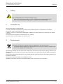
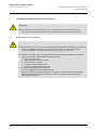
Warning
Electric voltage!
Risk of death and fire due to electrical voltage of 230 V.
– Work on the 230V supply system may only be performed by authorised electricians!
– Disconnect the mains power supply prior to installation and/or disassembly!
Pos: 8 /#Neustruktur#/Online-Dokumentation (+KNX)/Überschriften (--> Für alle Dokumente <--)/1. Ebene/A - F/Bestimmungsgemäßer Gebrauch @ 18\mod_1302763321316_15.docx @ 103483 @ 1 @ 1
2
Intended use
Pos: 9 /#Neustruktur#/Online-Dokumentation (+KNX)/Bestimmungsgemäßer Gebrauch/Sonstige Bereiche/Bestimmungsgemaesser Gebrauch - 8186-31 @ 32\mod_1355394040338_15.docx @ 258814 @ @ 1
This device has three operating modes.
It can be used either as access point for wireless communicating devices or as repeater to increase the
transmission range in the WLAN network.
In addition, it can be connected as WLAN adapter via Ethernet to devices which do not have their own WLAN
connection.
To set up the device requires an external device, e.g. a laptop.
The device must only be installed in dry indoor rooms.
Pos: 10.1 /#Neustruktur#/Modul-Struktur/Online-Dokumentation/Überschriften (--> Für alle Dokumente <--)/1. Ebene/U - Z/Umwelt @ 18\mod_1302614158967_15.docx @ 103383 @ 1 @ 1
3
Environment
Pos: 10.2 /#Neustruktur#/Online-Dokumentation (+KNX)/Sicherheitshinweise und Hinweise (--> Für alle Dokumente <--)/Hinweise/Hinweis - Umwelt - Hinweis Elektrogeräte @ 18\mod_1302763973434_15.docx @ 103500 @ @ 1
Consider the protection of the environment!
Used electric and electronic devices must not be disposed of with domestic waste.
– The device contains valuable raw materials which can be recycled. Therefore, dispose of the
device at the appropriate collecting depot.
Pos: 10.3 /#Neustruktur#/Online-Dokumentation (+KNX)/Sicherheitshinweise und Hinweise (--> Für alle Dokumente <--)/Hinweise/Hinweis - Umwelt - Entsorgung Elektrogeräte @ 20\mod_1325760695972_15.docx @ 136583 @ @ 1
All packaging materials and devices bear the markings and test seals for proper disposal. Always dispose of the
packaging material and electric devices and their components via the authorized collecting depots and disposal
companies.
The products meet the legal requirements, in particular the laws governing electronic and electrical devices and
the REACH ordinance.
(EU Directive 2002/96/EC WEEE and 2002/95/EC RoHS)
(EU REACH ordinance and law for the implementation of the ordinance (EC) No.1907/2006)
Pos: 11 /#Neustruktur#/Online-Dokumentation (+KNX)/Steuermodule - Online-Dokumentation (--> Für alle Dokumente <--)/++++++++++++ Seitenumbruch ++++++++++++ @ 9\mod_1268898668093_0.docx @ 52149 @ @ 1
Operating Instructions | 1473-1-7965
—4—
Operating Instructions
IP-Netzwerktechnik
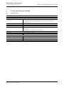
Technical data and settings
Pos: 12 /#Neustruktur#/Online-Dokumentation (+KNX)/Überschriften (--> Für alle Dokumente <--)/1. Ebene/S - T/Technische Daten und Einstellungen @ 33\mod_1360750040379_15.docx @ 277375 @ 1 @ 1
4
Technical data and settings
Pos: 13 /#Neustruktur#/Online-Dokumentation (+KNX)/Technische Daten/Sonstige Bereiche/Technische Daten - 8186-31 -- BJE @ 38\mod_1386234045722_15.docx @ 300754 @ 22 @ 1
4.1
Technical data
General
Types of functions:
Access point, Access point (WDS/Repeater), Client (WDS), Client (Relayd)
Mechanical characteristics
Dimensions (L x W x H):
80 x 80 x 50 mm
For mounting in commercially available deep flush-mounted, surface-mounted and
hollow-wall sockets.
Weight:
112 g
Protection type:
IP 20
Temperature range during operation:
-5 … 45°C
Connections:
RJ 45 (10 / 100 Mbit/s)
Screw contacts
The data rate for all connections is 10 / 100 Mbit/s
Electrical characteristics
Power supply:
100 ... 240 V AC, 50 ... 60 Hz
Power consumption:
≤ 1.8 W
WLAN characteristics
Radio range:
2.4 GHz
Radio data rates:
Maximum 150 Mbit/s
Radio standard:
IEEE 802.11 b / g / n
Security and encryption:
WEP, WPA, WPA2
Operating Instructions | 1473-1-7965
—5—
Operating Instructions
IP-Netzwerktechnik
4.2
Technical data and settings
Factory settings
Condition at delivery
Own settings
System/Administration:
Password
admin
System/System:
Hostname
BJE-WLAN surface mounted
UDP port
None
Network/LAN/Settings:
Protocol
Static address
IPv4 address
192.168.55.1
IPv4 netmask
255.255.0.0
IPv4 gateway
None
DNS Server
None
Network/WLAN/Settings:
The WLAN network is activated
Yes
Channel
Auto
Transmitting power:
100 %
ESSID
BJE WLAN surface-mounted
Mode
Access point
Hide ESSID
No
Network/Extended settings:
Mode
Auto
HT mode
20 MHz
Network/WLAN/WLAN encryption:
Encryption
WPA-PSK/WPA2-PSK Mixed
Cipher
Auto
Key
PleaseChange
Mode
Network/Diagnostics:
Ping
None
Notes
Pos: 15 /#Neustruktur#/Online-Dokumentation (+KNX)/Steuermodule - Online-Dokumentation (--> Für alle Dokumente <--)/++++++++++++ Seitenumbruch ++++++++++++ @ 9\mod_1268898668093_0.docx @ 52149 @ @ 1
Operating Instructions | 1473-1-7965
—6—
Operating Instructions
IP-Netzwerktechnik
Information about licenses
Pos: 16 /#Neustruktur#/Online-Dokumentation (+KNX)/Überschriften (--> Für alle Dokumente <--)/1. Ebene/G - L/Lizenzhinweise @ 38\mod_1386234540127_15.docx @ 300883 @ 1 @ 1
5
Information about licenses
Pos: 17 /#Neustruktur#/Online-Dokumentation (+KNX)/Linzenzhinweise/Lizenzhinweise - 8186-31 -- BJE @ 38\mod_1386234659526_15.docx @ 300899 @ @ 1
Parts of the firmware are subject to the GNU General Public License.
License Information
This product includes software of third-party suppliers subject to the terms of licence of the GNU General Public
License. You may change or distribute this free software subject to the terms of the GNU General Public License.
Availability of the source code
Upon request we will send you the entire source code of the software licenced under the GNU General Public
License - including all scripts, to control the compilation and installation of the drivers. You can also download it
from the e-catalogue (www.busch-jaeger-katalog.de).
Pos: 19 /#Neustruktur#/Online-Dokumentation (+KNX)/Steuermodule - Online-Dokumentation (--> Für alle Dokumente <--)/++++++++++++ Seitenumbruch ++++++++++++ @ 9\mod_1268898668093_0.docx @ 52149 @ @ 1
Operating Instructions | 1473-1-7965
—7—
Operating Instructions
IP-Netzwerktechnik
Setup and function
Pos: 20 /#Neustruktur#/Online-Dokumentation (+KNX)/Überschriften (--> Für alle Dokumente <--)/1. Ebene/A - F/Aufbau und Funktion @ 11\mod_1279185435352_15.docx @ 83027 @ 2 @ 1
6
Setup and function
Pos: 21 /#Neustruktur#/Online-Dokumentation (+KNX)/Aufbau und Funktion/Sonstige Bereiche/Funktionen - 8186-31 -- BJE @ 38\mod_1386234133531_15.docx @ 300786 @ 122333333 @ 1
6.1
General description
The flush-mounted WLAN access point offers an excellent alternative for meeting the demands made on modern
infrastructures according to DIN 18015-2 and RAL-RG 678, without having to go without the convenient use of
modern, mobile technology such as tablet PCs or laptops and without limiting the transmission data rates.
Additionally, the flush-mounted WLAN access point functions like a normal data socket with an RJ45 output for a
conventional data terminal device (data rate up to 100 Mbit/s). The power is supplied direct via 230 V at the rear
of the device.
The flush-mounted WLAN access point can be connected to the internal data network via a classic network cable.
The transmission range of the WLAN can be adapted and limited to the conditions of the room. This creates highperformance radio cells in the room, which ensure a maximum radio band width within the room while operating at
minimal power consumption and radiation.
Due to the minimum requirement for energy and resultant minimum radio emission, demarcation problems under
individual access points and overcoupling of WLAN areas and reduction of data rates are largely avoided.
6.2
Types of functions
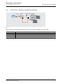
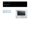
6.2.1
Single mode access point
WLAN access point, FM
Router
Internet
Fig. 1:
Internet coupling of terminal devices in the house via WLAN and RJ45 socket
•
Hard-wired network coupling
•
Interface to the LAN/Internet
Mode
Access point
SSID
Free selection
Ip
192.168.x.x
Encryption
Free selection
Channel
1-13
Operating Instructions | 1473-1-7965
—8—
Operating Instructions
IP-Netzwerktechnik
6.2.2
Setup and function
Access point for extending an installation around WLAN
Splitter
WLAN access point, FM
Router
Internet
Fig. 2:
Internet coupling of terminal devices via WLAN for use in an existing installation with patch cable.
Mode
Access point
SSID
Free selection
Ip
192.168.x.x
Encryption
Free selection
Channel
1-13
Operating Instructions | 1473-1-7965
—9—
Operating Instructions
IP-Netzwerktechnik
6.2.3
Setup and function
Operation with several access points
WLAN access point, FM
Router
Switch
Internet
1)
WLAN access point, FM
2)
to further
WLAN access points, FM
Fig. 3:
Operation of several flush-mounted WLAN access points via a switch
•
Hard-wired network coupling
•
Interface to the LAN/Internet
(1)
Mode
Access point
SSID
Free selection
Ip
192.168.x.x
Encryption
Free selection
Channel
1-13
(2)
Mode
Access point
SSID
Free selection
Ip
192.168.x.x
Encryption
Free selection or roaming
Channel
1-13
Operating Instructions | 1473-1-7965
— 10 —
Operating Instructions
IP-Netzwerktechnik
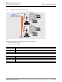
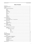
6.2.4
Setup and function
Increase in the range of WLAN (with WDS)
WLAN access point, FM
Base station (ESSID)
WLAN access point, FM
and
BSSID)
Client (ESSID
(EESSID
and
BSSID) (BSSID)
WDR
Fernsehen
12:59
WDR
Fernsehen
12:59
Router
Internet
Fig. 4:
Connection of two network segments via WLAN
•
Increase in the range of WLAN-capable devices
•
Interface to the LAN/Internet
Base station:
Mode
Access point (WDS/Repeater)
SSID
Free selection
Ip
192.168.x.x
Encryption
Free selection
Channel
1-13
Client:
Network interface 1
Mode
Client (WDS)
SSID
From the base station
Ip
192.168.x.y
Encryption
From the base station
Channel
From the base station
Network Interface 2
Mode
Access point
SSID
Free selection or roaming
Ip
Automatic
Encryption
Free selection or roaming
Channel
Automatic
Operating Instructions | 1473-1-7965
— 11 —
Operating Instructions
IP-Netzwerktechnik
Setup and function
•
•
•
The base station and client must have the same SSID.
The IP address must be located in the same area, e.g. 192.168.0.x.
The encryption must be the same.
•
The MAC address of the base station must be entered in the client in field BSSID.
Note
Both devices must be either a flush-mounted WLAN access point, or support the WDS standard.
Operating Instructions | 1473-1-7965
— 12 —
Operating Instructions
IP-Netzwerktechnik
6.2.5
Setup and function
Increase in the range of WLAN (without WDS)
Router
(ESSID)
1)
WLAN access point, FM
Client (ESSID and BSSID)
(BSSID)
Internet
2)
WDR
Fernsehen
12:59
Fig. 5:
Coupling of terminal devices to a WLAN router
•
Increase in the range of WLAN-capable devices
•
Interface to the LAN/Internet
1) Router:
Mode
Access point
SSID
Free selection
Ip
192.168.x.x
Encryption
Free selection
Channel
1-13
2) Client: Network interface 1
Mode
Client (Relayd)
SSID
From the base station
Ip
192.168.x.y
Encryption
From the base station
Channel
From the base station
Network Interface 2
Mode
Access point
SSID
Free selection or roaming
Ip
192.168.x.y
Encryption
Free selection or roaming
Channel
Automatic
Operating Instructions | 1473-1-7965
— 13 —
Operating Instructions
IP-Netzwerktechnik
Setup and function
•
•
•
The base station and client must have the same SSID.
The IP address must be located in the same area, e.g. 192.168.0.x.
The encryption must be the same.
•
The MAC address of the base station must be entered in the client in field BSSID.
Note
This type of function can be used for different devices or when the WDS standard is not supported
by the router.
Operating Instructions | 1473-1-7965
— 14 —
Operating Instructions
IP-Netzwerktechnik
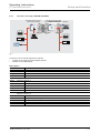
6.2.6
Setup and function
Operation with several access points as separate WLAN networks
Room 3
WLAN access point, FM
Access point
(ESSID 2)
≈
Room 2
WLAN access point, FM
Client (ESSID 1)
Room 1
Router
Internet
WLAN access point, FM
Base station
(ESSID 1)
Fig. 6:
Operating Instructions | 1473-1-7965
— 15 —
Operating Instructions
IP-Netzwerktechnik
Setup and function
Inter-room use of the Internet via WLAN
•
Interface to the LAN/Internet
•
The same SSID for client and base station (room 1 and 2)
•
Other SSID for room 3
•
The same encryption for all rooms
•
The same area for IP address for client and base station (room 1 and 2)
Room 3:
Mode
Only access point is possible
Room 2:
Mode
Client (WDS) with virtual access point (see also chapter 6.2.4)
Room 1:
Mode
Access point (WDS)
SSID
Free selection
Ip
192.168.x.x
Encryption
Free selection
Channel
1-13
Operating Instructions | 1473-1-7965
— 16 —
Operating Instructions
IP-Netzwerktechnik
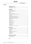
6.3
Setup and function
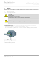
Range of transmitting power
The range of transmitting power is, among others, dependent on the buildings infrastructure. Adjust the location
for the flush-mounted access point to the spatial conditions.
As an example for concrete walls, the graphics show the received power in dependence of the transmitting power
and the distance to the flush-mounted WLAN access point.
49 % Sendeleistung
vorne (im Raum)
Meter
hinten (in der Wand)
100 % Sendeleistung
vorne (im Raum)
Meter
hinten (in der Wand)
Fig. 7:
Legend
> –70 dBm
Reception possible
–60 to –70 dBm
Good to medium reception
0 to –60 dBm
Very good to excellent reception
Pos: 23 /#Neustruktur#/Online-Dokumentation (+KNX)/Steuermodule - Online-Dokumentation (--> Für alle Dokumente <--)/++++++++++++ Seitenumbruch ++++++++++++ @ 9\mod_1268898668093_0.docx @ 52149 @ @ 1
Operating Instructions | 1473-1-7965
— 17 —
Operating Instructions
IP-Netzwerktechnik
Installation and electrical
connection
Pos: 24 /#Neustruktur#/Online-Dokumentation (+KNX)/Überschriften (--> Für alle Dokumente <--)/1. Ebene/M - O/Montage und elektrischer Anschluss @ 23\mod_1336477157864_15.docx @ 209033 @ 1 @ 1
7
Installation and electrical connection
Pos: 25 /#Neustruktur#/Online-Dokumentation (+KNX)/Sicherheitshinweise und Hinweise (--> Für alle Dokumente <--)/Warnhinweise/Sicherheit - Niederspannungs- und 230 V-Leitungen @ 23\mod_1336558868201_15.docx @ 209164 @ @ 1
Warning
Electric voltage!
Risk of death due to electrical voltage of 230 V during short-circuit in the low-voltage line.
– Low-voltage and 230 V lines must not be installed together in a flush-mounted socket!
Pos: 26 /#Neustruktur#/Online-Dokumentation (+KNX)/Sicherheitshinweise und Hinweise (--> Für alle Dokumente <--)/Warnhinweise/Sicherheit - Fachkenntnisse @ 23\mod_1336559183027_15.docx @ 209179 @ 2 @ 1
7.1
Requirements for the electrician
Warning
Electric voltage!
Install the device only if you have the necessary electrical engineering knowledge and experience.
•
Incorrect installation endangers your life and that of the user of the electrical system.
•
Incorrect installation can cause serious damage to property, e.g. due to fire.
The minimum necessary expert knowledge and requirements for the installation are as follows:
•
Apply the "five safety rules" (DIN VDE 0105, EN 50110):
1. Disconnect from power;
2. Secure against being re-connected;
3. Ensure there is no voltage;
4. Connect to earth and short-circuit;
5. Cover or barricade adjacent live parts.
•
Use suitable personal protective clothing.
•
Use only suitable tools and measuring devices.
•
Check the supply network type (TN system, IT system, TT system) to secure the following
power supply conditions (classic connection to ground, protective earthing, necessary
additional measures, etc.).
Pos: 27 /#Neustruktur#/Online-Dokumentation (+KNX)/Steuermodule - Online-Dokumentation (--> Für alle Dokumente <--)/++++++++++++ Seitenumbruch ++++++++++++ @ 9\mod_1268898668093_0.docx @ 52149 @ @ 1
Operating Instructions | 1473-1-7965
— 18 —
Operating Instructions
IP-Netzwerktechnik
Installation and electrical
connection
Pos: 28 /#Neustruktur#/Online-Dokumentation (+KNX)/Überschriften (--> Für alle Dokumente <--)/2. Ebene/M - O/Montage @ 18\mod_1302615960458_15.docx @ 103424 @ 2 @ 1
7.2
Mounting
Pos: 29 /#Neustruktur#/Online-Dokumentation (+KNX)/Montage/alle Geräte/Montage - UP-, AP- und Hohlwanddosen @ 36\mod_1364194901475_15.docx @ 289292 @ @ 1
The device must only be installed in commercially available deep flush-mounted and surface-mounted wall boxes.
Pos: 30 /#Neustruktur#/Online-Dokumentation (+KNX)/Überschriften (--> Für alle Dokumente <--)/2. Ebene/A - F/Elektrischer Anschluss @ 21\mod_1328177051724_15.docx @ 138042 @ 2 @ 1
7.3
7.3.1
Electrical connection
Connecting mains power
Pos: 31 /#Neustruktur#/Online-Dokumentation (+KNX)/Anschluss/Sonstige Bereiche/Anschluss - 8186-31 -- BJE @ 36\mod_1364195245401_15.docx @ 289308 @ 23 @ 1
Warning
Electric voltage!
Risk of death due to electrical voltage.
First disconnect the mains power before starting any installation work!
Caution
Work on the supply system must only be performed by authorised and qualified electricians!
Connecting the mains power.
•
To avoid influencing the network, disconnect the power supply of active components as well as data
transmission devices (PC, etc) from those of other consumers (e.g. radio).
•
Use line circuit breakers or protectors and, if necessary, independent overvoltage protection (C-arrester).
Fig. 8:
Connecting the mains power
* Line circuit breakers or protectors.
Operating Instructions | 1473-1-7965
— 19 —
Operating Instructions
IP-Netzwerktechnik
7.3.2
1.
2.
3.
4.
5.
Installation and electrical
connection
Connecting the network cable
Pull the cable into the flush-mounted wall box from the top.
Use only device connecting boxes!
Shorten the cable so that it projects 90 mm into the box.
Strip approx. 80 mm of the cable.
Insert the flush-mounted WLAN access point into the box.
Pull off the 5-pole screw terminal box.
– Attach the wires according to the colour code.
Fig. 9:
Terminals
6
3
2
1
Screen
Orange
White
green
White
Screw terminal box
Colour code
Terminal
6 3 2 1
Assignment
Fig. 10: Colour code
Observe the following points:
Maintain the pairs screen and the twist of the pairs as long as possible.
– Twist the entire screen.
– If necessary, use a 1 mm wire end sleeve.
Adhere to the assignment in the patch bay and on the box.
6.
7.
Attach the terminal block to the screw terminal.
Check the installation by means of the LEDs (see chapter "Meaning of the LEDs" on page 39) and install the
cover.
The device is now ready for operation with the factory settings.
Pos: 33 /#Neustruktur#/Online-Dokumentation (+KNX)/Steuermodule - Online-Dokumentation (--> Für alle Dokumente <--)/++++++++++++ Seitenumbruch ++++++++++++ @ 9\mod_1268898668093_0.docx @ 52149 @ @ 1
Operating Instructions | 1473-1-7965
— 20 —
Operating Instructions
IP-Netzwerktechnik
Commissioning
Pos: 34 /#Neustruktur#/Online-Dokumentation (+KNX)/Überschriften (--> Für alle Dokumente <--)/1. Ebene/G - L/Inbetriebnahme @ 11\mod_1279185496977_15.docx @ 83035 @ 2 @ 1
8
Commissioning
Pos: 35 /#Neustruktur#/Online-Dokumentation (+KNX)/Inbetriebnahme/Sonstige Bereiche/Inbetriebnahme - 8186-31 -- BJE @ 38\mod_1386234277190_15.docx @ 300818 @ 2 @ 1
8.1
Initial connection
We recommend that you establish the initial connection to the flush-mounted WLAN access point via the RJ45
socket.
•
Connection via the RJ45 socket
To establish the connection via the RJ45 socket, connect your PC to the flush-mounted WLAN access point via a
network cable.
Make the following TCP/IP settings on the network adapter of the configuration PC (or tablet computers or
Smartphones):
TCP/IP-Einstellungen vor:
–
Use the static IP address, e.g. 192.168.55.x, here x must be between 2 and 255.
Subnet mask 255.255.0.0
The flush-mounted WLAN access point can now be reached with a Web browser via address http://192.168.55.1.
•
Connection via WLAN
To establish the connection via WLAN, select the network with the SSID "BJE WLAN AP". The WPA2 key is
"PleaseChange"; we recommend changing this as soon as possible (see chapter "Interface configuration – WLAN
encryption" on page 34).
Make the following TCP/IP settings on the network adapter of the configuration PC (or tablet computers or
Smartphones):
– Use the static IP address, e.g. 192.168.55.x, here x must be between 2 and 255.
Subnet mask 255.255.0.0
The flush-mounted WLAN access point can now be reached with a Web browser via address http://192.168.55.1.
•
Configuration via backward LAN interface
If you wish to configure the flush-mounted WLAN access point via the backward LAN interface, the the subnet
mask 255.255.0.0 must be set on the router and on the configuration PC.
The flush-mounted WLAN access point can now be reached in your network via address http://192.168.55.1.
Pos: 37 /#Neustruktur#/Online-Dokumentation (+KNX)/Steuermodule - Online-Dokumentation (--> Für alle Dokumente <--)/++++++++++++ Seitenumbruch ++++++++++++ @ 9\mod_1268898668093_0.docx @ 52149 @ @ 1
Operating Instructions | 1473-1-7965
— 21 —
Operating Instructions
IP-Netzwerktechnik
Commissioning
Pos: 38 /#Neustruktur#/Online-Dokumentation (+KNX)/Inbetriebnahme/Sonstige Bereiche/Konfiguration - 8186-31xxx -- BJE @ 38\mod_1386236885061_15.docx @ 300915 @ 22333332323233233333323443323444 @ 1
8.2
Configuration
8.2.1
General
You can configure the flush-mounted WLAN access point via the Web interface and adjust it to your requirements.
Aside from the change of password (see chapter "Password setting" on page 23), also the key in the interface
configuration of the WLAN network (see chapter "Network – WLAN settings – Device configuration - General
settings" on page 31) should be changed.
Additionally, you should carry out an adjustment to your network and enter the gateway and the DNS server of
your router for access to the Internet (see chapter "Network IP settings" on page 27.
Note
Please note that before exiting an application page the changed settings must be saved via button
"Save & apply". Otherwise the changes will not be taken over by the flush-mounted WLAN access
point.
After making changes to the settings of the IP address, to the SSID or the WLAN encryption, the
connection between the PC and the flush-mounted WLAN access point may be cut and must be
reestablished by the PC.
Operating Instructions | 1473-1-7965
— 22 —
Operating Instructions
IP-Netzwerktechnik
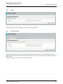
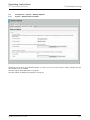
8.2.2
Commissioning
Logon
Fig. 11:
Enter the password ("admin" at the point of delivery) and log yourself in.
8.2.3
Password setting
Fig. 12:
Via menu "System/Administration" you reach the password setting of the flush-mounted WLAN access point.
Raise the access protection by setting an individual password. You can make the password visible by clicking the
green arrows.
Confirm the password and save it under "Save and apply".
Operating Instructions | 1473-1-7965
— 23 —
Operating Instructions
IP-Netzwerktechnik
8.3
8.3.1
Commissioning
Configuration – System – General
System settings
The system settings apply to all operating modes and can be changed in menu "System".
8.3.2
General system settings
To recognize the flush-mounted WLAN access point in your network, enter an individual, clear name under
"Hostname" ("BJE-WLAN-AP“ at the point of delivery). The name must start with a letter and must not contain
spaces. Invalid entries are marked in red. The changes are taken over with "Save and apply".
A restart must be carried out after the hostname has been changed. Click "Reboot" and in the window that opens
click "Perform reboot".
The restart takes approximately one minute.
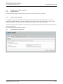
8.4
System/Status configuration
Fig. 13:
Operating Instructions | 1473-1-7965
— 24 —
Operating Instructions
IP-Netzwerktechnik
8.4.1
Commissioning
System language
Fig. 14:
The control interface can be displayed in German or English.
The settings are taken over with "Save & apply".
Operating Instructions | 1473-1-7965
— 25 —
Operating Instructions
IP-Netzwerktechnik
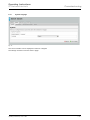
8.5
8.5.1
Commissioning
Status configuration
Status information
Fig. 15:
Under "Status", the current system values and the devices that are connect to the flush-mounted WLAN access
point are displayed. This makes information about the channel and logged-in stations, for example, available for
the configuration. If several stations are logged in, the flush-mounted WLAN access point automatically selects
the one with the strongest signal. To ensure safe data transmission the received power should not drop below
20%.
Aside from the access point modell, also the Firmware version can be read off here.
Operating Instructions | 1473-1-7965
— 26 —
Operating Instructions
IP-Netzwerktechnik
8.6
Commissioning
Network configuration
The operating mode and additional aspects of configuration are set in register "Network" under "IP-Configuration"
and WLAN".
You can select between the three operating modes Access point (state at delivery), Access point (WDS/Repeater)
and Client (WDS) (see chapter "Types of functions" on page 8).
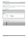
8.6.1
Network IP settings
Fig. 16:
In this menu you receive the status information about the LAN settings of your flush-mounted WLAN access point.
Displayed are running time, MAC address, sending/receiving rate and the IP address. The icons in the left of the
field have the following meaning:
Interface: network cable
Interface: front connection
Interface: radio control
Operating Instructions | 1473-1-7965
— 27 —
Operating Instructions
IP-Netzwerktechnik
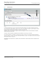
8.6.2
Commissioning
Network - IP settings - Settings
Fig. 17:
Aside from the status information (see chapter "Network IP settings" on page 27), here you can select the
protocol (static address or DHCP client), change the IP address and network mask of your flush-mounted WLAN
access point, and enter the gateway address and DNS server of your router. By clicking the icon (1), you can add
further DNS servers.
Operating Instructions | 1473-1-7965
— 28 —
Operating Instructions
IP-Netzwerktechnik
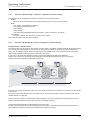
8.7
Commissioning
WLAN network
Fig. 18:
In the WLAN status area you get an overview about the WLAN settings of your flush-mounted WLAN access
point. Displayed are radio standard, channel, bit rate, SSID, mode, BSSD, encryption, signal strength in percent,
logged-in stations with SSID, MAC address, IP address, signal and noise.
Via button "Scan" (1) an overview of adjacent networks is displayed. If there are several networks, a different
channel may have to be chosen.
Via button "Add" and "Delete" (2) additional network interfaces can be set up or removed.
Two network interfaces, for example, are required in the types of functions to increase the WLAN transmission
range (see chapter "Increase in the range of WLAN (with WDS)" on page 11 and chapter "Increase in the range of
WLAN (without WDS)" on page 13).
The settings for the relayd function / repeater mode are described in chapter "Relayd function / Repeater mode"
on page 32.
Operating Instructions | 1473-1-7965
— 29 —
Operating Instructions
IP-Netzwerktechnik
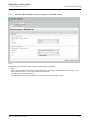
Commissioning
Fig. 19:
Operating Instructions | 1473-1-7965
— 30 —
Operating Instructions
IP-Netzwerktechnik
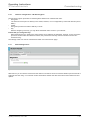
8.7.1
Commissioning
Network - WLAN settings
For WLAN settings a distinction is made between device configuration and interface configuration.
8.7.2
Network – WLAN settings – Device configuration - General settings
Fig. 20:
The following settings are possible aside from the status display:
•
Activating/deactivating WLAN
You can deactivate the WLAN if it not required, to prevent radiation and to save energy. The other two
interfaces remain available. You can also switchover via UDP (see chapter "Controlling the flush-mounted
WLAN access point via UDP" on page 38).
•
Channel
The frequency range of adjacent channels superimpose on each other. That is why the channel should be
selected in such a way that the frequencies of other radio devices in the vicinity do not overlap (e.g. radio
microwave devices in the area of channel 9 and 10). In Germany, 13 channels are permitted, in the USA,
for example, only 11. In order not to restrict the selection of devices, we recommend the use of only
channels 1 to 11.
•
Transmitting power
– By changing the transmitting power the transmission range of the flush-mounted WLAN access point can
be adapted. It should be kept as small as possible in the application range.
Operating Instructions | 1473-1-7965
— 31 —
Operating Instructions
IP-Netzwerktechnik
8.7.3
Commissioning
Network – WLAN settings – Interface configuration - General settings
The settings that are possible in the interface configuration are network-specific:
•
ESSID
Network name with which the flush-mounted WLAN access point is to be connected
•
Mode
– Four modes are available for selection:
The operating mode access point,
Client (WDS),
Client (Relayd)
and access point (WDS/Repeater) (see chapter "Types of functions" on page 8)
•
Hide ESSID
Prevents unauthorized devices from seeing your network
The entries are taken over with "Save & apply".
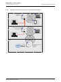
8.7.4
Network – WLAN settings – Device configuration - General settings
Relayd function / Repeater mode
The relayd function is the basis for the repeater function. Here an available, possibly weak WLAN signal is picked
up, boosted and re-transmitted as access point on the mounting position of the flush-mounted WLAN access
point. This, for example, allows WLAN connections on an available router to be 'extended' and/or made more
operationally reliable. Please note that the maximum data rates
in the types of functions with repeater function are fundamentally halved with each additional
repeat. This is due to the general physical principles of the WLAN transmission and not to any special
characteristic of the flush-mounted WLAN access point.
Router
Internet
WLAN access point, FM
1 x repeated (50 %)
WLAN access point, FM
2 x repeated (25 %)
possible, not recommendable
Fig. 21:
The types of functions as repeater and access point require appropriate configuration in the flush-mounted WLAN
access point.
Since this involves two different type of WLAN functions, two network interfaces need to be set up (see chapter
"WLAN network" on page 29).
The first network interface is configured as "Client (Relayd)". Here the IP address of the Relayd client must lie
within the identical address range of the router (or the amplifying device).
The second network interface is parameterized as access point.
Via this network interface during WLAN operation the connection of mobile data transmission units is made, or
also additional repeaters that were set up identically in previous processes.
Operating Instructions | 1473-1-7965
— 32 —
Operating Instructions
IP-Netzwerktechnik
8.7.5
Commissioning
Network – WLAN settings – Device configuration - Extended settings
Fig. 22:
Further settings can be made under the device and interface configuration.
•
Mode
At the point of delivery the devices can log themselves in according to standard IEEE-802.11-b/g/n. If you
wish to limit the access, you can set special radio standards
•
HT mode (only for mode 802.11g+n)
In n-Standard, HT 20/40 can be selected. Test the band width with the best result.
Operating Instructions | 1473-1-7965
— 33 —
Operating Instructions
IP-Netzwerktechnik
8.7.6
Commissioning
Interface configuration – WLAN encryption
The WLAN encryption protects the network against attacks from unauthorized users.
•
Encryption
The mode set at the point of delivery is the safest; however, it is not supported by some older devices (avoid
WEP!)
•
Cipher
Encryption procedure at state of delivery is "auto"
•
Key
With the assigning of the key you only allow authorized users access to your network.
Ensure that you change the key!
When selecting the key, observe the same criteria as for selecting the password; however, for the encryption
procedure such as WPA and WPA2 for WLAN, the password for security reasons should be at least 20
characters long.
The settings made can now be confirmed and taken over with "Save & apply".
8.7.7
Network diagnostics
Fig. 23:
With this tool you can test the network and the Internet connections. Enter an Internet address (can be internal or
external) and click "Ping". You will then receive information whether the data were sent and the distant end has
replied.
Operating Instructions | 1473-1-7965
— 34 —
Operating Instructions
IP-Netzwerktechnik
8.8
8.8.1
Commissioning
Configuration – System – Backups/Updates
System – Backup/Software-Update
Fig. 24:
As backup you can store your individual settings on a PC or you can carry out a reset to factory settings. Also the
new Firmware can be installed.
See also chapter "Backup/Restore" on page 36.
See also chapter "Installing new Firmware" on page 36.
Operating Instructions | 1473-1-7965
— 35 —
Operating Instructions
IP-Netzwerktechnik
8.8.1.1
Commissioning
Backup/Restore
For the backup, select a folder on your PC in which you save the current settings. Click "Generate archive". Click
"Upload archive" to restore the status at the point of delivery. If, for example, you wish to install several flushmounted WLAN access points with identical configuration, you can save the settings of a device as backup and
load them into additional devices.
8.8.1.2
Installing new Firmware
New Firmware can be downloaded from our electronic catalogue (www.busch-jaeger-katalog.de). Proceed as
follows::
1. Save the file on your PC.
2. If you wish to keep your current settings, confirm this.
3. Select the stored file.
4. Click "Flash image".
Operating Instructions | 1473-1-7965
— 36 —
Operating Instructions
IP-Netzwerktechnik
8.8.2
Commissioning
Reboot
Fig. 25:
With a restart you reset the system or take over the settings you made.
8.8.3
Log off
With "Logout" you exit the control interface of the flush-mounted WLAN access point. However, first you must
save the settings made. To make further changes, you must log on again with your password.
8.9
8.9.1
Configuration – Expert information
Expert diagram
This menu makes detailed information available about the current data transmissions in the LAN and WLAN area,
for use as an analysis tool.
8.9.1.1
LAN1
With this diagram you can check whether a LAN connection exists and the data rates that are transmitted in and
out within a period of 3 minutes.
8.9.1.2
WLAN
The WLAN diagram provides information about the quality of transmission with regard to signal, noise and the
data rate.
Pos: 40 /#Neustruktur#/Online-Dokumentation (+KNX)/Steuermodule - Online-Dokumentation (--> Für alle Dokumente <--)/++++++++++++ Seitenumbruch ++++++++++++ @ 9\mod_1268898668093_0.docx @ 52149 @ @ 1
Operating Instructions | 1473-1-7965
— 37 —
Operating Instructions
IP-Netzwerktechnik
Operation
Pos: 41 /#Neustruktur#/Online-Dokumentation (+KNX)/Überschriften (--> Für alle Dokumente <--)/1. Ebene/A - F/Bedienung @ 11\mod_1279185541649_15.docx @ 83043 @ 2 @ 1
9
Operation
Pos: 42 /#Neustruktur#/Online-Dokumentation (+KNX)/Bedienung/Sonstige Bereiche/Bedienung - 8186-31 -- BJE @ 38\mod_1386234334359_15.docx @ 300850 @ 22233 @ 1
9.1
Controlling the flush-mounted WLAN access point via UDP
The WLAN interface of the device can be activated and deactivated via UDP command. Activate the UDP function
by entering the desired port under menu "System". No port is set at the point of delivery.
Then confirm the entry by clicking button "Save & apply".
Restart!
To take over the UDP ports entered, a restart of the flush-mounted WLAN access point is
absolutely necessary. Click "Reboot" and in the window that opens click "Perform reboot".
The restart takes approximately one minute.
– The UDP function is then available.
UDP commands
Commands
Meaning
WLAN ON
Activating the WLAN interface
WLAN OFF
Deactivating the WLAN interface
WLAN ?
Enquiry of status
Observe capitalization and spaces during the entry.
The flush-mounted WLAN access point confirms a sent UDP command with a reply of the current status.
Operating Instructions | 1473-1-7965
— 38 —
Operating Instructions
IP-Netzwerktechnik
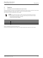
9.2
Operation
Meaning of the LEDs
For a detailed fault analysis and for commissioning, also the status of the LEDs that can be seen on the upper
module of the flush-mounted WLAN access point when the cover is removed, can be used. They indicate the
activity at the respective ports - screw terminal and UAE socket.
No.
Function
1
Link/Act
2
Link/Act
1
External Ethernet Port (screw terminal)
Local Ethernet Port (UAE socket)
2
Fig. 26:
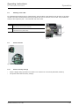
9.3
Reset functions
Detail X
Fig. 27:
9.3.1
•
•
Reset to factory settings
Create a bridge during operation for at least 5 to a maximum of 30 seconds (illustration, Detail X)
The system starts with the factory settings.
Operating Instructions | 1473-1-7965
— 39 —
Operating Instructions
IP-Netzwerktechnik
9.3.2
Operation
Full reset
If you do not have access to the flush-mounted WLAN access point, you can reset the device fully. After this a
firmware must be installed in the flush-mounted WLAN access point.
1.
2.
3.
4.
5
6
De-energize the flush-mounted WLAN access point.
Create a bridge (illustration, Detail X)
Reactivate the power supply.
Wait 5 seconds.
Connect a PC to the flush-mounted WLAN access point via the RJ45 socket.
Make the following TCP/IP setting on the network adapter of the PC:
–
–
-
Use the static IP address: 192.168.1.2
Select "Windows - Start - Execute", and there enter "cmd" and confirm with "OK".
Enter "tftp -i 192.168.1.1 put <File name>", replace the <File name> with the file name and path of the
current Firmware file (see chapter "Installing new Firmware" on page 36). New Firmware can be
downloaded from our electronic catalogue (www.busch-jaeger-katalog.de).
The system sends a feedback signal about the successful data transmission. After a restart the flush-mounted
WLAN access point is then again available with the factory settings.
Meaning of the entry:
C:\
Change to the root directory
tftp
Start TFTP client (available in the operating system)
-i
Binary data transmitted
192.168.1.1
Address of the TFTP server in the flush-mounted WLAN access point
put
Transmit data
Pos: 44 /#Neustruktur#/Online-Dokumentation (+KNX)/Steuermodule - Online-Dokumentation (--> Für alle Dokumente <--)/++++++++++++ Seitenumbruch ++++++++++++ @ 9\mod_1268898668093_0.docx @ 52149 @ @ 1
Operating Instructions | 1473-1-7965
— 40 —
Operating Instructions
IP-Netzwerktechnik
Fault rectification
Pos: 45 /#Neustruktur#/Online-Dokumentation (+KNX)/Überschriften (--> Für alle Dokumente <--)/1. Ebene/S - T/Störungsbeseitigung @ 18\mod_1308568208399_15.docx @ 107037 @ 2 @ 1
10
Fault rectification
Pos: 46 /#Neustruktur#/Online-Dokumentation (+KNX)/Störungsbeseitigung/Sonstige Bereiche/Stoerungsbeseitigung - 8186-31 @ 38\mod_1386238116606_15.docx @ 300947 @ @ 1
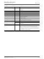
Cause
Action
LEDs do not light up
The flush-mounted WLAN access point has no supply voltage.
Switch on the supply voltage.
No connection to the WLAN base station
The flush-mounted WLAN access point is outside the range of the
Reduce the distance between the devices.
base station.
The WLAN function of your flush-mounted WLAN access point has
Activate the WLAN function.
been deactivated.
A different WLAN radio network causes interference.
Set a different channel or set the channel on "Auto".
The encryption of your flush-mounted WLAN access point is set on
Set the encryption on WPA/WPA2 in the user interface.
"WEP" or is set on "Unencrypted".
The ESSID is set on "hidden".
The ESSID must be set on "visible" for the connection with WEP.
Set the ESSID on "visible". After the connection has been
established, the ESSID can be set back on "hidden".
A different encryption procedure has been set on the flush-
Set the same encryption procedure on the PC that is set on
mounted WLAN access point than on the PC.
WLAN access point.
No WLAN connection to the PC
The WLAN adapter of the PC is not ready.
Check whether the WLAN adapter has been activated; on some
devices it must be activated with a switch.
The PC is outside the range of the flush-mounted WLAN access
Reduce the distance between the PC and the flush-mounted
point.
WLAN access point.
A different encryption procedure has been set on the flush-
Set the same encryption procedure on the PC that is set on
mounted WLAN access point than on the PC.
WLAN access point.
No access to the devices in the network possible
A firewall is operating on the devices.
Allow the firewall access to the network.
Wrong address range / wrong network mask
Check whether the addresses have been set correctly.
The flush-mounted WLAN access point cannot be located under the IP address
The DHCP client has been activated.
Try to locate the device via the WLAN function.
The plain text display for password and key does not function
You are using Internet Explorer 9.
Go to the compatibility view and remove all activations under
Extras/Settings.
The diagram is not displayed.
You are using Internet Explorer 7 or 8.
Install an SVG plug-in (e.g. from Adobe at
http://www.adobe.com/devnet/svg/adobe-svg-viewer-downloadarea.html).
You are using Internet Explorer 9.
Go to the compatibility view and remove all activations under
Extras/Settings.
Pos: 47 /#Neustruktur#/Online-Dokumentation (+KNX)/Steuermodule - Online-Dokumentation (--> Für alle Dokumente <--)/++++++++++++ Seitenumbruch ++++++++++++ @ 9\mod_1268898668093_0.docx @ 52149 @ @ 1
Operating Instructions | 1473-1-7965
— 41 —
Operating Instructions
IP-Netzwerktechnik
Glossary
Pos: 48 /#Neustruktur#/Online-Dokumentation (+KNX)/Überschriften (--> Für alle Dokumente <--)/1. Ebene/G - L/Glossar @ 32\mod_1358157269639_15.docx @ 263499 @ 2 @ 1
11
Glossary
Pos: 49 /#Neustruktur#/Online-Dokumentation (+KNX)/Glossar/Sonstige Bereiche/Glossar - 8186-31 @ 38\mod_1386238187254_15.docx @ 300963 @ @ 1
Meaning
Abbreviation
Function
Access point
AP
Base station, interface for wireless communication, terminal devices are
logged via WLAN into the access point which is connected to the network
via cable, comparable with bridges or switches, layer 2 based
Adapter
Advanced Encryption Standard
Connects a cabled communication device with an AP via WLAN
AES
Freely available encryption algorithm with 128, 192 or 256 bit key length
and 128 bit block size
Basic Service Set
BSS
Basic Service Set Identifier
BSSID
The result of synchronization of relevant parameters with several devices
Corresponds either to the MAC address of the AP or is randomly generated
and clearly describes each BSS
Cipher
Operating mode in which texts that are longer than the block cipher length
can be encrypted (e.g. AES)
Client
Connects a cabled communication device with an AP via WLAN, also
termed repeater and WLAN adapter
DNS Server
Domain Name System
Computer (Server) that carries out name resolution
DNS
Forms the name resolution, i.e. conversion of a hostname into the relevant
IP address
Extended Service Set
ESS
Coupling several WLAN radio cells into a larger one
Extended Service Set Identifier
ESSID
Connecting of several APs to a network requires the same SSID, which is
High Throughput
HT mode
Larger band width in HT-40 mode and with it higher speeds are possible.
in this case called ESSID
Transmission range is reduced, speed advantage only partly realistic
(IEEE-802.11-n devices are required, provided the connection is optimal).
Hostname
Independent Basic Service Set
Name of AP
IBSS
IPv4 address
BSS is a closed network without connection to another network
Fourth version of the Internet Protocol, 32.bit address in four blocks of
decimal style with 8 bits each, one value range from 0-255 and separated
by a point (xxx.xxx.xxx.xxx)
IPv4 gateway
Links networks of different protocols, specifies the path to the Internet
IPv4 netmask
Division between the network part and address part of the IP address,
computers are in the same network if the address part is the same (the bits
of the netmask that are equal to "1")
Channel
The frequency range available in the 2.4 GHz range is for better utilization
divided into 14 channels, the first 13 being available in Europe.
Local Area Network
LAN
Local network with maximum extension of 500 m, mainly in the home and
up to small companies
Operating Instructions | 1473-1-7965
— 42 —
Operating Instructions
IP-Netzwerktechnik
Glossary
Mode
Setup and function on page 8
Port
Part of a network address to assign data packets between client and
server. With UDP the port number of the service that is to receive the data
is also sent
Protocol
Software agreement for data transmission
Repeater
Signal amplifier that increases the transmission range
Roaming
Taking the WLAN connection along from one AP to the next
Key / password
Access protection
Transmitting power
Service Set Identifier
Delivered power of the AP mostly indicated in dBm
SSID
Freely selectable name of a WLAN up to 32 character long, setting in the
AP and all connected clients
Temporal Key Integrity Protocol
TKIP
Security protocol in the WLAN or other radio networks is based on the
IEEE-802.11 standard
User Datagram Protocol
UDP
Simple, wireless network protocol for transmitting data. Port are used for
assigning the data to the correct application.
Encryption
Wi-Fi Protected Access
Serves for the security of data transmission
WPA
WPA2
WLAN encryption algorithm
Successor of WPA and based on AES according to WLAN standards IEEE
802.11 a,b,g,n
Wired Equivalent Privacy
WEP
Wireless Distribution System
WDS
WLAN encryption algorithm
Procedure for addressing data frames, setup of a radio network with
several APs, WDS both with a WLAN interface (Single-Radio-WDS,
connection to the AP and client), as well as with several Dual-Radio-WDS,
one interface to the AP and another one to the client, implemented on the
AP, differentiation in bridging ( 2 WLAN bridges connected) and repeating
mode (several APs connected via WDS).
Wireless Local Area Network
WLAN
Like WLAN, but wireless
=== Ende der Liste für Textmarke Content ===
Operating Instructions | 1473-1-7965
— 43 —
Operating Instructions
IP-Netzwerktechnik
A member of the ABB Group
Notice
We reserve the right to at all times make
Busch-Jaeger Elektro GmbH
PO box
58505 Lüdenscheid
Freisenbergstraße 2
58513 Lüdenscheid
Germany
www.BUSCH-JAEGER.de
[email protected]
Central sales service:
Phone:
+49 (0) 2351 956-1600
Fax:
+49 (0) 2351 956-1700
technical changes as well as changes to the
contents of this document without prior notice.
The detailed specifications agreed to at the time
of ordering apply to all orders. ABB accepts no
responsibility for possible errors or
incompleteness in this document.
We reserve all rights to this document and the
topics and illustrations contained therein. The
document and its contents, or extracts thereof,
must not be reproduced, transmitted or reused by
third parties without prior written consent by ABB.
Copyright© 2013 Busch-Jaeger Elektro GmbH
All rights reserved
=== Ende der Liste für Textmarke Backcover ===
1473-1-7965 | 04.04.2014
Pos: 51 /#Neustruktur#/Online-Dokumentation (+KNX)/Rückseiten (--> Für alle Dokumente <--)/Rückseite - BJE-Variante @ 32\mod_1357201421897_15.docx @ 262132 @ @ 1