1
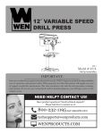
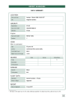
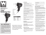
12-1/2 IN.
THICKNESS PLANER
Model # 6550
bit.ly/wenvideo
IMPORTANT:
Your new tool has been engineered and manufactured to WEN’s highest standards for dependability,
ease of operation, and operator safety. When properly cared for, this product will supply you years
of rugged, trouble-free performance. Pay close attention to the rules for safe operation, warnings,
and cautions. If you use your tool properly and for intended purpose, you will enjoy years of safe,
reliable service.
NEED HELP? CONTACT US!
Have product questions? Need technical support?
Please feel free to contact us at:
800-232-1195 (M-F 8AM-5PM CST)
[email protected]
WENPRODUCTS.COM
TABLE OF CONTENTS
2
3
4
5
7
7
9
12
15
18
Technical Data
General Safety Rules
Specific Safety Rules For Planer
Electrical Information
Know Your Planer
Assembly and Adjustments
Operation
Maintenance
Exploded View and Parts List
Warranty
TECHNICAL DATA
Model Number:
Motor:
Cutterhead Speed:
Cuts Per Minute:
Feed rate:
Maximum Depth of Cut:
Table Size:
Extension Table Size:
Base Size:
Workpiece Width (max.):
Workpiece Thickness (max.):
Weight:
2
6550
120 V, 60 Hz, 12A
9400 RPM
18800
26 FPM
3/32˝
12-1/2 x 9-3/8˝
12-1/2 x 6-3/4˝
21 x 12-1/2˝
12-1/2˝
6˝
67 lbs
GENERAL SAFETY RULES
Safety is a combination of common sense, staying alert and knowing how your item works. SAVE THESE
SAFETY INSTRUCTIONS.
WARNING: To avoid mistakes and serious injury, do not plug in your tool until the following
steps have been read and understood.
1. READ and become familiar with this entire instruction manual. LEARN the tool’s applications, limitations,
and possible hazards.
2. AVOID DANGEROUS CONDITIONS. Do not use power tools in wet or damp areas or expose them to
rain. Keep work areas well lit.
3. DO NOT use power tools in the presence of flammable liquids or gases.
4. ALWAYS keep your work area clean, uncluttered, and well lit. DO NOT work on floor surfaces that are
slippery with sawdust or wax.
5. KEEP BYSTANDERS AT A SAFE DISTANCE from the work area, especially when the tool is operating.
NEVER allow children or pets near the tool.
6. DO NOT FORCE THE TOOL to do a job for which it was not designed.
7. DRESS FOR SAFETY. Do not wear loose clothing, gloves, neckties, or jewelry (rings, watches, etc.) when
operating the tool. Inappropriate clothing and items can get caught in moving parts and draw you in. ALWAYS
wear non-slip footwear and tie back long hair.
8. WEAR A FACE MASK OR DUST MASK to fight the dust produced by sawing operations.
WARNING: Dust generated from certain materials can be hazardous to your health. Always
operate the tool in a well-ventilated area and provide for proper dust removal. Use dust collection
systems whenever possible.
9. ALWAYS remove the power cord plug from the electrical outlet when making adjustments, changing parts,
cleaning, or working on the tool.
10. KEEP GUARDS IN PLACE AND IN WORKING ORDER.
11. AVOID ACCIDENTAL START-UPS. Make sure the power switch is in the OFF position before plugging
in the power cord.
12. REMOVE ADJUSTMENT TOOLS. Always make sure all adjustment tools are removed from the saw
before turning it on.
13. NEVER LEAVE A RUNNING TOOL UNATTENDED. Turn the power switch to OFF. Do not leave
the tool until it has come to a complete stop.
3
GENERAL SAFETY RULES
14. NEVER STAND ON A TOOL. Serious injury could result if the tool tips or is accidentally hit. DO NOT store
anything above or near the tool.
15. DO NOT OVERREACH. Keep proper footing and balance at all times. Wear oil-resistant rubber-soled footwear. Keep the floor clear of oil, scrap, and other debris.
16. MAINTAIN TOOLS PROPERLY. ALWAYS keep tools clean and in good working order. Follow instructions for lubricating and changing accessories.
17. CHECK FOR DAMAGED PARTS. Check for alignment of moving parts, jamming, breakage, improper
mounting, or any other conditions that may affect the tool’s operation. Any part that is damaged should be properly
repaired or replaced before use.
18. MAKE THE WORKSHOP CHILDPROOF. Use padlocks and master switches and ALWAYS remove starter keys.
19. DO NOT operate the tool if you are under the influence of drugs, alcohol, or medication that may affect your
ability to properly use the tool.
20. USE SAFETY GOGGLES AT ALL TIMES that comply with ANSI Z87.1. Normal safety glasses only have
impact resistant lenses and are not designed for safety. Wear a face or dust mask when working in a dusty environment. Use ear protection such as plugs or muffs during extended periods of operation.
SPECIFIC RULES FOR THE PLANER
WARNING: For your own safety, read all of the instructions and precautions before operating tool.
WARNING: Operation of any power tool can result in foreign objects being thrown into eyes which
can result in severe eye damage. Always wear safety goggles complying with United States ANSI Z87.1
(shown on package) before commencing power tool operation.
CAUTION: Always observe the following safety precautions:
1. Whenever adjusting or replacing any parts on planer, turn switch OFF and remove plug from power source.
2 Make sure all guards are properly attached and securely fastened.
3. Make sure all moving parts are free from interference.
4. Always wear eye protection or face shield.
5. Make sure blades are aligned and properly attached to cutterhead.
6. Do not plug in planer unless the switch is in the off position. After turning the switch on, allow the planer to
come to full speed before operating.
4
SPECIFIC RULES FOR THE PLANER
6. Keep hands clear of all moving parts.
7. Do not force cut. Slowing or stalling will overheat motor. Allow automatic feed to function properly.
8. Use quality lumber. Blades last longer and cuts are smoother with good quality wood.
9. Do not plane material shorter than 15”, narrower than 3/4”, wider than 12-1/2” or thinner than 1/2”.
10. Never make planing cut deeper than 3/32".
11. For workpieces longer than 24", use material support stands.
12. Do not back the work towards the infeed side.
13. Take precautions against kickback. Do not permit anyone to stand or cross in line of cutterhead’s rotation.
Kickback or thrown debris will travel in this direction.
14. Turn switch off and disconnect power whenever planer is not in use.
15. Replace knives as they become damaged or dull.
16. Keep planer maintained. Follow maintenance instructions.
ELECTRICAL INFORMATION
GROUNDING INSTRUCTIONS
IN THE EVENT OF A MALFUNCTION OR BREAKDOWN, grounding provides the path of least resistance
for an electric current and reduces the risk of electric shock. This tool is equipped with an electric cord that has an
equipment grounding conductor and a grounding plug. The plug MUST be plugged into a matching outlet that is
properly installed and grounded in accordance with ALL local codes and ordinances.
DO NOT MODIFY THE PLUG PROVIDED. If it will not fit the outlet, have the proper outlet installed by a
licensed electrician.
IMPROPER CONNECTION of the equipment grounding conductor can result in electric shock. The conductor with the green insulation (with or without yellow stripes) is the equipment grounding conductor. If repair or
replacement of the electric cord or plug is necessary, DO NOT connect the equipment grounding conductor to a
live terminal.
CHECK with a licensed electrician or service personnel if you do not completely understand the grounding instructions or whether the tool is properly grounded.
CAUTION: In all cases, make certain the outlet in question is properly grounded. If you are not sure, have a licensed electrician check the outlet.
5
ELECTRICAL INFORMATION
WARNING: This tool is for indoor use only. Do not expose to rain or use in damp locations.
Guidelines for using extension cords
Make sure your extension cord is in good condition. When using an extension cord, be sure to use one heavy
enough to carry the current your product will draw. An undersized cord will cause a drop in line voltage resulting
in loss of power and overheating. The table below shows the correct size to be used according to cord length and
nameplate ampere rating. When in doubt, use a heavier cord. The smaller the gauge number, the heavier the cord.
Make sure your extension cord is properly wired and in good condition. Always replace a damaged extension cord
or have it repaired by a qualified person before using it.
Protect your extension cords from sharp objects, excessive heat and damp/wet areas.
Use a separate electrical circuit for your tools. This circuit must not be less than a #12 wire and should be protected
with a 15 A time-delayed fuse. Before connecting the motor to the power line, make sure the switch is in the OFF
position and the electric current is rated the same as the current stamped on the motor nameplate. Running at a
lower voltage will damage the motor.
WARNING: This tool must be grounded while in use to protect the operator from electric shock.
AMPERAGE
12 A
6
REQUIRED GAUGE FOR EXTENSION CORDS
25 ft.
50 ft.
100 ft.
150 ft.
14 gauge
12 gauge
Not
Recommended
Not
Recommended
KNOW YOUR PLANER
Depth Adjusting Handle
Carrying Handle
Switch
Circuit Breaker
Extension Table
ASSEMBLY AND ADJUSTMENTS
UNPACKING (FIGURE 1)
IMPORTANT: Remove protective paper from the table before operating
the unit.
The planer comes assembled as one unit. Additional parts which need to be
fastened to planer should be located and accounted for before assembling.
A Dust Chute
B Thumb Screw (2)
C T-handle Hex Wrench (on planer)
D Plug
E Magnet (2, on planer)
F Depth adjusting handle
G Bolt with Lock Washer
WARNING: Do not attempt assembly if parts are missing. Use
this manual to order replacement parts.
Figure 1
7
ASSEMBLY AND ADJUSTMENTS
INSTALL DEPTH ADJUSTING HANDLE (FIGURE 2 & 3)
The handle and knob should be installed to top-right of the planer. Insert the handle with the knob onto the
elevation screw’s top. Secure handle with bolt using T-handle wrench provided. Insert plug into handle to cover
bolt.
Figure 2
Figure 3
ATTACH DUST CHUTE (FIGURE 4)
Planer is best used along with a dust collector. Dust chute is
included. The dust chute is mounted to the rollercase using two
thumb screws. The dust chute can be mounted to direct chips to
either side of planer.
After mounting, connect wet/dry vacuum hose to dust chute. Be
sure to turn the vacuum on before operating the planer.
MOUNT PLANER TO WORK SURFACE (Figure 5)
The planer is designed to be portable so it can be moved to a
job site. However, it should always be mounted to a stable, level
bench or table in a place with ample lighting and correct power
supply. Make sure there is plenty of room for moving the workpiece through the entire cut. Neither the operators or the bystanders should have to stand in line with the wood while using the tool.
The base of the planer has four mounting holes. Mount the planer to the workbench or to the tool stand using bolts, flat washers
and hex nuts (not supplied). Figure 5 shows the base dimensions,
mounting holes and required space to allow for table assembly.
Securely mount the planer to the work table by bolting it through
the holes. Make sure the planer does not rock and that the work
table is level.
8
Figure 4
Figure 5
OPERATION
WARNING: Do not connect planer to the power source until all assembly steps have been completed.
The WEN® 12-1/2" Planer planes soft and hardwoods up to 6" thick and 12-1/2" wide. Wood feeds into the twoblade cutterhead by rubber infeed/outfeed rollers. Planer can take cuts up to 3/32" per pass at 26 feet per minute.
ON/OFF SWITCH (FIGURE 6)
The ON/OFF switch is located on the front of the planer motor. To
turn the planer ON, move the switch to the up position. To turn the
planer OFF, move the switch to the down position.
SWITCH LOCK (FIGURE 7)
Remove the red tab to engage child-safety lock and prevent unwanted
start-ups. To lock the switch:
Turn the switch to OFF position and disconnect planer from power
source. Pull the key out. The switch cannot be turned on with the key
removed. To replace key, slide key into the slot on switch until it
snaps.
Figure 6
NOTE: The key can be removed from the switch while in the ON
position. This allows for the device to be turned off but still prevents it from being turned back on.
CIRCUIT BREAKER (FIGURE 6)
The planer is equipped with a motor protection device-circuit
Figure 7
breaker. The breaker will automatically shut the planer off when
excessive current is consumed. If the breaker is tripped, turn the planer off and reset the circuit by pressing the
button.
CAUTION: Be sure to turn the planer off prior to resetting the circuit breaker to avoid unintentional start-up of
the planer.
AVOID DAMAGE TO BLADES
Thickness planers are a precision woodworking machine and should be used on quality lumber only. Do not
plane dirty boards; dirt and small stones are abrasive and will wear out blade.
REMOVE NAILS AND STAPLES. Use planer to cut wood only.
Avoid knots. Heavily cross-grained wood makes knots hard. Knots can come loose and jam blade.
WARNING: Any article that encounters planer blades may be forcibly ejected from planer creating risk
of injury. Make sure the wood is free from outside materials before attempting to plane.
9
OPERATION
DEPTH OF CUT (FIGURE 8)
Depth-of-cut is adjusted by raising or lowering the rollercase using handle. Each full rotation of the handle moves the rollercase
1/16". Quality of thickness planing depends on the operator’s
judgement about the depth of cut. Depth of cut depends on the
width, hardness, dampness, grain direction and grain structure
of the wood. Maximum thickness of wood which can be removed in one pass is 3/32” for planing operations on workpieces up to 5” wide. Workpiece must be positioned away from the
center tab on the rollercase to cut 3/32”. Maximum thickness
of wood which can be removed in one pass is 3/32” for planing
operations on workpiece from 5” up to 121/2” wide.
Figure 8
CAUTION: A 3/32” depth-of-cut on hard, softwood 6-12” wide can be made. However, continuous operation at
this set-up can cause premature motor failure.
• For optimum planing performance, the depth of cut should be less than 1/16”. Run the board a few times before adding depth to ensure the best possible cuts.
• Boards should be planed with shallow cuts until the work has a level side (or alternatively the use of a power
jointer can be employed). Once a level surface has been created, flip the lumber and create parallel sides.
• Plane alternate sides until the desired thickness is obtained. When half of the total depth of cut is taken from
each side, the board will have a uniform moisture content. Any additional drying should not cause it to warp.
• Depth of cut should be shallower when work is wider.
• When planing hardwood, take light cuts or plane the wood in thin widths.
• Make a test cut with a test piece and verify the thickness produced.
• Check accuracy of test cut prior to working on finished product.
PREPARE WORK
Thickness planers work best when at least one side of the lumber is flat. Use a surface planer or a jointer to create
a flat surface. Twisted or severely warped boards can jam the planer and should not be used. Rip lumber in half to
reduce magnitude of warp.
Work should be fed into the planer in same direction as the grain of the wood. Sometimes grain will change
directions in middle of board. In such cases, if possible, cut board in middle before planing so grain direction is
correct. NEVER PLANE AGAINST THE GRAIN DIRECTION OF THE WOOD. DO NOT PLANE END
GRAIN, AS THE WOOD COULD SPLINTER OR POSSIBLY EXPLODE.
CAUTION: Do not plane board which is less than 14-1/2" long; force of cut could split board and cause kickback.
10
OPERATION
FEEDING WORK
The planer is supplied with planing blades mounted in the cutterhead and infeed and outfeed rollers adjusted to
the correct height. Planer feed is automatic; it will vary slightly depending on type of wood.
• Feed rate refers to the rate at which the lumber travels through the planer.
• Align the work perpendicular to the rollercase so that the work feeds through the planer straight.
• Raise/lower rollercase to produce the depth of cut desired.
• Stand on the side of the planer with the handle.
• Boards longer than 24" should have additional support from free standing material stands.
• Position the workpiece with the face to be planed on top.
• Turn the planer on.
• Rest the board end on the table and direct the board into the planer.
• Gently slide workpieces into the infeed side of the planer until the infeed roller advances the workpiece.
• Let go of the workpiece and allow automatic feed to advance the workpiece.
• Do not push/pull on workpiece. Move to the rear and receive planed lumber by grasping it in same manner as
it was fed.
CAUTION: To avoid risk of injury due to kickbacks, do not stand directly in line with the front or rear of planer.
• Do not grasp any portion of board which has not gone past the out-feed roller.
• Repeat this operation on all boards which need to be same thickness.
• Planer has return roller on top so assistant can pass work back to operator.
NOTE: Assistant must follow same precautions as operator.
• Surface that the planer will produce will be smoother if shallower depth of cut is used.
AVOIDING SNIPE
• Snipe refers to a depression at either end of board caused by an uneven force on cutterhead when work is entering or leaving planer.
• Snipe will occur when boards are not supported properly or when only one feed roller is in contact with work at
beginning or end of cut.
• To avoid snipe, gently push the board up while feeding the work until the outfeed roller starts advancing it.
• Move to the rear and receive planed board by gently pushing it up when the infeed roller loses contact with the
board.
• When planing more than one board of the same thickness, butt boards together to avoid snipe.
• Snipe is more apparent when deeper cuts are taken. Lower depth helps to avoid snipe.
• Feed the work in the direction of the grain. Work fed against the grain will have chipped, splintered edges.
11
MAINTENANCE
CHECK FOR WORN BLADES
Condition of blades will affect the precision of cuts. Observe the quality of the cut that the planer produces to
check the condition of the blades. Dull blades will tear, rather than sever wood fibers and produce fuzzy appearances. Raised grain will occur when dull blades pound on wood that has varying density. Raised edges will also be
produced where the blades have been nicked. Blades on this planer are reversible and should always be reversed
or replaced as a matched set. Keeping a spare set of blades on hand is recommended.
CHANGING BLADES (FIGURES 9, 10, 11)
WARNING: Always turn the planer OFF and disconnect it from
the power source before starting any maintenance work.
Loosen and remove thumb screws from blade guard on the rear
side of planer. Remove blade guard. Carefully turn cutterhead by
hand towards you until it is stopped by the self-engaging latch.
Loosen and remove six bolts from gib. Remove gib using magnets provided.
Figure 9
NOTE: Magnets can be easily disengaged from gib by tilting
them to left or right.
CAUTION: Blade edges are extremely sharp. Keep fingers away
from blades at all times.
The blade is held in position by two pins. Gently lift the old
blades from the cutterhead using magnets. Do not make contact
with the blade using fingers. Use magnet only.
Reverse or replace blade and carefully position it on the two pins
using magnets. Replace gib and align the holes on the gib with
holes on the blade using magnets.
Figure 10
Secure gib to cutterhead using six bolts removed earlier. Depress
latch to release cutterhead. Release latch when cutterhead can
be turned by hand. Turn cutterhead by hand until it is stopped by
selfengaging latch.
Remove gib and blade as mentioned earlier. Replace with new
blade. Replace gib and secure it as mentioned earlier. Replace
blade guard and secure it using two bolts.
12
Figure 11
MAINTENANCE
BRUSH INSPECTION AND REPLACEMENT
WARNING: Turn planer off and disconnect from power
source before inspecting or replacing brushes.
Brush life depends on amount of load on motor. Regularly
inspect brushes after 100 hours of use. Brushes are located on either
side of planer motor, on both the front and rear side of the planer.
• Loosen brush cap and carefully remove brush from motor.
• Replace brushes if spring is damaged.
• Replace brushes if carbon is worn.
• Tighten brush caps after replacement.
ADJUSTING TABLE LEVEL
Refer to Exploded Views, Figures 13 and 14, pages 15 and 17.
Figure 12
The planer will produce uneven depth of cut (tapered cut) if the rollercase (26 - Figure 14) is not parallel with the
base (20 - Figure 13). To restore parallelism of the rollercase with the base:
• Using a test piece, measure the height of the taper.
• Turn planer off and disconnect from power source.
• Fold the front and rear extension tables.
• Lay planer carefully on it’s side so that bottom side of the base is exposed.
• Clamp vise plier (not supplied) on the left side of shaft (31 - Figure 13) next to the gear (35 - Figure 13).
• Remove retaining ring (34 - Figure 13) and disengage right gear from the elevation screw gear.
• Slowly rotate handle (5 - Figure 13) to raise or lower rollercase. Rollercase will move by 0.006" with every turn
of the gear by one tooth. Move rollercase to the required distance to offset the taper.
• Re-engage the right and elevation screw gear and replace retaining ring to secure.
• Release and remove vise plier.
• Set the planer back on its base.
• Make a test cut to verify adjustment.
REPLACING V-BELT
Refer to Exploded Views, Figures 13 and 14, pages 15 and 17.
Inadequate tension in the V-belt (46 - Figure 14) will cause the belt to slip from the motor pulley (49 - Figure 14)
or drive pulley (47 - Figure 14). Loose belts must be replaced. To replace V-belt:
• Turn planer off and unplug from power source.
• Loosen and remove screws (1 - Figure 13) on right cap (6 - Figure 13). Remove panel (37 - Figure 13).
• Loosen and remove screws (29 - Figure 14) on belt guard (30 - Figure 14). Remove belt guard.
• Loosen bolt (38 - Figure 14) to loosen motor assembly.
• Remove old belt by walking the belt from motor and drive pulleys alternatively. Push motor down and pull the
belt outward while turning the pulleys at the same time.
• Replace with new belt. Walk the belt on to the pulleys in the reverse manner as when removing the belt.
• Make sure the belt is evenly seated all the way on the motor and drive pulley grooves.
• Pry motor upward to apply tension to belt. Secure in position by tightening bolt (38 - Figure 14).
• Replace belt guard and screws (29, 30 - Figure 14).
• Replace and secure right panel.
13
MAINTENANCE
LUBRICATION
Motor and cutterhead bearings are sealed and need no lubrication. Gears and elevation screws should be cleaned
of debris and greased as needed.
CLEAN PLANER
Keep planer clean of any wood chips, dust, dirt or debris. After 10 hours of operation, the chains and gears
should have wood chips, dust and old grease removed. Use common automotive bearing grease to lubricate all
chains and gears. Be sure all chains and gears have plenty of grease. Clean the granite table using a soft, damp
cloth. Do not use any waxes, oils or solvents on the table.
TROUBLESHOOTING
IF THE MATERIAL DOES NOT FEED PROPERLY, CHECK FOR:
• dull blades: rotate or replace as necessary (refer to Changing Blades section).
• excess clogging in the dust hood (refer to Attach Dust Chute in the Assembly and Adjustments section).
• a broken V-Belt (refer to Replacing V-Belt in the Maintenance section).
IF THE CIRCUIT BREAKER TRIPS REPEATEDLY:
• Dull blades could be present. Dull blades can cause motor overloading. Rotate or replace as necessary (refer to
Changing Blades section).
NOTE: Circuit breaker overload is often the result of dull knives. If the circuit breaker on your planer trips,
check the sharpness of your knives before attempting to reset the breaker in order to continue planing.
• Reduce the depth of cut. An overly aggressive cut could cause motor overloading (refer to Depth of Cut in the
Operation section)
IF THE UNIT DOES NOT RUN, CHECK TO SEE:
• if the unit is plugged in. Ensure unit is plugged into the appropriate outlet (refer to Electrical Information).
• if the circuit breaker needs to be reset.
• if the motor brushes are depleted. Replace as necessary (refer to Brush Inspection and Replacement under the
Maintenance section).
14
EXPLODED VIEW AND PARTS LIST
Figure 13 - Base
15
EXPLODED VIEW AND PARTS LIST
FIGURE 13 - BASE
Item #
1
1A
2
3
4
5
6
7
8
9
10
11
12
13
14
15
16
17
18
19
20
Stock #
6550-101
6550-101A
6550-102
6550-103
6550-104
6550-105
6550-106
6550-107
6550-108
6550-109
6550-110
6550-111
6550-112
6550-113
6550-114
6550-115
6550-116
6550-117
6550-118
6550-119
6550-120
Description
Screw
Flat washer 6
Left Cap
Cotter Pin
Roller
Handle Assembly
Right Cap
Grip
Elevating Nut (RH)
Left Side Cover
Bolt
Spacer
Elevating Screw (LH)
Column
Screw
Guide
Table
Elevating Screw (RH)
Extension Table Assembly
Table Support
Base
Qty
4
4
1
2
1
1
1
2
2
1
9
1
1
4
3
2
1
1
2
4
1
Item #
21
22
23
24
25
26
27
28
29
30
31
32
33
34
35
36
37
38
39
Stock #
6550-121
6550-122
6550-123
6550-124
6550-125
6550-126
6550-127
6550-128
6550-129
6550-130
6550-131
6550-132
6550-133
6550-134
6550-135
6550-136
6550-137
6550-138
6550-139
Description
Plate
Set Screw
Nut
Adjustment Screw
Lock Washer 10
Bolt
Screw with washer
Screw
Bushing
Wavy Washer
Shaft
Support
Retaining Ring
Bevel Gear
Elevation Screw Bearing Assembly
Right Side Cover
Wrench
Magnet
Elevating Nut (LH)
FIGURE 14 - ROLLER CASE
16
Item #
1
2
3
4
5
6
7
8
9
10
11
12
13
14
15
16
17
18
19
20
21
22
23
24
25
26
27
28
29
30
31
Stock #
6550-201
6550-202
6550-203
6550-204
6550-205
6550-206
6550-207
6550-208
6550-209
6550-210
6550-211
6550-212
6550-213
6550-214
6550-215
6550-216
6550-217
6550-218
6550-219
6550-220
6550-221
6550-222
6550-223
6550-224
6550-225
6550-226
6550-227
6550-228
6550-229
6550-230
6550-231
Description
Qty
Dust Exhaust Port
1
Thumb Screw
2
Set Screw
2
Motor Assembly
1
Screw
4
Push Plate
1
Dust Chute
1
Thumb Screw
2
Chute Plate
1
Switch w/Key
1
Brush Holder
2
Brush (Set of 2)
1
Brush Cap
2
Retaining Ring
3
Chain
2
Sprocket
4
Spacer
1
Bolt
4
Gearbox Assembly
1
Pinion
1
Ball Bearing 6203ZZ 2
Cover
1
Set Screw
1
Screw
2
Washer 5
2
Rollercase
1
Screw with Washer
1
Cord Clamp
1
Screw with Washer
2
Belt Guard
1
Plunger
1
Item #
32
33
34
35
36
37
38
39
40
41
42
43
44
45
46
47
48
49
50
51
52
53
54
55
56
57
58
59
60
Stock #
6550-232
6550-233
6550-234
6550-235
6550-236
6550-237
6550-238
6550-239
6550-240
6550-241
6550-242
6550-243
6550-244
6550-245
6550-246
6550-247
6550-248
6550-249
6550-250
6550-251
6550-252
6550-253
6550-254
6550-255
6550-256
6550-257
6550-258
6550-259
6550-260
Description
Qty
Spring
1
Set Screw
4
Cutterhead Lock
1
Spacer
1
Screw
1
Flat Washer (N) 8 1
Bolt
1
Cutterhead
1
Key 5 x 5 x 12
1
Rod
1
Blade (set of 2)
1
Locking Bolt
12
Gib
2
Nut
1
Belt
1
Cutterhead Pulley
1
Bolt
11
Motor Pulley
1
Bearing Retainer
1
RH Retainer
2
Bearing Block
4
RH Spring
2
Outfeed Roller
1
LH Spring
2
Infeed Roller
1
LH Retainer
2
Screw
2
Depth Indicator
1
Circuit Breaker
1
Qty
3
3
4
4
4
4
8
4
4
4
1
2
2
4
2
1
1
2
2
EXPLODED VIEW AND PARTS LIST
Figure 14 - Roller Case
17
LIMITED TWO YEAR WARRANTY
WEN Products is committed to building tools that are dependable for years. Our warranties are consistent with
this commitment and our dedication to quality.
LIMITED WARRANTY OF WEN CONSUMER POWER TOOLS PRODUCTS FOR HOME USE
GREAT LAKES TECHNOLOGIES, LLC (“Seller”) warrants to the original purchaser only, that all WEN consumer power tools will be free from defects in material or workmanship for a period of two (2) years from date of
purchase. Ninety days for all WEN products, if the tool is used for professional use.
SELLER’S SOLE OBLIGATION AND YOUR EXCLUSIVE REMEDY under this Limited Warranty and,
to the extent permitted by law, any warranty or condition implied by law, shall be the repair or replacement of
parts, without charge, which are defective in material or workmanship and which have not been misused, carelessly handled, or misrepaired by persons other than Seller or Authorized Service Center. To make a claim under
this Limited Warranty, you must return the complete power tool product; transportation prepaid, to Great Lakes
Technologies, LLC – 1675 Holmes Road – Elgin, IL. 60123 with a copy of the original receipt which is legible
and clearly defines Date of Purchase including month and year and Place of Purchase.
THIS LIMITED WARRANTY DOES NOT APPLY TO ACCESSORY ITEMS SUCH AS CIRCULAR
SAW BLADES, DRILL BITS, ROUTER BITS, JIGSAW BLADES, SANDING BELTS, GRINDING
WHEELS AND OTHER RELATED ITEMS.
ANY IMPLIED WARRANTIES SHALL BE LIMITED IN DURATION TO TWO (2) YEARS FROM
DATE OF PURCHASE. SOME STATES IN THE U.S., SOME CANADIAN PROVINCES DO NOT ALLOW LIMITATIONS ON HOW LONG AN IMPLIED WARRANTY LASTS, SO THE ABOVE LIMITATION MAY NOT APPLY TO YOU.
IN NO EVENT SHALL SELLER BE LIABLE FOR ANY INCIDENTAL OR CONSEQUENTIAL DAMAGES (INCLUDING BUT NOT LIMITED TO LIABILITY FOR LOSS OF PROFITS) ARISING FROM
THE SALE OR USE OF THIS PRODUCT. SOME STATES IN THE U.S. AND SOME CANADIAN
PROVINCES DO NOT ALLOW THE EXCLUSION OR LIMITATION OF INCIDENTAL OR CONSEQUENTIAL DAMAGES, SO THE ABOVE LIMITATION OR EXCLUSION MAY NOT APPLY TO
YOU.
THIS LIMITED WARRANTY GIVES YOU SPECIFIC LEGAL RIGHTS, AND YOU MAY ALSO HAVE
OTHER RIGHTS WHICH VARY FROM STATE TO STATE IN THE U.S., PROVINCE TO PROVINCE
IN CANADA AND FROM COUNTRY TO COUNTRY.
THIS LIMITED WARRANTY APPLIES ONLY TO PORTABLE ELECTRIC TOOLS, BENCH POWER TOOLS, OUTDOOR POWER EQUIPMENT AND PNEUMATIC TOOLS SOLD WITHIN THE
UNITED STATES OF AMERICA, CANADA AND THE COMMONWEALTH OF PUERTO RICO. FOR
WARRANTY COVERAGE WITHIN OTHER COUNTRIES, CONTACT THE WEN CUSTOMER SUPPORT LINE.
18