1
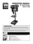
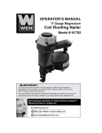
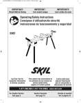
15˝ VARIABLE SPEED
DRILL PRESS
Model # 4225
bit.ly/wenvideo
IMPORTANT:
Your new tool has been engineered and manufactured to WEN’s highest standards for dependability,
ease of operation, and operator safety. When properly cared for, this product will supply you years
of rugged, trouble-free performance. Pay close attention to the rules for safe operation, warnings,
and cautions. If you use your tool properly and for intended purpose, you will enjoy years of safe,
reliable service.
NEED HELP? CONTACT US!
Have product questions? Need technical support?
Please feel free to contact us at:
800-232-1195 (M-F 8AM-5PM CST)
[email protected]
WENPRODUCTS.COM
TABLE OF CONTENTS
2
3
4
5
7
8
16
19
20
21
24
Technical Data
General Safety Rules
Specific Safety Rules For Drill Press
Electrical Information
Know Your Drill Press
Assembly and Adjustments
Operation
Maintenance
Troubleshooting
Exploded View and Parts List
Warranty
TECHNICAL DATA
Model Number:
Motor:
Speed:
Chuck Capacity:
Stroke:
Capacity:
Table tilt:
Laser:
Weight:
2
4225
120 V, 60 Hz, 8.6 A, 2/3 HP
280-3300 RPM (no load)
1/12--5/8˝
4˝
7.5˝ (chuck to column)
48-3/4˝ (chuck to base)
0 to 45° left and right
Class III, transformer powered
154 lb
GENERAL SAFETY RULES
Safety is a combination of common sense, staying alert and knowing how your item works. SAVE THESE
SAFETY INSTRUCTIONS.
WARNING: To avoid mistakes and serious injury, do not plug in your tool until the following
steps have been read and understood.
1. READ and become familiar with this entire instruction manual. LEARN the tool’s applications, limitations,
and possible hazards.
2. AVOID DANGEROUS CONDITIONS. Do not use power tools in wet/damp areas or expose them to
rain. Keep work areas well lit.
3. DO NOT use power tools in the presence of flammable liquids or gases.
4. ALWAYS keep your work area clean, uncluttered, and well lit. DO NOT work on floor surfaces that are
slippery with sawdust or wax.
5. KEEP BYSTANDERS AT A SAFE DISTANCE from the work area, especially when the tool is operating.
NEVER allow children or pets near the tool.
6. DO NOT FORCE THE TOOL to do a job for which it was not designed.
7. DRESS FOR SAFETY. Do not wear loose clothing, gloves, neckties, or jewelry (rings, watches, etc.) when
operating the tool. Inappropriate clothing and items can get caught in moving parts and draw you in. ALWAYS
wear non-slip footwear and tie back long hair.
8. WEAR A FACE MASK OR DUST MASK to fight the dust produced by sawing operations.
WARNING: Dust generated from certain materials can be hazardous to your health. Always
operate the tool in a well-ventilated area and provide for proper dust removal. Use dust collection
systems whenever possible.
9. ALWAYS remove the power cord plug from the electrical outlet when making adjustments, changing parts,
cleaning, or working on the tool.
10. KEEP GUARDS IN PLACE AND IN WORKING ORDER.
11. AVOID ACCIDENTAL START-UPS. Make sure the power switch is in the OFF position before plugging
in the power cord.
12. REMOVE ADJUSTMENT TOOLS. Always make sure all adjustment tools are removed from the saw
before turning it on.
13. NEVER LEAVE A RUNNING TOOL UNATTENDED. Turn the power switch to OFF. Do not leave
the tool until it has come to a complete stop.
3
GENERAL SAFETY RULES
14. NEVER STAND ON A TOOL. Serious injury could result if the tool tips or is accidentally hit. DO NOT store
anything above or near the tool.
15. DO NOT OVERREACH. Keep proper footing and balance at all times. Wear oil-resistant rubber-soled footwear. Keep the floor clear of oil, scrap, and other debris.
16. MAINTAIN TOOLS PROPERLY. ALWAYS keep tools clean and in good working order. Follow instructions for lubricating and changing accessories.
17. CHECK FOR DAMAGED PARTS. Check for alignment of moving parts, jamming, breakage, improper
mounting, or any other conditions that may affect the tool’s operation. Any part that is damaged should be properly
repaired or replaced before use.
18. MAKE THE WORKSHOP CHILDPROOF. Use padlocks and master switches and ALWAYS remove starter keys.
19. DO NOT operate the tool if you are under the influence of drugs, alcohol, or medication that may affect your
ability to properly use the tool.
20. USE SAFETY GOGGLES AT ALL TIMES that comply with ANSI Z87.1. Normal safety glasses only have
impact resistant lenses and are not designed for safety. Wear a face or dust mask when working in a dusty environment. Use ear protection such as plugs or muffs during extended periods of operation.
SPECIFIC RULES FOR DRILL PRESS
WARNING: Do not operate this tool until it is completely assembled and installed according to
the instructions.
1. Never turn the drill press on until the table is clear of all foreign objects (tools, scraps, etc.).
2. Always keep hands and fingers away from the drill bit.
3. Do not drill materials without a flat surface unless a suitable support is used (clamp or vice).
4. Never start the drill press with the drill bit pressed against the workpiece.
5. Make sure the table lock is tightened before starting the drill press.
6. Never layout, assemble, or set-up any work on the table while the drill is on.
7. Make sure the drill bit is securely locked in the chuck.
8. Make sure the chuck key is removed from the chuck before turning power on.
9. Adjust the table or depth stop to avoid drilling into the table.
4
SPECIFIC RULES FOR DRILL PRESS
10. Always stop the drill before removing scrap pieces from the table.
11. Use clamps or a vise to secure a workpiece to the table. This will prevent the workpiece from rotating with the
drill bit.
12. Do not wear gloves when operating a drill press.
13. Set the drill press to the speed that is appropriate for the material being drilled.
14. If any part of the drill press is missing/damaged or if the electrical components fail to perform properly, shut the
power OFF and unplug the drill press. Replace missing, damaged or failed parts before resuming operation.
15. Before leaving the machine, shut the power off, remove the drill bit and clean the table.
ELECTRICAL INFORMATION
GROUNDING INSTRUCTIONS
IN THE EVENT OF A MALFUNCTION OR BREAKDOWN, grounding provides the path of least resistance
for an electric current and reduces the risk of electric shock. This tool is equipped with an electric cord that has an
equipment grounding conductor and a grounding plug. The plug MUST be plugged into a matching outlet that is
properly installed and grounded in accordance with ALL local codes and ordinances.
DO NOT MODIFY THE PLUG PROVIDED. If it will not fit the outlet, have the proper outlet installed by a
licensed electrician.
IMPROPER CONNECTION of the equipment grounding conductor can result in electric shock. The conductor with the green insulation (with or without yellow stripes) is the equipment grounding conductor. If repair or
replacement of the electric cord or plug is necessary, DO NOT connect the equipment grounding conductor to a
live terminal.
CHECK with a licensed electrician or service personnel if you do not completely understand the grounding instructions or whether the tool is properly grounded.
USE ONLY THREE-WIRE EXTENSION CORDS that have three-pronged plugs and outlets that accept the
tool’s plug as shown in Fig. A. Repair or replace a damaged or worn cord immediately.
CAUTION: In all cases, make certain the outlet in question is properly grounded. If you are not sure, have a licensed electrician check the outlet.
FIGURE A
WARNING: This tool is for indoor use only. Do not expose to rain or use in
damp locations.
5
ELECTRICAL INFORMATION
GUIDELINES FOR USING EXTENSION CORDS
Make sure your extension cord is in good condition. When using an extension cord, be sure to use one heavy
enough to carry the current your product will draw. An undersized cord will cause a drop in line voltage resulting
in loss of power and overheating. The table below shows the correct size to be used according to cord length and
nameplate ampere rating. When in doubt, use a heavier cord. The smaller the gauge number, the heavier the cord.
AMPERAGE
8.6 A
REQUIRED GAUGE FOR EXTENSION CORDS
25 ft.
50 ft.
100 ft.
150 ft.
18 gauge
16 gauge
14 gauge
12 gauge
Make sure your extension cord is properly wired and in good condition. Always replace a damaged extension cord
or have it repaired by a qualified person before using it.
Protect your extension cords from sharp objects, excessive heat and damp/wet areas.
Use a separate electrical circuit for your tools. This circuit must not be less than a #12 wire and should
be protected with a 15 A time-delayed fuse. Before connecting the motor to the power line, make sure
the switch is in the OFF position and the electric current is rated the same as the current stamped on
the motor nameplate. Running at a lower voltage will damage the motor.
WARNING: This tool must be grounded while in use to protect the operator from electric shock.
6
KNOW YOUR DRILL PRESS
Fig. 1
A
B
C
D
E
F
G
H
Digital Speed Readout
ON/OFF Switch
Depth Scale
Chuck
Table
Laser Switch
Feed Handles
Pulley Cover Knob
I
J
K
L
M
N
O
P
Pulley Cover
Column
Rack
Crank Handle
Column Base
Base
Table Lock Handle
Bevel Lock Bolt
Q
R
S
T
U
V
W
X
Location Pin
Bevel Scale
Table Support Lock Handle
Speed Control Handle
LED Worklight Switch
Power Cord
Tension Knob
Lock Handle
7
ASSEMBLY AND ADJUSTMENTS
UNPACKING (Fig. 2)
Unpack the drill press and all of its parts. Compare against the list below. Do not discard the carton or any packaging until the drill press is completely assembled.
To protect the drill press from moisture, a protective coating has been applied to the machine’s surfaces. Remove
this coating with a soft cloth moistened with kerosene or WD-40®. Do not use acetone, gasoline, or lacquer thinner to clean. Apply a coat of good paste wax to the table and column. Wipe all parts with a clean dry cloth.
Fig. 2
A
B
C
D
E
F
G
8
Head/Motor Assembly
Column Assembly
Table
Base
Hex Keys - 3, 4, 5
Table Support Lock Handle
Table Lock Handle
H
I
J
K
L
M
N
O
Bolt M12 X 35
Chuck
Chuck Arbor
Chuck Key
Feed Handle
Speed Handle
Wedge
Crank Handle
ASSEMBLY AND ADJUSTMENTS
WARNING: If any part is missing or damaged, do not plug the drill press in until the missing or damaged
part is repaired or replaced.
The column assembly (column, column support, rack, rack collar,
and table support bracket) must be attached to the base. The table
and table support handles must be attached to the table support
bracket. The motor housing must be attached to the column.
Tools needed for assembly
• Adjustable wrench
• screwdriver
• Hammer and block of wood
COLUMN ASSEMBLY TO BASE (Fig. 3)
1. Place the column tube (1) on the base (2), aligning the column
support holes to the base holes.
Fig. 3
2. Install a hex head bolt (3) in each column support hole and
tighten bolts using the adjustable wrench.
TABLE TO TABLE SUPPORT BRACKET (Fig. 4)
1. Place the crank handle (1) onto the shaft (2) of the table bracket
so the flat of the shaft is under the set screw (3). Tighten the set
screw.
2. Thread the table lock handle (4) into the front of the table support bracket.
3. Thread the table support lock handle into the rear of the table
support bracket (not shown).
4. Position the table (5) in the same direction as the base. Install
the table and tighten the table lock handle (4) and support lock
handle.
Fig. 4
9
ASSEMBLY AND ADJUSTMENTS
DRILL PRESS HEAD TO COLUMN (Fig. 5)
CAUTION: The drill press head is heavy. To avoid injury, two
people should lift it into position.
1. Carefully lift the drill press head assembly (1) and position it
over the column (2).
2. Place the mounting opening (3) on the drill press head over the
top of the column. Make sure the drill press head is seated properly on the column.
Fig. 5
3. Align the direction of the drill press head with the direction of
the base and the table.
4. Tighten the set screw (4) using a hex key.
FEED HANDLES (Fig. 6)
1. Insert the three speed handles (1) into the threaded openings on
the feed hub (2).
2. Manually tighten handles into openings.
Note: When using the drill press, one or two of the feed handles
may be removed if an unusually-shaped workpiece interferes with
handle rotation.
2
SPEED HANDLE (Fig. 7)
1. Insert the feed handle (1) into the threaded opening on the
speed hub (2).
2. Manually tighten handle into opening.
1
10
Fig. 7
ASSEMBLY AND ADJUSTMENTS
MOUNT THE DRILL PRESS (Fig. 8)
The drill press must be securely fastened through the mounting
holes to a stand or workbench with heavy-duty fasteners. This will
prevent the drill press from tipping over, sliding, or walking during
operation.
IMPORTANT: If the stand or workbench has a tendency to move
during operation, fasten the workbench securely to the floor.
LED BULB
A LED bulb has been assembled in the socket of the head.
Fig. 8
Warning: To reduce risk of fire, DO NOT use a light bulb greater
than 40 watts. When changing the light bulb, always check that the
power switch is in the OFF position and the plug is disconnected
from its power source.
INSTALL THE CHUCK (Fig. 9)
1. Inspect and clean the taper hole in the chuck and the spindle. Remove all grease, coatings, and particles from the chuck and spindle
surfaces with a clean cloth.
2. Open the chuck jaws by manually turning the chuck barrel clockwise. Make sure the jaws are completely recessed inside the chuck.
3. Insert the chuck arbor into the opening at the top of the chuck.
4. Seat the chuck and chuck arbor on the spindle by placing a block
of wood (not included) under the chuck and tapping the wood with
a hammer (not included). Alternatively, tap the chuck with a rubber
mallet (not included).
Fig. 9
CAUTION: To avoid damaging the chuck, make sure the jaws are
completely recessed into the chuck. Do not use a metal hammer to
drive the chuck into the spindle.
REMOVE THE CHUCK (Fig. 10)
1. Turn the feed handles (1) to lower the chuck to the lowest position.
Wedge
2. Slide the wedge into the opening in the quill. Tap on the wedge
using a hammer (not included). The chuck and arbor will drop out.
Note: To avoid possible damage to the drill or chuck, be prepared
to catch the chuck as it falls.
Fig. 10
11
ASSEMBLY AND ADJUSTMENTS
RAISE OR LOWER THE TABLE (Fig. 11)
1. Loosen the support lock handle (1) and turn the crank handle (2)
until the table is at the desired height.
1
2. Tighten the support lock handle before drilling.
ROTATE THE TABLE (Fig. 11)
1. Loosen the support lock handle (1) and turn the table around the
column to the desired position.
2
Fig. 11
Note: The rack should rotate around the column with the table support bracket. If the rack binds and does not rotate, slightly loosen
the set screw in the rack collar.
2. Tighten the support lock before drilling.
TILT THE TABLE (Fig. 12)
1. Rotate the table clockwise with the fork wrench. Pull out the location pin. Put the location pin and nut in suitable area.
2. Rotate the bolt (1) counterclockwise with a wrench to loosen it.
3. Adjuste the angle of the table.
4. Tighten the bolt with fork wrench.
ADJUST THE TABLE TO BE HORIZONTAL
1. Rotate the bolt (1) counterclockwise with a wrench to loosen it.
2. Rotate the table to 0˚.
3. Hit the location pin (2) into the location hole in the table support
with a hammer.
4. Tighten the nut of the location pin (2) slightly.
5. Lock the bolt (1) with wrench.
12
Fig. 12
ASSEMBLY AND ADJUSTMENTS
WARNING: To avoid injury, make sure the chuck key is removed
from the chuck before starting any drilling operation.
INSTALLING A DRILL BIT (Fig. 13)
1. Place the chuck key (1) into the side keyhole of the chuck (2),
meshing the key with the gear teeth.
2. Turn the chuck key counterclockwise to open the chuck jaws (3).
3. Insert a drill bit (4) into the chuck far enough to obtain the maximum grip of the chuck jaws.
Fig. 13
4. Center the drill bit in the chuck jaws before the final tightening of
the chuck.
5. Tighten the chuck jaws using the chuck key to ensure that the drill
bit will not slip while drilling.
6. Remove the chuck key.
SQUARING THE TABLE TO THE DRILL BIT (Fig. 14)
1. Insert a 3” long drill bit (1) into the chuck (2) and tighten the jaws
with the chuck key.
Fig. 14
2. Raise the table with the crank handle (3). Lock the table (4) approximately 1” below the drill bit.
3. Place a combination square (5; not included) on the table as shown, placing the long straight edge of the combination square against the drill bit. Make sure the drill bit is parallel/aligned exactly to the straight edge of the
square.
4. If an adjustment is needed, loosen the bevel lock bolt (6) with a wrench.
5. Tilt the table slightly, until the combination straight edge is aligned perfectly with the drill bit.
6. Tighten the bevel lock when square.
Note: Adjustments for the correct function of your drill press return spring have been done by the factory. Please
do not modify them. However, prolonged use of the drill press may make some readjustments necessary.
13
ASSEMBLY AND ADJUSTMENTS
ADJUSTING THE LASER (Fig. 15 and 16)
WARNING: Do not stare directly at the laser beam. Please observe all
safety rules.
• Never aim the beam at a person or an object other than the workpiece.
• Do not project the laser beam into the eyes of others.
• Always make sure the laser beam is aimed at a workpiece that does
not possess reflective surfaces, as the laser beam could project into your
eyes or the eyes of others.
Fig. 15
1. Place a workpiece on the table.
2. Turn the laser switch (1) to the ON position.
2
3. Lower the drill bit to meet the workpiece (2). The two laser lines should
cross where the drill meets the workpiece.
4. If the laser needs to be adjusted:
Fig. 16
a. Using a 3 mm hex key, turn the laser adjustment set screws (3) counterclockwise.
b. Rotate the laser light housing (4) until the two laser lines intersect where the drill meets the workpiece.
DO NOT stare directly at the laser lines.
5. Re-tighten the adjustment set screws (3).
SPINDLE RETURN SPRING (Fig. 17)
The spindle is equipped with an auto-return mechanism. The main components are a spring and a notched housing. The spring was properly adjusted at the factory and should not be readjusted unless absolutely necessary.
1. Unplug the drill press.
4
1
2. Place a screwdriver into the loop (1) to hold the spring in place.
2
5
3. Loosen the two housing nuts (2) approximately 1/4” (6 mm). Do not remove
the nuts from the threaded shaft. Do not allow the spring or spring housing to
slip out of control.
4. While firmly holding the spring housing (3), carefully pull the spring housing
out until it clears the raised notch (4).
Fig. 17
3
5. Turn the housing so that the next notch (5) is engaged with the raised notch (4).
• To increase the spindle return tension, turn the spring housing counter-clockwise.
• To decrease the tension, turn the spring housing clockwise.
6. Tighten the two housing nuts. Do not overtighten the two nuts. If the nuts are tightened too much, the movement of the spindle and feed handles will become sluggish.
14
ASSEMBLY AND ADJUSTMENTS
ANGULAR “PLAY” OF THE SPINDLE (Fig. 18)
Move the spindle to the lowest downward position and hold in place.
Try to make the spindle revolve around its axis while also moving it
with a side motion. If there is too much “play”, proceed as follows:
1. Loosen the lock nut (1).
2. Without obstructing the upward and downward motion of the
spindle, turn the screw (2) clockwise to eliminate the “play.” Note: A
little bit of “play” is normal.
Fig. 18
3. Tighten the lock nut (1).
REPLACING THE BELT (Fig. 19)
1
WARNING: Disconnect the drill press from the power source before replacing the belt.
Belt tension and drill press speed is controlled by automatic adjustments made to the diameter of the front spindle when the drive
handle is moved.
Note: See page 19 for information on the variable speed function of
this drill press.
2
4
3
Fig. 19
1. Remove the screw that secures the housing cover (1). Open the housing cover.
2. Remove the belt (2) from the housing cover if it is broken. If it is not broken, but is too stretched to operate
correctly, work the belt off the drive (motor) spindle (3). Then remove the belt from the front spindle (4).
3. Replace the belt by putting a new belt over the front spindle (4) and carefully sliding the belt over the drive (motor) spindle (3).
WARNING: Do not change the drive speed when the drill press is turned off.
15
OPERATION
DRILL PRESS ON/OFF SWITCH (Fig. 20)
1. To turn the drill press ON, insert the yellow safety key (1) into the switch
housing (2). As a safety feature, the switch cannot be turned ON without the
safety key.
3
2
2. Flip the switch upward to the ON position.
3. To turn the drill press OFF, flip the switch downward.
4. To lock the switch in the OFF position, remove the safety key (1) from the
switch. Store the safety key in a safe place.
4
Fig. 20
1
LIGHT AND LASER LINE ON/OFF SWITCHES (Fig. 20)
The light switch (3) is located on the lamp cover.
The laser switch (4) is located below the ON/OFF switch on the right.
POSITION THE TABLE AND WORKPIECE (Fig. 21)
Always place a piece of backup material (1) (wood, plywood, etc.) on the table
underneath the workpiece (2). This will prevent splintering on the underside
of the workpiece as the drill bit breaks through. To keep the material from
spinning out of control, it must contact the left side (3) of the column as illustrated, or be clamped (4; not included) to the table.
Fig. 21
Note: For small workpieces that cannot be clamped to the table, use a drill
press vise (not included). The vise must be clamped or bolted to the table to avoid injury.
GENERAL DRILLING GUIDELINES - DRILLING A HOLE
WARNING: To prevent the workpiece and the backup material from slipping from your hand
while drilling, position the workpiece and backup material to the left side of the column. If the workpiece and the
backup material are not long enough to reach the column, clamp the workpiece and backup material to the table.
Failure to do this could result in personal injury.
1. Mark where you want to drill in workpiece by using a center punch or a sharp nail or turn ON the laser to mark
your drilling point.
2. Before turning the drill press ON, turn the feed handles to bring the drill bit down. Line the drill bit tip up with
the mark. Clamp the workpiece in place.
3. Turn ON the drill press and pull down on the feed handles with the appropriate force needed to allow the drill
bit to drill the material.
Note: Feeding too slowly might cause the drill bit to turn in the chuck. Feeding too rapidly
might stop the motor, cause the belt to slip, force the workpiece loose, or break the drill bit. Practice with scrap
material to get the feel of the machine before attempting to do any drilling operation.
16
OPERATION
ADJUST THE DRILLING DEPTH (Fig. 22)
The depth gauge controls the maximum distance the drill bit will move up or
down.
2
3
1
4
To stop the drill bit at a pre-measured depth, loosen the depth scale knob (1) by
push button (2) until the bottom of the knob is aligned with the desired depth
mark (3) on the gauge scale.
Drilling an unmeasured blind hole (not all the way through the workpiece) to a
given depth can be done using either the depth scale method or the workpiece
method.
Fig. 22
DEPTH SCALE METHOD (Fig. 22)
1. Make sure the 0 (“ or mm) mark on the depth gauge rests at the top edge of the
metal support (4) when the quill is fully retracted.
2. Put the workpiece on the table and raise the table until the tip of the drill bit just
touches the top of the workpiece. Lock the table in place.
6
5
3. Determine the drill depth for this workpiece.
4. Rotate the depth knob (2) until it is aligned with the desired depth mark (3) (for
example, 1”) on the gauge scale.
Fig. 23
5. The chuck will be stopped at the distance selected on the depth scale.
WORKPIECE METHOD (Fig. 22 and 23)
1. Mark the desired depth (5) of the drill hole on the side of the workpiece.
2. With the drill press in the OFF position, bring the drill bit (6) down until the tip is even with the mark.
3. Holding the feed handles at this position, rotate the depth knob (2) until it meets the metal support.
4. The chuck and the drill bit will now be stopped at the distance selected on the depth scale.
17
OPERATION
DRILLING SPEEDS
There are a few important factors to keep in mind when determining the best drilling speed:
• Material type
• Hole size
• Drill bit or cutter type
• Quality desired
Smaller drill bits require greater speed than larger drill bits. Softer materials require greater speed than harder
materials. See page 19 for recommended speeds for particular materials.
DRILLING METAL
• Use metal-piercing twist drill bits.
• It is always necessary to lubricate the tip of the drill with oil to prevent overheating of the drill bit.
• All metal workpieces should be clamped down securely. Any tilting, twisting, or shifting causes a rough drill
hole, and increases the potential of drill bit breakage.
• Never hold a metal workpiece with your bare hands. The cutting edge of the drill bit may seize the workpiece and throw it, causing serious injury. The drill bit will break if the metal piece suddenly hits the column.
• If the metal is flat, clamp a piece of wood under it to prevent turning. If it cannot be laid flat on the table,
then it should be blocked and clamped.
DRILLING WOOD
• Brad point bits are preferred. Metal piercing twist bits may be used on wood.
• Do not use auger bits. Auger bits turn so rapidly that they can lift the workpiece off of the table and whirl it
around.
• Always protect the drill bit by positioning the table so that the drill bit will enter the center hole when drilling
through the workpiece.
• To prevent splintering, feed the drill bit slowly right as the bit is about to cut through to the backside of the
workpiece.
• To reduce splintering and protect the point of the bit, use scrap wood as a backing or a base block under the
workpiece.
FEEDING THE DRILL BIT
• Pull down on the feed handles with only enough force to allow the drill bit to cut.
• Feeding too rapidly might stall the motor, cause the belt to slip, damage the workpiece, or break the drill bit.
• Feeding too slowly will cause the drill bit to heat up and burn the workpiece.
MECHANICAL VARIABLE SPEED (Fig. 24)
This is a mechanical variable speed drill press. To increase or decrease the
speed when operating, raise or lower the speed handle (1).
Use the following table to determine the recommended speed for the drill size
you are using and the type of material you are to drill. While drilling, check
the speed on the digital speed readout (2) located at the front of the drill press.
Warning: Do not change speed using variable speed handle without turning on
the machine.
18
2
1
Fig. 24
OPERATION
ADJUSTING THE MECHANICAL VARIABLE SPEED RANGE
To adjust the variable speed range from 280-1000 RPM to 1000-3300 RPM, first open the belt cover of the drill
press. Loosen the spindles using the Lock Handle located on the right side of the drill press. Slide the belt into
either Belt A-1 position or Belt B-2 position (seen below in the “Recommended Working Speeds” chart) depending on the RPM range needed. Retighten the spindles using the Lock Handle and then shut the belt cover.
WARNING: Do not manually adjust belt position on the spindles when machine is on.
Recommended speed for drill bit size and materials
MAINTENANCE
WARNING: For your safety, turn the switch off and remove the plug from the power supply before maintaining
or lubricating the drill press.
Vacuum sawdust or metal shavings that accumulate in and on the motor, pulley housing, table, and work surface.
Apply a light coat of paste wax to the column and table to help keep these surfaces clean and rust-free.
The ball bearings in the spindle and the V-belt pulley assembly are greased and permanently sealed. Pull the
spindle down and oil the spindle sleeve moderately every three months.
Lubricate the table bracket and locking knobs if they become difficult to use.
CAUTION: All servicing of the drill press should be performed by a qualified service technician.
19
TROUBLESHOOTING
PROBLEM
Noisy operation
SOLUTIONS
1) Adjust the belt tension (See REPLACE THE
BELT section)
2) Lubricate the spindle
3) Tighten the retaining nut on the pulley insert
4) Tighten the set screw on the side of the motor pulley
The drill bit burns or 1) Drilling at the incorrect speed
1) Change the speed
smokes
2) The wood chips are not coming out 2) Retract the drill bit frequently to clear the
of the hole
chips
3) Dull drill bit
3) Resharpen or replace the drill bit
4) Feeding the workpiece too slowly
4) Feed fast enough to cut the workpiece
5) Not lubricated
5) Lubricate the drill bit with cutting oil or motor oil
Excessive drill run
1) Bent drill bit
1) Replace the drill bit
out or wobble,
2) Bit improperly installed in the
2) Reinstall the bit.
drilled hole is not
chuck
3) Replace the bearing. Take to a qualified
round
3) Worn spindle bearings
service technician
4) Lengths of cutting flutes or angles
4) Resharpen the drill bit correctly or replace
not appropriate for the hardness of the with the appropriate type.
wood grain
5) Reinstall the chuck.
5) Chuck not properly installed
Drill bit binds in the 1) The workpiece is pinching the bit
1) Support or clamp the workpiece.
workpiece
2) Excessive feed pressure
2) Feed more slowly.
Spindle returns too
Coil spring has improper tension
Adjust the coil spring tension
slowly or too quickly
Chuck falls off
Dirt, grease, or oil on the tapered sur- Clean the tapered surface of both the chuck and
spindle
face on the spindle or in the chuck
spindle with a household detergent.
Motor will not run
1) Defective or broken switch
1) Take to a qualified service technician
2) Defective or damaged power cord
2) Take to a qualified service technician
3) Open circuit, loose connections, or 3) Take to a qualified service technician
burned out motor
4) Check the power line for the proper voltage.
4) Low voltage
Use another circuit or have a qualified electrician upgrade the service.
Motor stalls
1) Short circuit in motor
1) Take to a qualified service technician
2) Incorrect fuses or circuit breakers
2) Replace with correct fuse or circuit breaker
3) Overloaded circuit
for the circuit
4) Low Voltage
3) Turn off other machines and retry
4) Check the power line for the proper voltage.
Use another circuit or have a qualified electrician upgrade the service.
20
CAUSES
1) Incorrect belt tension
2) Dry spindle
3) Loosed spindle pulley
4) Loosed motor pulley
EXPLODED VIEW & PARTS LIST
21
EXPLODED VIEW & PARTS LIST
Item#
1
2
3
4
5
6
7
8
9
10
11
12
13
14
15
16
17
18
19
20
21
22
23
24
25
26
27
28
29
30
31
32
33
34
35
36
37
38
39
40
41
42
43
44
22
Part#
4225-001
4225-002
4225-003
4225-004
4225-005
4225-006
4225-007
4225-008
4225-009
4225-010
4225-011
4225-012
4225-013
4225-014
4225-015
4225-016
4225-017
4225-018
4225-019
4225-020
4225-021
4225-022
4225-023
4225-024
4225-025
4225-026
4225-027
4225-028
4225-029
4225-030
4225-031
4225-032
4225-033
4225-034
4225-035
4225-036
4225-037
4225-038
4225-039
4225-040
4225-041
4225-042
4225-043
4225-044
Description
V belt W20*7*617
Screw M8x10
Motor pulley wheel a
Motor pulley wheel b
Pulley spring
Set screw M8x25
Motor wheel
Lock nut M10
Flat washer 10
Ball bearing 6201RZ
Key A-4x66
Quill a
Key A-4x12
Ball bearing
Axle
Worm M6x16
Circlip
Circlip
Cam
Ball bearing 61907RZ
Circlip
Spindle pulley a
spindle pulley b
Board
Wire clip
Screw M4x7
Column Tube
Screw M8x12
Spring
Washer 8
Screws M8x16
Driving Sleeve
Key
Circlip
Ball bearing
Circlip
V belt M29
Screw M8x8 ?
Motor pulley
Key C-5x35
Screw M8x16
Motor
Washer 8
Nut M8
Qty
1
1
1
1
1
1
1
2
2
1
1
1
1
1
1
3
1
1
1
1
1
1
1
1
1
1
1
1
1
1
2
1
1
2
3
1
1
2
1
1
4
1
4
4
Item#
45
46
47
48
49
50
51
52
53
54
55
56
57
58
59
60
61
62
63
64
65
66
67
68
69
70
71
72
73
74
75
76
77
78
79
80
81
82
83
84
85
86
87
88
Part#
4225-045
4225-046
4225-047
4225-048
4225-049
4225-050
4225-051
4225-052
4225-053
4225-054
4225-055
4225-056
4225-057
4225-058
4225-059
4225-060
4225-061
4225-062
4225-063
4225-064
4225-065
4225-066
4225-067
4225-068
4225-069
4225-070
4225-071
4225-072
4225-073
4225-074
4225-075
4225-076
4225-077
4225-078
4225-079
4225-080
4225-081
4225-082
4225-083
4225-084
4225-085
4225-086
4225-087
4225-088
Description
Screw M6x12
Pulley cover
Motor mount
Nut M12
Washer 12
Motor rod 2
Motor rod 1
Washer sponge
Plastic knob M10x30
Cylindrical spring pin 6*30
Screw M6*12
Wire fixed block
Head
Rubber bush
Screw M10x12
Screw M5x12
Wire fixed plate
LED BULB 120V 1.3W
Block
Circlip
Motor extension lever
Handle knob
Feed handle
Hub
Spring pin 5x30
Pinion shaft
Depth location bush
Screw ST2.9x6.5
Receiver Seat
Readout base
Chuck key holder
Washer 5
Washer 5
Switch box
Screw M5x25
Screw M5x16
Readout transformer
Switch box cover
On/Off switch
Screw ST4.2x16
Laser switch
Gear shaft
Base
Speed handle spring
Qty
5
1
1
2
2
1
1
4
2
2
7
1
1
2
2
7
3
1
1
1
1
3
3
1
1
1
1
2
1
1
1
2
2
1
1
2
1
1
1
4
1
1
1
1
EXPLODED VIEW & PARTS LIST
Item#
89
90
91
92
93
94
95
96
97
98
99
100
101
102
103
104
105
106
107
108
109
110
111
112
113
114
115
116
117
118
119
120
121
122
Part#
4225-089
4225-090
4225-091
4225-092
4225-093
4225-094
4225-095
4225-096
4225-097
4225-098
4225-099
4225-100
4225-101
4225-102
4225-103
4225-104
4225-105
4225-106
4225-107
4225-108
4225-109
4225-110
4225-111
4225-112
4225-113
4225-114
4225-115
4225-116
4225-117
4225-118
4225-119
4225-120
4225-121
4225-122
Description
Speed handle base
Nut M10
Speed handle
Handle knob
Screw M5x15
Laser cover
Screw M6x25
Nut M6
Laser base
Set screw M6x10
Laser
Spring baffle
Coil spring
Spring base
Nut
Scale
Mounting base
Screw M6x25
Screw M8x35
Adjusting Nut
Scale base
Set screw M10x30
Slide bush
Spring
Location block
Round nut
Washer 18
Ball bearing 6203Z
Rubber pad
Quill b
Spindle
Chuck abor
Chuck
Chuck key
Qty
1
1
1
1
3
2
2
4
2
4
2
1
1
1
2
1
1
2
1
1
1
1
1
1
1
1
1
1
1
1
1
1
1
1
Item#
123
124
125
126
127
128
129
130
131
132
133
134
135
136
137
138
139
140
141
142
143
144
145
146
147
148
149
150
151
152
153
154
155
156
Part#
4225-123
4225-124
4225-125
4225-126
4225-127
4225-128
4225-129
4225-130
4225-131
4225-132
4225-133
4225-134
4225-135
4225-136
4225-137
4225-138
4225-139
4225-140
4225-141
4225-142
4225-143
4225-144
4225-145
4225-146
4225-147
4225-148
4225-149
4225-150
4225-151
4225-152
4225-153
4225-154
4225-155
4225-156
Description
Qty
Rack collar
Column
Rack
Handle
Crank
Worm
Inner shaft
Inner gear
Work table support
Locking knob
Bolt M16x40
Nut
Location pin
Work table support
Bevel scale
Label rivet
Indicator
Screw M5x6
Support locking knob
Column base
Bolt M12x35
Base
Work table
Depth scale
Nut M10
Key A-3x25
LED worklight
worklight support
worklight support cover
Wedge block
Hex key 3
Hex key 5
Power cord
Hex key 4
1
1
1
1
1
1
1
1
1
1
1
1
1
1
1
2
1
2
1
1
4
1
1
1
1
1
1
1
1
1
1
1
1
1
23
LIMITED TWO YEAR WARRANTY
WEN Products is committed to building tools that are dependable for years. Our warranties are consistent with
this commitment and our dedication to quality.
LIMITED WARRANTY OF WEN CONSUMER POWER TOOLS PRODUCTS FOR HOME USE
GREAT LAKES TECHNOLOGIES, LLC (“Seller”) warrants to the original purchaser only, that all WEN consumer power tools will be free from defects in material or workmanship for a period of two (2) years from date of
purchase. Ninety days for all WEN products, if the tool is used for professional use.
SELLER’S SOLE OBLIGATION AND YOUR EXCLUSIVE REMEDY under this Limited Warranty and,
to the extent permitted by law, any warranty or condition implied by law, shall be the repair or replacement of
parts, without charge, which are defective in material or workmanship and which have not been misused, carelessly handled, or misrepaired by persons other than Seller or Authorized Service Center. To make a claim under
this Limited Warranty, you must return the complete power tool product; transportation prepaid, to Great Lakes
Technologies, LLC – 1675 Holmes Road – Elgin, IL. 60123 with a copy of the original receipt which is legible
and clearly defines Date of Purchase including month and year and Place of Purchase.
THIS LIMITED WARRANTY DOES NOT APPLY TO ACCESSORY ITEMS SUCH AS CIRCULAR
SAW BLADES, DRILL BITS, ROUTER BITS, JIGSAW BLADES, SANDING BELTS, GRINDING
WHEELS AND OTHER RELATED ITEMS.
ANY IMPLIED WARRANTIES SHALL BE LIMITED IN DURATION TO TWO (2) YEARS FROM
DATE OF PURCHASE. SOME STATES IN THE U.S., SOME CANADIAN PROVINCES DO NOT ALLOW LIMITATIONS ON HOW LONG AN IMPLIED WARRANTY LASTS, SO THE ABOVE LIMITATION MAY NOT APPLY TO YOU.
IN NO EVENT SHALL SELLER BE LIABLE FOR ANY INCIDENTAL OR CONSEQUENTIAL DAMAGES (INCLUDING BUT NOT LIMITED TO LIABILITY FOR LOSS OF PROFITS) ARISING FROM
THE SALE OR USE OF THIS PRODUCT. SOME STATES IN THE U.S. AND SOME CANADIAN
PROVINCES DO NOT ALLOW THE EXCLUSION OR LIMITATION OF INCIDENTAL OR CONSEQUENTIAL DAMAGES, SO THE ABOVE LIMITATION OR EXCLUSION MAY NOT APPLY TO
YOU.
THIS LIMITED WARRANTY GIVES YOU SPECIFIC LEGAL RIGHTS, AND YOU MAY ALSO HAVE
OTHER RIGHTS WHICH VARY FROM STATE TO STATE IN THE U.S., PROVINCE TO PROVINCE
IN CANADA AND FROM COUNTRY TO COUNTRY.
THIS LIMITED WARRANTY APPLIES ONLY TO PORTABLE ELECTRIC TOOLS, BENCH POWER TOOLS, OUTDOOR POWER EQUIPMENT AND PNEUMATIC TOOLS SOLD WITHIN THE
UNITED STATES OF AMERICA, CANADA AND THE COMMONWEALTH OF PUERTO RICO. FOR
WARRANTY COVERAGE WITHIN OTHER COUNTRIES, CONTACT THE WEN CUSTOMER SUPPORT LINE.
24