1
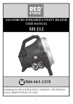
INSTRUCTION MANUAL ENCLOSED
MANUEL D’INSTRUCTION À L’INTÉRIEUR
MANUAL DE INSTRUCCIONES ADJUNTO
STOP
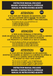
ATTENTION
STOP
IF YOU HAVE ANY PROBLEMS OR QUESTIONS, EMAIL
OR CALL CUSTOMER SERVICE BEFORE YOU RETURN
THIS PRODUCT TO THE STORE WHERE IT WAS PURCHASED.
For Customer Service:
www.tsicustomerservice.com
in English Call: 800-318-9373
ARRÊT
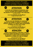
ATTENTION
ARRÊT
SI VOUS AVEZ DES PROBLÈMES OU QUESTIONS,
ENVOYEZ UN COURRIEL AU SERVICE À LA CLIENTÈLE OU
APPELEZ LE SERVICE À LA CLIENTÈLE AVANT DE RETOURNER
CE PRODUIT OÙ VOUS L’AVEZ ACHETÉ.
Pour le service à la clientèle:
www.tsicustomerservice.com
pour le service en français: 800-318-9374
PARE
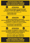
ATENCIÓN
PARE
SI TIENE ALGÚN PROBLEMA O PREGUNTAS, ENVÍE UN
MENSAJE DE CORREO ELECTRÓNICO O LLAME AL SERVICIO
DE ATENCIÓN AL CLIENTE ANTES DE DEVOLVER ESTE
PRODUCTO A LA TIENDA EN LA QUE LO COMPRÓ.
Servicio de atención al cliente:
www.tsicustomerservice.com
Línea para llamadas en español: 800-318-9374
INSTRUCTION MANUAL ENCLOSED
MANUEL D’INSTRUCTION À L’INTÉRIEUR
MANUAL DE INSTRUCCIONES ADJUNTO
240V Utility Heater
Operating Manual
Model #: DFH-107-T
CONSUMER SAFETY INFORMATION
PLEASE READ THIS MANUAL BEFORE INSTALLING
AND OPERATING THIS APPLIANCE.
WARNING
IF THE INFORMATION IN THIS MANUAL IS NOT FOLLOWED EXACTLY, AN
ELECTRIC SHOCK OR FIRE MAY RESULT CAUSING PROPERTY DAMAGE,
PERSONAL INJURY OR LOSS OF LIFE.
DO NOT STORE OR USE GASOLINE OR OTHER FLAMMABLE VAPORS AND
LIQUIDS IN THE VICINITY OF THIS OR ANY OTHER APPLIANCE.
Thank you and congratulations on your purchase of a Twin-Star International, Inc.
Electric Space Heater. Please read the Installation & Operating Instructions before
using this appliance.
IMPORTANT: Read all instructions and warnings carefully before starting installation.
Failure to follow these instructions may result in a possible electric shock, firehazard
and/or injury and will void the warranty.
You will need the following tools to install your electric heater:
Screwdriver, needle nose pliers, pliers, electric Drill and 1/4 in bit, adjustable wrench.
Hardware Needed: You will also need the following hardware for installation:
Enough properly sized insulated copper conductor (with ground) wire to run power
from the breaker/fuse to the heater, only use copper wire rated at least 75°C. Do not
use aluminum wire with this unit. Refer to local and national electrical codes for proper
supply wire selection.
For Customer Service:
In English Call: 800-318-9373
In Spanish Call: 800-318-9374
In French Call: 800-318-9374
Twin-Star International, Inc.
Delray Beach, FL 33445
Made in China • Printed in China
E-1
Made in China
Printed in China
©2013,Twin-Star International,Inc.
Rev-A
IMPORTANT INSTRUCTIONS
When using electrical appliances, basic precautions should always be followed to reduce the risk of fire, electrical shock, and injury to persons including the following:
1. Read all instructions before using this heater.
2. WARNING – Risk of fire. Do not use as a residential or household heater.
3. For supply connections use No.12 AWG or larger wires suitable for at least 75°C (167°F).
4. Use copper wires only.
5. CAUTION – High temperature, risk of fire, keep combustible materials, such as furniture, pillows, bedding, papers, clothes and curtains at least 3 feet (0.9 m) from the front of this heater and keep away from the sides and the rear.
6. This heater is hot when in use. To avoid burns, do not let bare skin touch hot surfaces. Don’t move this heater when it is still hot.
7. WARNING - DO NOT INSTALL LESS THAN 8’(2.4M) FROM THE FLOOR AND CLOSER THAN 13”(330MM) TO ANY VERTICAL SURFACE OR WALLS
8. WARNING: In order to avoid overheating, do not cover the heater. It can not be used in a wardrobe.
9. The appliance is not to be used by children or persons with reduced physical, 1 sensory or mental capabilities, or lack of experience and knowledge, unless they have been given supervision or instruction.
10. Children should be supervised not to play with the appliance.
11. Do not operate any heater with a damaged cord or plug or after the heater malfunctions, has been dropped or damaged in any manner. Return heater
to authorized service facility for examination, electrical or mechanical adjustment, or repair.
12. Do not use outdoors.
13. Under no circumstance should this heater be modified. Parts having to be removed for servicing must be replaced prior to operating this heater again.
14. This heater is not intended for use in bathrooms, laundry areas and similar indoor locations. Never locate heater where it may fall into a bathtub or other water container.
15. To disconnect heater, turn the thermostat to minimum and wait until the fan automatically shut off, then cut off the power supply.
16. Connect to properly grounded outlets only.
17. Do not insert or allow foreign objects to enter any ventilation or exhaust opening as this may cause an electric shock or fire, or damage the heater.
18. To prevent a possible fire, do not block air intakes or exhaust in any manner.
19. A heater has hot and arcing or sparking parts inside. Do not use it in areas where gasoline, paint, or flammable liquids are used or stored.
20. Use this heater only as described in this manual. Any other use not recommended by the manufacturer may cause fire, electric shock, or
injury to persons.
SAVE THESE INSTRUCTIONS
E-2
Model # DFH-107-T
!
WARNING
Read Carefully- These instructions are written to help you prevent difficulties
that might arise during installation of heaters. Studying the instructions first may
save you considerable time and money later. Observe the following procedures,
and cut your installation time to a minimum. TO REDUCE RISK OF FIRE OR
ELECTRIC SHOCK;
1. Use minimum 75°C copper wire No.12 AWG only.
2. Heater air flow must be directed parallel to, or away from, adjacent walls.
3. Observe wall, floor, and ceiling clearance requirements.
4. All wiring must conform to national and local electrical codes and the heater
must be grounded as a precaution against possible electrical shock. Heater
circuit must be protected with proper fuse. See Table 1 on page 9.
5. The mounting structure and the anchoring hardware must be capable of
reliable supporting the weight of the heater and, if used, the mounting bracket.
6. All electrical power must be disconnected at the main service box before
installing, inspecting, cleaning or servicing the heater. This is a precaution to
prevent serious electrical shock.
7. Use for Double phase electric power only.
E-3
PARTS LIST
PART
1
2
3
4
5
6
7
8
9
10
11
12
13
14
15
16
17
18
19
20
21
22
23
DESCRIPTION
Louver
Spring
Front mesh frame
Heater bracket
Heating element
Fixing Plates
Fixing Plates
High Temp.Limit Control
Spring clip
Thermal for fan control
Housing
Screw
fan blade
motor
motor bracket
rear mesh frame
Handle
Top cover
Thermostat
Thermostat knob
Power terminal block
Wattage change terminal block
Screw
E-4
!
WARNING
THIS UNIT OPERATES ON 240 VOLTS AC. IMPROPER INSTALLATION OR
FAILURE TO FOLLOW THE PROCEDURES AS OUTLINED IN THIS MANUAL CAN
RESULT IN SERIOUS ELECTRICAL SHOCK. DISCONNECT ALL POWER FROM
THE HEATER AT THE MAIN SERVICE BOX BEFORE ATTEMPTING TO INSTALL OR
SERVICE THIS UNIT.
!
WARNING
ALL ELECTRICAL WIRING MUST CONFORM TO LOCAL ELECTRICAL CODES.
HEATER CIRCUIT MUST BE PROTECTED WITH PROPER FUSES. SEE TABLE 1
ON PAGE 9.
Proper size fuses and circuit breakers in accordance with the national electrical Code.
Note:For certain applications, conduit may be required . Check local electrical codes.
See Tabel 1, page 9.
if you run the wiring in conduit and wish to be able to turn the heater, be sure to
purchase enough flexible conduit to allow the heater to be turned.
Fig. 1
Connectors, cable, and hardware used to wire the Heater
PRODUCT SPECIFICATION
Voltage
Frequency
Wattage
Amperage
240V~
60 Hz
5000W
20.8 A
Note: Tolerances on all specification: +5%, -10%
E-5
INSTALLATION INSTRUCTIONS
Location Of Heater
The Heater should be installed out of traffic areas and at least 6' of the floor. The
direction of air flow should not be restricted (ie:by columns or machinery ) and the air
flow should wipe exposed walls, rather than blowing directly at them. When
more than one heater is used in an area, the heaters should be arranged so that air
discharge of each heater supports the air flow of the others to provide best circulation
of warm air, as indicated in Figure 2.
Fig. 2
SED
EXPO
EX
PO
S
EX
PO
SE
D
SED
EXPO
SED
EXPO
ED
Mounting Height
When the air flow of the heater is directed vertically, the minimum mounting height
is 6 feet (1829mm), the maximum mounting height is 11 feet (3353mm). When the
air flow of the heater is directed horizontally the minimum mounting height is 6 feet
(1829mm) and the maximum recommended height is 11 feet (3353mm).
Distance from Walls
When the heater is mounted so that the air flow direction is at an angle from
horizontal to 45° downward and vertical, the distance from the mounting bracket
to any wall should be at least 13 inches (330mm). When the heater is mounted so
that the direction of air flow is at an angle between 45° downward and vertical, the
distance from the mounting bracket to any wall should be at least 48 inches (1219mm).
1.Mounting the bracket
Locate a stud in the ceiling and attach the mounting bracket to the ceiling joist as
shown in figures 3-A or 3-B.You will need to remove the mounting bracket from the
heating unit by loosening the bracket screws with a wrench and slipping the handle
off over the screw heads. Remember to place a washer on the screws before you
insert them through the holes in the mounting bracket and screw them into the stud.
Tighten the screws enough to securely hold the heating unit with the air flow pointed
in the proper direction.
Fig. 3-A
Ceiling Joist
Washer
Bracket
Single-Screw mounting
5/16" Diagonal
lag nuts
(Ill.1)
Fig. 3-B
Ceiling Joist
Bracket
Washers
5/16" Diagonal
Lag Bolts
E-6
Double-Screw mounting
(Ill.2)
2.Hanging the Heater
Attach the heating unit to the mounting bracket. Lift the heater up and into the mounting
bracket. The bracket screws, located on each side of the heating unit, allow the heater
to be attached easily to the mounting bracket. Make sure screws are tightened up after
desired position is located. If the heater is to be tilted, it must be fastened by the wing nut
screw
(see Fig.4). Tighten the bracket screws with a wrench so the unit is securely suspended at
the desired horizontal or vertical angle.
3.Connecting the power
To connect the power to the heater, simply remove the screw from the front of the unit.This
allows the hinged bottom to open, providing access to the electrical wiring and connectors.
Note:Thermostat knob only use for controling temperature, not for power switch.
To adjust the thermostat, turn the thermostat Control Knob,towards maximum to increase
the set ambient temperature and toward minimum to decrease it.
Remove the screw to open
the door
Thermostat Knob
Use Bottom keyhole
slots if heater is to be
tilted down
Wing nut screws to
fasten the desired
location
Fig.4
Note: Pls use the cord grid
to fix the extension cord after
wiring.
Cord Grid
Fig.5
E-7
Attach the cable connectors to the unit (see Fig.1) and slide the correctly sized wire through
the cable connector. Pull enough of the wire through the connector so you will have enough
wire to work with when you make the connections. connect the wire to the power terminal
block located in the base of the heater.
L1
L1
L2
L2
Fig.6
Note: To Decrease the heat output of the heating unit, see table 1 and schematic diagrams
on page 9.
Turn on the power at the main service.
OPERATION
Setting the thermostat
Rotate thermostat knob clockwise to high position. After room reaches desired comfort
level, rotate thermostat knob counter-clockwise until the thermostat clicks. off. (note that
the fan delay will keep the fan running until the elements cool. ) heater will cycle on and off
to maintain room temperature.
NOTE: THE FIRST TIME YOU OPERATE THE UNIT, IT MAY SMOKE SLIGHTLY. THIS
IS DUE TO THE RESIDUAL CLEANING AGENTS USED TO CLEAN THE ELEMENT
WHEN THE HEATER IS MANUFACTURED. THIS IS NORMAL AND DOES NOT
INDICATE A PROBLEM WITH THE UNIT. THIS CONDITION WILL STOP AFTER THE
HEATER HAS BEEN IN OPERATION FOR A FEW MINUTES.
Automatic Fan Delay: The heater has an automatic fan delay, When the thermostat calls
for
heat, fan action is delayed momentarily until the heating elements warm. This prevents the
circulation of cold air. When the heater raises the temperature of the room to the
thermostat
set point, the heating element is turned off but the fan will continue to run until the heating
element cools down. This prevents exposing the unit to residual heat, provides a higher
comfort level and prolonged element life.
Thermal Cutout: The heater is also equipped with a thermal cutout which will
automatically shut off the heater in the event of overheating. The heater will turn on when
the operating temperature returns to normal. Should the unit overheat and activate the
thermal cutout
cycle, the cause of the overheating should be determined before further operation.
NOTE: If the unit is installed in an area where the temperature is below 50°F.This is
normal and does not indicate a problem with the unit. As soon as the heater warms the air
in the room above 50°F, the unit will cycle normally.
E-8
ADJUSTING AIR FLOW DIRECTION
You can adjust the direction of air flow by:
A.Turning the unit. If the unit has been installed with washer &screws, as shown if figure 6,
Simply turn the entire unit as needed to adjust air flow& then fasten with wing nut screws.
Fig.7
B.Tilting the unit. Remove the wing nut screws, tilt the heater to the desired position , and retighten the bracket screws (see figure 4)& install back the wing nuts.
NOTE: To tilt the heater it must be mounted in maintain adequate clearance and prevent
possible overheating.
C. Adjust the louvers to the desired position.
NOTE: The louvers are designed so they can not be completely closed. Do not attempt to
defeat this feature, damage to the unit can result.
ADJUSTING HEAT OUTPUT
Heat output can be increased or decreased by switching wires at the wattage change
terminal board. The heater is factory wired to deliver the maximum heat output for the
model used. Should your particular application require less heat output, refer to Table 1 and
change the wires at the wattage change terminal board as shown in Wiring Diagrams Fig.7.
Connection cord shall be no.12 AWG minimum size.
WARNING
!
TO PREVENT POSSIBLE ELECTRIC SHOCK, DIS-CONNECT POWER TO THE
HEATER AT THE MAIN SERVICE BOX BEFORE ATTEMPTING TO ADJUST THE HEAT
OUTPUT OF THIS UNIT.
TABLE 1. HEAT OUTPUT ADJUSTMENTS
BTU/HR
VOLTS
WATTS
MAX
FUSE
SIZE
17065
14215
240
5000
240
4165
HEATER
AMPS
MOVE JUMPERS FROM C-D
TO A-B
30
20.9
NONE
25
17.4
BLUE
11365
240
3332
20
13.9
BLUE & YELLOW
8533
240
2500
15
10.4
BLUE, YELLOW & RED
12799
208
3750
25
18.0
NONE
10659
208
3123
20
15.0
BLUE
8533
208
2500
15
12.0
BLUE & YELLOW
6396
208
1874
15
9.0
BLUE, YELLOW & RED
E-9
Wiring Diagram
+($7(5
%/8(
)$102725
$GMXVWDEOH7KHUPRVWDW
7KHUPRVWDW
7KHUPRVWDW
%/$&.
5('
%/$&.
%/$&.
(
( '
'
3RZHUWHUPLQDOEORFN
%
$
& % $
/ /
<(//2:
%/8(
%/$&.
( '
%
$
%/$&.
5('
(
( '
'
& % $
<(//2:
%/8(
%/$&.
$%&'(
32:(5:#9:#9
%
$
%/$&.
5('
(
'
& % $
/ /
GND
,13879DF+]
%/$&.
( '
%
<(//2:
$
5('
(
%/$&.
'
& % $
( '
<(//2:
%/8(
%/8(
%/$&.
%/$&.
$%&'(
32:(5:#9:#9
$%&'(
32:(5:#9:#9
Fig.8
E-10
%
$
5('
(
'
& % $
<(//2:
%/8(
%/$&.
$%&'(
32:(5:#9:#9
MAINTENANCE
Because of its rugged design, superior engineering, and high-quality craftsmanship, the
heater requires little maintenance. With proper care, your electric heater should last a
lifetime, but seasonal cleaning is recommended to maintain the efficiency of the heater.
CAUTION: Any other servicing should be performed by an authorized service representative.
!
WARNING
USE CARE TO PREVENT DAMAGE TO INTERNAL HEATER WIRING WHEN
CLEANING ELEMENT. MAKE SURE ALL CONNECTIONS REMAIN TIGHT AND ALL
WIRING IS ROUTED AWAY FROM ELEMENT FINS WHEN REASSEMBLING THE
UNIT. ALLOWINGWIRING TO TOUCH THE ELEMENT FINS COULD RESULT IN A
FIRE HAZARD. POWER OFF BEFORE CLEANING, DO NOT IMMERSE HEATER INTO
WATER, DO NOT POUR WATER TO THE HEATER.
Fig. 9
Fig. 10
E-11
1-YEAR LIMITED WARRANTY
The manufacturer warrants that your new Electric heater is free from manufacturing and
material defects for a period of one year from date of purchase, subject to the following
conditions and limitations.
1. Install and operate this Electric heater in accordance with the installation and
operating instructions furnished with the product at all times. Any unauthorized repair,
alteration, willful abuse, accident, or misuse of the product shall nullify this warranty.
2. This warranty is non-transferable, and is made to the original owner, provided that
the purchase was made through an authorized supplier of the product.
3. The warranty is limited to the repair or replacement of part(s) found to be defective in
material or workmanship, provided that such part(s) have been subjected to normal
conditions of use and service, after said defect is confirmed by the manufacturer’s
inspection.
4. The manufacturer may, at its discretion, fully discharge all obligations with respect to
this warranty by refunding the wholesale price of the defective part(s).
5. Any installation, labor, construction, transportation, or other related costs/expenses
arising from defective part(s), repair, replacement, or otherwise of same, will not be
covered by this warranty, or shall the manufacturer assume responsibility for same.
6. The owner/user assumes all other risks, if any, including the risk of any direct, indirect
or consequential loss or damage arising out of the use, or inability to use the product,
except as provided by law.
7. All other warranties – expressed or implied –with respect to the product, its
components and accessories, or any obligations/liabilities on the part of the
manufacturer are hereby expressly excluded.
8. The manufacturer neither assumes, nor authorizes any third party to assume on its
behalf, any other liabilities with respect to the sale of the product.
9. The warranties as outlined within this document do not apply to non accessories
used in conjunction with the installation of this product.
10. This warranty gives you specific legal rights, and you may also have other rights
which vary from state to state.
This warranty is void if:
a. The heater is subjected to prolonged periods of dampness or condensation.
b. Any unauthorized alteration, willful abuse, accident, or misuse of the product.
c. You do not have the original receipt of purchase.
IF WARRANTY SERVICE IS NEEDED
Contact the manufacturer by calling customer service department at 1-800-318-9373,
9 a.m.-5 p.m., EST, Monday-Friday. Make sure you have your warranty, your sales
receipt, location of purchase and the model/serial number of your product.
E-12
Calentador doméstico de 240V
MANUAL DE OPERACIÓN
MODELO # : DFH-107-T
INFORMACIÓN SOBRE SEGURIDAD PARA ELCONSUMIDOR
LEA TODAS LAS INSTRUCCIONES ANTES DE UTILIZAR EL PRODUCTO.
PARA USO DOMÉSTICO ÚNICAMENTE.
ADVERTENCIA
EN CASO DE NO SEGUIR LA INFORMACIÓN EN ESTE MANUAL
CON EXACTITUD, PODRÍAN PROVOCARSE DESCARGA ELÉCTRICA
O INCENDIO Y DAÑOS A LA PROPIEDAD, LESIONES PERSONALES O
LA PÉRDIDA DE LA VIDA.
NO GUARDE NI USE GASOLINA NI OTROS VAPORES Y LÍQUIDOS
INFLAMABLES CERCA DE ESTE APARATO, NI DE CUALQUIER OTRO.
Gracias y felicitaciones por su adquisición de una chimenea de Twin-Star International,
Inc. Lea las Instrucciones de Instalación y Operación antes de utilizar este aparato.
IMPORTANTE: Lea todas las instrucciones y advertencias con detenimiento antes de
comenzar la instalación. Si no se siguen las instrucciones, podría provocarse riesgo
de descarga eléctrica, incendio o lesiones y, además, la garantía perdería validez.
Usted necesitará las siguientes herramientas para instalar su calentador eléctrico:
Destornillador, alicates de punta fina, alicates, un taladro eléctrico y broca de 1/4, una
llave ajustable.
Herramientas necesarias: Usted también necesitará las siguientes herramientas para
la instalación:
Un cable conductor de cobre aislado de tamaño adecuado (con toma a tierra) para
suministrar energía desde el fusible al calentador, utilice únicamente cable de cobre
con una calificación mínima de 75 °. No use cable de aluminio con esta unidad.
Consulte los códigos eléctricos locales y nacionales para la selección del cableado
correcto.
Servicio de atención al cliente:
Correo electrónico: [email protected]
Línea para llamadas en inglés: 800-318-9373
Línea para llamadas en francés: 800-318-9374
Línea para llamadas en español: 800-318-9374
Impreso en China
Fabricado en China
©2013,Twin-Star International,Inc.
Rev-A
S-1
INSTRUCCIONES IMPORTANTES
Al utilizar aparatos eléctricos, siempre deberán tomarse precauciones básicas para
reducir el riesgo de incendio, descarga eléctrica y lesiones a personas. Éstas incluyen:
1. Lea todas las instrucciones antes de utilizar este calentador.
2. ADVERTENCIA - Riesgo de incendio. No lo use como un calentador residencial o domiciliario.
3. Para conexiones de suministro de uso de N º 12 AWG o más grandes cables adecuados para al menos 75 ° C (167 ° F).
4. Utilice cables de cobre.
5. PRECAUCIÓN - Altas temperaturas, riesgo de incendio, mantener los materiales combustibles, tales como muebles, almohadas, ropa de cama, papeles, ropa y cortinas por lo menos 3 pies (0,9 m) de la parte frontal de este aparato, así como de los lados y la parte posterior.
6. Este calentador se calienta cuando está en uso. Para evitar quemaduras, no deje que la piel desnuda en contacto con superficies calientes. No mueva el calentador cuando todavía está caliente.
7. ADVERTENCIA - NO INSTALE menos de 8 '(2,4 millones) del suelo y MÁS CERCA DE 13 "(330mm) a cualquier superficie vertical o Paredes.
8. ADVERTENCIA: Para evitar el sobrecalentamiento, no cubra la estufa. No se puede utilizar en un armario.
9. El aparato no debe ser usado por niños o personas con disminuciones físicas, sensoriales o mentales, o la falta de experiencia y conocimiento, a menos que hayan sido supervisados o instruidos.
10.Los niños deben ser supervisados para no jugar con el aparato.
11. No utilice ningún calentador con un cable o enchufe dañado o después de que el calentador haya tenido un mal funcionamiento, se haya caído o dañado de alguna manera. Devuelva el calentador al centro de servicio autorizado para su revisión, ajuste eléctrico, mecánico o reparación.
12.No use al aire libre.
13.Bajo ninguna circunstancia este calentador debe ser modificado. Las partes que se
hayan retirado para el mantenimiento deben ser reemplazadas antes de utilizar este calentador de nuevo.
14.Este calentador no está diseñado para su uso en baños, áreas de lavado ni lugares
interiores similares. Nunca coloque este aparato en un lugar desde el que podría
caer a una bañera o a otro recipiente con agua.
15.Para desconectar el calentador, gire el termostato al mínimo y esperar hasta que
el ventilador se apaga automáticamente, a continuación, cortar la fuente de alimentación.
16.Conecte a tomas con conexión a tierra solamente.
17.No introduzca ni permita que objetos extraños ingresen a ninguna abertura de
ventilación o escape del producto, ya que esto podría causar una descarga eléctrica o incendio o bien dañar el calentador.
18.Para evitar un posible incendio, no bloquee las entradas o salidas de aire de ninguna manera.
S-2
19. Un calentador tiene partes calientes y arcos o chispas en el interior. No lo use en áreas donde los líquidos gasolina, pintura o inflamables se usan o almacenan.
20. Use este calentador sólo como se describe en este manual. Cualquier otro uso no recomendado por el fabricante puede causar incendio, choque eléctrico o lesiones a personas.
GUARDE ESTAS INSTRUCCIONES.
modelo #DFH-107-T
!
ADVERTENCIA
Lea con cuidado: Estas instrucciones están escritas para ayudarle a prevenir
las dificultades que puedan surgir durante la instalación de los calentadores.
El estudio de las instrucciones puede ahorrar mucho tiempo y dinero en el
futuro. Tenga en cuenta los siguientes procedimientos para reducir el tiempo
de instalación al mínimo. PARA REDUCIR EL RIESGO DE INCENDIO O
DESCARGA ELÉCTRICA;
1. Use un mínimo de 75 ° alambre de cobre No.12AWG solamente.
2 Flujo del calentador de aire debe ser dirigido paralelo a, o desde, las
paredes adyacentes..
3. Observe wall, floor, and ceiling clearance requirements.
4. Todo el cableado debe cumplir con los códigos eléctricos nacionales y locales
y el calentador debe conectarse a tierra como medida de precaución contra
una posible descarga eléctrica. El circuito del calentador debe estar protegido
por un fusible adecuado. Ver Tabla 1 en la página 9.
5. La estructura de montaje y las herramientas de anclaje debe ser capaz de soportar el peso de la estufa de forma fiable y, si se usa, el soporte de montaje.
6. Toda la energía eléctrica se debe desconectar de la corriente principal antes
de instalar, inspeccionar, limpiar o hacer funcionar el calentador. Esta es una
precaución para evitar una descarga eléctrica grave.
7. El uso de energía eléctrica de Doble fase solamente.
S-3
PAQUETE DE LA LISTA
PIEZA
1
2
3
4
5
6
7
8
9
10
11
12
13
14
15
16
17
18
19
20
21
22
23
DESCRIPCIÓN
Persiana
Muelle
Rejilla Frontal
Soporte del calentador
Elemento calefactor
Placas de fijación
Placas de fijación
Control de límite de temperatura alta
Pinza de Resorte
Térmico para control del ventilador
Cuerpo
Tornillo
Aspa del ventilador
motor
Soporte del motor
Rejilla trasera
Manilla
Cubierta superior
Termostato
Botón del termostato
Bloque de terminal de encendido
Bloque de terminal para cambiar
Watios
Tornillo
S-4
WARNING
!
ESTA UNIDAD FUNCIONA CON 240 VOLTIOS DE CORRIENTE ALTERNA.
UNA INSTALACIÓN INCORRECTA O NO SEGUIR LOS PROCEDIMIENTOS
EXPUESTOS EN ESTE MANUAL PUEDE PROVOCAR GRAVES DESCARGAS
ELÉCTRICAS. DESCONECTE LA CORRIENTE ELÉCTRICA DE LA ESTUFA EN LA
CAJA DE TOMA DE CORRIENTE PRINCIPAL ANTES DE INSTALAR O UTILIZAR
ESTA UNIDAD.
WARNING
!
TODO EL CABLEADO ELÉCTRICO DEBE CUMPLIR LOS CÓDIGOS ELÉCTRICOS
LOCALES. LOS CIRCUITOS DEL CALENTADOR DEBEN ESTAR PROTEJIDOS
CON FUSIBLES. VEA TABLA 1 EN LA PÁGINA 9.
Fusibles de tamaño adecuado y cortadores de circuito, de conformidad con el Código
Eléctrico Nacional. Nota: Para ciertas aplicaciones, un tubo puede ser requerido.
Revise los códigos eléctricos locales. Ver Tabla 1, página 9.
Si pone el cableado en el tubo y desea ser capaz de encender el calentador,
asegúrese de comprar un tubo lo suficientemente flexible como para permitir que el
calentador se encienda.
Fig. 1
Tubo Conector Del Tubo
Tubo Flexible Conector del tubo flexible
Cable NM flexible
Conector del cable NM flexible
Connectors, de
cable,
hardware
used to wire
the Heater
Conectores
los and
cables
y herramientas
utilizadas
para
conectar el calentador
ESPECIFICACIONES ELÉCTRICAS
Voltaje
Frecuencia
Potencia en vatios
240V~
60 Hz
5000W
Amperaje
Nota: Tolerancias en todas las especificaciones: +5%, -10%.
S-5
20,8 A
SISTEMAS DE PROTECCIÓN DE SEGURIDAD
Localización del calentador
El calentador debe ser instalado fuera de las áreas de tráfico y por lo menos 6
pies del suelo. La dirección del flujo de aire no debe ser restringido (es decir: por
columnas o equipos) y el flujo de aire debe recorrer las paredes expuestas, en lugar
de soplar directamente a ellas. Cuando más de un calentador se utiliza en una zona,
los calentadores deberán estar dispuestos de modo que la descarga de aire de cada
calentador soporta el flujo de aire de los otros para proporcionar mejor circulación de
aire caliente, como se indica en la Figura 2.
Fig. 2
SED
EXPO
EX
PO
S
EX
PO
SE
D
SED
EXPO
SED
EXPO
ED
Altura de montaje
Cuando el flujo de aire del calefactor está dirigido verticalmente, la altura mínima de
montaje es de 6 pies (1829mm), la altura máxima de montaje es de 11 pies (3353mm).
Cuando el flujo de aire del calentador está dirigida horizontalmente la altura mínima
de montaje es 6 pies (1829mm) y la altura máxima recomendada es de 11 pies
(3353mm).
Distancia de las paredes
Cuando el calentador está montado de manera que la dirección del flujo de aire se
encuentra en un ángulo de horizontal a 45 ° hacia abajo y vertical, la distancia desde
el soporte de montaje para cualquier pared debe ser de al menos 13 pulgadas (330
mm). Cuando el calentador está montado de manera que la dirección del flujo de
aire se encuentra en un ángulo entre 45 ° hacia abajo y vertical, la distancia desde
el soporte de montaje para cualquier pared debe ser de al menos 48 pulgadas (1219
mm).
1.Montando el soporte
Localice un clavo en el techo y coloque el soporte de montaje a la viga del techo
como se muestra en las figuras 3-A y 3-B. Tendrá que quitar el soporte de montaje
de la unidad de calefacción, aflojando los tornillos del soporte con una llave y el
deslizando la manilla fuera a través de las cabezas de los tornillos. Recuerde que
debe colocar una arandela en los tornillos antes de insertarlos a través de los
agujeros en el soporte de montaje y atornillar en el poste. Ajuste los tornillos lo
suficiente como para sostener con seguridad la unidad calefactora con el flujo de
aire apuntando en la dirección correcta.
Fig. 3-A
VIGA DEL TECHO
SOPORTE
A
5/16" NUEZ
DIAGONAL LAG
TORNILLO DE UN SÓLO
MONTAJE
(Ill.1)
Fig. 3-B
VIGA DEL TECHO
SOPORTE
ARANDELA
5/16" NUEZ
DIAGONAL LAG
S-6
TORNILLO DE DOBLE
MONTAJE
(Ill.2)
2.Colgando el calentador
Fijar la unidad de calentamiento al soporte de montaje. Levante el calentador hacia
el soporte de montaje. Los tornillos del soporte, situados a cada lado de la unidad de
calentamiento, permita que el calentador se adjunte fácilmente al soporte de montaje.
Asegúrese de que los tornillos estén bien apretados después de encontrarse en la
posición deseada. Si el calentador es para ser inclinado, debe ser fijado por los tornillos
de tuerca de mariposa (ver Fig. 4). Apriete los tornillos del soporte con una llave para que
la unidad esté bien suspendida en el ángulo deseado horizontal o vertical.
3.Conectando a la corriente
Para conectar la corriente al calentador, simplemente quitar el tornillo desde la parte
frontal de la unidad. Esto permite que la parte inferior articulada se abra, proporcionando
acceso al cableado eléctrico y conectores.
Nota: Mando del termostato sólo utilizan para la temperatura controling, no para el
interruptor de encendido.Para ajustar el termostato, gire la perilla de control del termostato
hacia la posición máximo para aumentar la temperatura ambiente configurada y hacia
mínimo para disminuirla.
Control Del
Termostato
Quitar el tornillo para abrir la
puerta
Use las ranuras inferiores
si el calentador debe ser
inclinado hacia abajo
Tornillos de mariposa de
nuez para sujetar el lugar
deseado
Fig.4
Nota: Por favor utilice cable
de red para fijra el cable de
extension después de cablear.
Cable de Red
Fig.5
S-7
Conecte los conectores del cable a la unidad (véase la figura 1, PG2) y deslice el cable
de tamaño adecuado a través del conector del cable. Tire del hilo lo suficiente a través
del conector para que tenga suficiente cable para trabajar con usted cuando realice las
conexiones. Conectar el cable al bloque de terminales de alimentación situado en la base
del calentador.
L1
L1
L2
L2
Fig.6
Nota: Para disminuir la salida de calor de la unidad de calefacción, ver tabla 1 y diagramas
esquemáticos en la página 9.
Encienda la corriente al servicio principal.
FUNCIONAMIENTO
Ajuste del termostato
Gire la perilla del termostato hacia la derecha a la posición alta. Después de que la
habitación alcance el nivel de confort deseado, gire la perilla del termostato en sentido
anti-horario hasta que el termostato haga un click. Apagado. (tenga en cuenta que el
retraso del ventilador mantiene el ventilador funcionando hasta que los elementos se
enfríen.) el calentador se encenderá y apagará para mantener la temperatura ambiente.
NOTA: LA PRIMERA VEZ QUE OPERE LA UNIDAD, PUEDE HUMEAR
LIGERAMENTE. ESTO SE DEBE A LOS AGENTES LIMPIADORES RESIDUALES
USADOS PARA LIMPIAR EL ELEMENTE CUANDO SE FABRICÓ EL CALENTADOR.
ESTO ES NORMAL Y NO INDICA UN PROBLEMA CON LA UNIDAD. ESTA
CONDICIÓN PARARÁ DESPUÉS DE HABER USADO EL CALENTADOR DURANTE
UNOS MINUTOS.
Retardo de ventilación automática: El calentador tiene un retardo de ventilador
automático, Cuando el termostato requiere calor, la acción del ventilador se retrasa
momentáneamente hasta que los elementos calefactores están calientes. Esto evita que
la circulación de aire frío. Cuando el calentador eleva la temperatura de la habitación
hasta el punto de ajuste, el elemento calefactor se apaga pero el ventilador continuará
funcionando hasta que el Element del calentador se enfríe. Esto evita la exposición de la
unidad al calor residual, y proporciona un mayor nivel de comodidad y prolonga la vida
útil del elemento.
Corte térmico: El calentador está equipado con una protección térmica que apagará
automáticamente el calentador en caso de sobrecalentamiento. El calentador se
enciende cuando la temperatura de operación vuelve a la normalidad. Si la unidad
activa la protección por sobrecalentamiento, la causa del sobrecalentamiento debe ser
determinado antes de volver a operar.
NOTA: Si la unidad está instalada en un área donde la temperatura es inferior a 50 ° F.
Esto es normal y no indica un problema con la unidad. Tan pronto como el calentador
caliente el aire de la habitación por encima de 50 ° F, la unidad hará ciclos normalmente.
S-8
AJUSTE DE LA DIRECCIÓN DEL FLUJO DE AIRE
Se puede ajustar la dirección del flujo de aire a través de:
A. Encendido de la unidad. Si la unidad se ha instalado con una arandela y los tornillos,
como se muestra en la figura 7, basta con encender la unidad, según sea necesario para
ajustar el flujo de aire y luego apriete los tornillos de tuerca de mariposa.
Fig.7
B. Inclinación de la unidad. Quite los tornillos de tuerca de mariposa, inclinar el calentador a la posición deseada y vuelva a apretar los tornillos del soporte (ver figura 4) e instalar de nuevo las tuercas de mariposa.
NOTA: Para inclinar el calentador se debe montar manteniendo la distancia adecuada y evitar un posible sobrecalentamiento.
C. Ajuste las persianas a la posición deseada.
NOTA: Las rejillas están diseñadas de modo que no pueden ser completamente cerradas. No intente anular esta función, esto puede resultar en daños a la unidad.
AJUSTE DEL CALOR PROPORCIONADO
EL calor proporcionado puede ser aumentado o disminuido por conmutación cables en
la placa de potencia. El calentador está cableado de fábrica para entregar la potencia
calorífica máxima para el modelo utilizado. Si su aplicación en particular requiere una
menor producción de calor, consulte la Tabla 1 y cambie los cables de potencia en la tabla
de cambio, como se muestra en la Fig. 7 Diagramas de cableado. CaConnection cord shall
be no.12 AWG minimum size.
WARNING
!
PARA EVITAR POSIBLE DESCARGA ELECTRICA, DESCONECTE LA CORRIENTE
DEL CALENTADOR EN LA CAJA DE SUMINISTRO DE CORRIENTE PRINCIPAL
ANTES DE TRATAR DE AJUSTAR EL CALOR PROPORCIONADO POR ESTA
UNIDAD.
TABLA1.
AJUSTED DE CALOR PROPORCIONADO
BTU/HR VOLTIOS
WATTS TAMAÑO
CALENTADOR
MUEVA SALTADORES DE
C-D A A-B
NINGUN
AMPS
MÁXIMO
DE FUSIBLE
17065
240
5000
30
20.9
14215
240
4165
25
17.4
AZUL
11365
240
3332
20
13.9
AZUL Y AMARILLO
8533
240
2500
15
10.4
12799
208
3750
25
18.0
10659
208
3123
20
15.0
8533
208
2500
15
12.0
6396
208
1874
15
9.0
AZUL, ROJO Y AMARILLO
NINGUN
AZUL
AZUL Y AMARILLO
AZUL, ROJO Y AMARILLO
S-9
Diagrama de cableado
&$/(17$'25
AZUL 12#
FAN Y MOTOR
TERMOSTATO REGULABLE
TERMOSTATO
TERMOSTATO
ROJO 14#
NEGRO 12#
(
( '
NEGRO 12#
NEGRO 12#
'
ENCENDIDO TERMINAL BLOQUE
%
$
& % $
/ /
AMARILLO 14#
AZUL 14#
NEGRO 12#
( '
%
$
ROJO 14#
(
NEGRO 12#
( '
'
& % $
AMARILLO 14#
AZUL 14#
NEGRO 14#
$%&'(
PODER:#9:#9
%
$
(
/ /
TIERRA
ENTRADA:240Vac 60Hz
NEGRO 14#
ROJO 14#
NEGRO 12#
'
( '
& % $
%
AMARILLO 14#
$
ROJO 14#
(
'
& % $
AMARILLO 14#
AZUL 14#
AZUL 14#
NEGRO 14#
NEGRO 14#
$%&'(
PODER :#9:#9
$%&'(
PODER:#9:#9
Fig.8
S-10
NEGRO 12#
( '
%
$
ROJO 14#
(
'
& % $
AMARILLO 14#
AZUL 14#
NEGRO 14#
$%&'(
PODER :#9:#9
MANTENIMIENTO
Debido a su diseño robusto, ingeniería de calidad y la elaboración de alta calidad,
el calentador requiere poco mantenimiento. Con el cuidado adecuado, el calentador
eléctrico debe durar toda la vida, pero la limpieza estacional se recomienda para
mantener la eficiencia del calentador.
ATENCIÓN: Cualquier otro servicio debe ser realizado por un representante de
servicio autorizado.
!
WARNING
TENGA CUIDADO PARA EVITAR DAÑOS AL CABLEADOR INTERNO DEL
CALENTADOR CUANDO LIMPIE EL ELEMENTO. ASEGÚRESE QUE TODAS LAS
CONEXIONES CONTINÚAN ESTANDO APRETADAS Y TODO EL CABLEADO ES
CONDUCIDO LEJOS DEL LAS ALETAS DEL ELEMENTO CUANDO SE MONTE
OTRA VEZ LA UNIDAD. PERMITIR QUE EL CABLEADO TOAQUE LAS ALETAS DEL
ELEMENTO PUEDE CAUSAR EN UN PELIGRO DE INCENDIO. APAGUE ANTES DE
LIMPIARLO.NO SUMERJA EL CALENTADOR EN EL AGUA.NO VIERTA AGUA EN EL
CALENTADOR.
Fig. 9
Fig. 10
S-11
GARANTÍA LIMITADA DE 1 AÑO
El fabricante garantiza que su nueva estufa eléctrica no presentará defectos de
fabricación ni materiales durante un período de un año a partir de la fecha de compra,
siempre y cuando se cumplan las siguientes condiciones y limitaciones.
1. Esta estufa eléctrica se debe instalar y operar en todo momento de acuerdo con las
instrucciones de instalación y operación proporcionadas con el producto. Cualquier
reparación no autorizada, alteración, abuso deliberado, accidente o uso inadecuado
del producto anulará esta garantía.
2. Esta garantía no es transferible y sólo está disponible para el propietario original,
siempre y cuando la compra se haya realizado a través de un proveedor autorizado
del producto.
3. Esta garantía se limita a la reparación o reemplazo de piezas que se consideren
defectuosas en material o mano de obra, siempre y cuando dicha pieza haya estado
sometida a condiciones normales de uso y servicio, después de que una inspección
por parte del fabricante confirme dicho defecto.
4. El fabricante podrá, bajo su criterio, eximirse de toda obligación respecto de esta
garantía reembolsando el precio al por mayor de la pieza defectuosa.
5. Esta garantía no cubre·ningún costo de instalación, mano de obra, fabricación,
transporte o de otro tipo que surja de la pieza defectuosa, su reparación, reemplazo u
otra situación, y el fabricante no asume ninguna responsabilidad por las mismas.
6. El dueño/usuario asume todos los riegos, si los hay, incluidos los riesgos de daños o
pérdidas directos, indirectos o resultantes que surjan del uso del producto, o de la
incapacidad para usarlo, salvo que la ley estipule lo contrario.
7. Mediante el presente, se excluye expresamente cualquier otra garantía, expresa o
implícita, respecto del producto, sus componentes y accesorios, o cualquier otra
obligación o responsabilidad de parte del fabricante.
8. El fabricante no asume ni autoriza a ningún tercero a asumir en su nombre ninguna
otra responsabilidad respecto de la venta de este producto.
9. Las garantías descritas en este documento no se aplican a accesorios que no sean
del fabricante y que se usen junto con la instalación de este producto.
10. Esta garantía le otorga derechos legales específicos y es posible que usted tenga
otros derechos, que varían según el estado.
Esta garantía es nula si:
a. La chimenea está sometida a períodos prolongados de humedad o condensación.
b. Se produce cualquier alteración no autorizada, abuso deliberado, accidente o uso
inadecuado del producto.
c. Usted no tiene el recibo original de compra.
SI SE NECESITA SERVICIO DE GARANTÍA
Póngase en contacto con el fabricante llamando al departamento de Servicio al Cliente
al 1-800-318-9374, de lunes a viernes de 9 a.m. a 5 p.m., hora estándar del Este.
Asegúrese de tener su garantía, su recibo de venta, la identificación del lugar de
compra y el modelo o número de serie de su producto.
S-12
Chauffe l'utilité 240V
MODE D'EMPLOI
MODÈLE : DFH-107-T
CONSIGNES DE SÉCURITÉ À L’USAGE DU CONSOMMATEUR
VEUILLEZ LIRE LE PRÉSENT MANUEL AVANT D’INSTALLER
ET D’UTILISER CET APPAREIL
AVERTISSEMENT!
SI LES CONSIGNES DU PRÉSENT MANUEL NE SONT PAS
RIGOUREUSEMENT RESPECTÉES, LES RISQUES DE CHOC
ÉLECTRIQUE OU D’INCENDIE AUGMENTENT, CE QUI PEUT CAUSER
DOMMAGES MATÉRIELS, BLESSURES CORPORELLES OU DÉCÈS.
NE PAS ENTREPOSER OU UTILISER DE L’ESSENCE, DES SUBSTANCES
VAPORISÉES OU D’AUTRES LIQUIDES INFLAMMABLES À
PROXIMITÉ DE CET APPAREIL OU DE TOUT AUTRE APPAREIL.
Merci et félicitations d’avoir acheté ce poêle Twin-Star. Veuillez lire les instructions
d’installation et d’utilisation avant de mettre en marche cet appareil.
IMPORTANT : Veuillez lire attentivement toutes les instructions et tous les
avertissements avant de commencer l’installation. Le non-respect de ces instructions
risquerait de causer des chocs électriques, des incendies ou des blessures corporelles
et annulerait la garantie.
Vous aurez besoin des outils suivants pour installer votre chauffage électrique :
Tournevis, une pince à bec, une pince, une perceuse électrique et une mèche de 1,
une clé à molette.
Matériel Nécessaire : Vous aurez aussi besoin du matériel suivant pour l’installation :
Assez de conducteur isolé en cuivre de la taille appropriée (avec terre) câble pour
alimenter du disjoncteur/fusible au chauffage, utiliser seulement un câblage en cuivre
supportant au minimum 75°C. Ne pas utiliser du câblage en aluminium avec cet
appareil. Se référer aux codes électriques national et local pour la sélection appropriée
de l’approvisionnement du câblage.
Service à la clientèle :
Courriel : [email protected]
Service en anglais :800-318-9373
Service en français : 800-318-9374
Service en espagnol : 800-318-9374
Imprimé en Chine
Fabriqué en Chine
© 2013,T win-Star International,I nc.
Rev-A
F-1
INSTRUCTIONS IMPORTANTES
Lors de l’utilisation d’un appareil électroménager, des précautions élémentaires doivent toujours être suivies afin de réduire le risque d’incendies, de chocs électriques, et de blessures tels que :
1. Lire toutes les instructions avant l’utilisation de ce chauffage.
2. AVERTISSEMENT - Risques d'incendie. Ne pas utiliser comme un appareil de chauffage résidentiel ou le ménage.
3. Pour les connexions d'approvisionnement utilisent No.12 AWG ou plus fils appropriés pendant au moins 75 ° C (167 ° F).
4. Utilisez des fils de cuivre seulement.
5. ATTENTION - Haute température, risque d’incendie, garder les matériaux combustibles, tels que les meubles, les draps, le papier, les vêtements et les
rideaux à au moins 1m (3 feet) du devant de ce chauffage et éloignés des côtés et de l’arrière.
6. Ce chauffage est chaud lors de son utilisation. Pour évitera les brûlures, ne pas mettre en contact la peau avec les surfaces chaudes. Ne pas déplacer ce
chauffage lorsqu’il est encore chaud.
7. AVERTISSEMENT – ne pas installer a moins de 2m4 (8 pieds) du sol et plus proche que 3m30 (13 pieds) de toute surface verticale ou des murs.
8. AVERTISSEMENT- Afin d'éviter une surchauffe, ne pas couvrir le radiateur. Il ne peut pas être utilisé dans une armoire.
9. L'appareil ne peut être utilisé par des enfants ou des personnes ayant des capacités physiques, sensorielles ou mentales diminuées, ou manquant d'expérience et de connaissances, à moins de le faire sous surveillance ou après leur avoir donné
les instructions.
10.Les enfants doivent être surveillés afin de s'assurer qu'ils ne jouent pas avec l'appareil.
11. Ne pas faire fonctionner un chauffage avec un cordon d’alimentation ou une prise endommagés ou après de mauvais fonctionnements du chauffage, s’il est tombé ou endommagé de quelque manière que ce soit. Retourner le chauffage dans un centre de service autorisé pour examination, un ajustement électrique ou mécanique, ou une réparation.
12. Ne pas utiliser en extérieur.
13. En aucune circonstance ce chauffage ne doit être modifié. Les pièces retirées pour l'entretien doivent être replacées avant d'utiliser de nouveau l'appareil.
14. Ce chauffage n’est pas destiné pour une utilisation dans une salle de bains, une pièce pour le lavage, ou toute autre zone d’intérieure similaire. Ne jamais poser le chauffage où il pourrait tomber dans une baignoire, ou tout autre récipient d’eau.
15. Pour débrancher le chauffage, tourner le thermostat a son minimum et attendre jusqu’à ce que le ventilateur s’arrête automatiquement, ensuite couper l’alimentation.
16. Ne brancher qu'à une prise correctement mise à la terre.
17. N'insérez pas de corps étrangers dans les entrées et sorties d'air de l'appareil, car cela pourrait l'endommager et causer des chocs électriques ou un incendie.
18. Pour éviter la possibilité d’un incendie, ne pas boucher les entrées d'air ou les sorties de quelque manière que ce soit.
F-2
19. Un chauffage possède des parties chaudes et produisant des arcs électriques ou des étincelles à l’intérieur. Ne pas l’utiliser dans des zones où l’essence, la peinture ou un liquide inflammable soient utilisées ou stockées.
20. Utiliser ce chauffage soufflant uniquement tels qu’il est décrit dans ce manuel. Toute autre utilisation non recommandée par le fabricant peut entrainer
un risque d’incendie, un choc électrique des blessures aux personnes.
GUARDE ESTAS INSTRUCCIONES.
modèle #DFH-107-T
!
AVERTISSEMENT
Lire attentivement – Ces instructions ont été écrites afin de vous aider
à prévenir les difficultés qui pourraient survenir pendant l’installation des
chauffages. Etudier préalablement ces instructions vous faire gagner un gain de
temps et d’argent considérable plus tard. Respecter les procédures suivantes,
et vous réduirez votre temps d’installation à son minimum. POUR REDUIRE LE
RISQUE D’INCENDIE ET DE CHOC ELECTRIQUE :
1. Utiliser seulement du fil de cuivre d'une grosseur minimale de 12 AWG
supportant au minimum 75°C.
2. Le flux d’air du chauffage doit être dirigé parallèlement à, ou loin des murs
adjacents.
3. Observer les exigences en matière de dégagement des murs, des sols et
des plafonds.
4. Le câblage doit être conforme aux codes électriques national et local et le
chauffage doit être mis à la terre comme précaution contre de possibles
chocs électriques. Le chauffage doit être protégé avec un fusible approprié.
Voir Tableau 1 en page 9.
5. La structure de montage et le matériel d’ancrage doit être fiable et capable de
supporter le poids du chauffage et, si utilisé, le support de fixation.
6. Toute l’alimentation électrique doit être déconnectée au coffret de branchement
principal avant installation, l’inspection, le nettoyage ou l’entretien du
chauffage. C’est une précaution afin de prévenir le risque d’un choc
électrique grave.
7. Utilisez-le pour alimentation triphasée double électrique seulement.
F-3
PAQUETE DE LA LISTA
PIEZA
1
2
3
4
5
6
7
8
9
10
11
12
13
14
15
16
17
18
19
20
21
22
DESCRIPCIÓN
Volet
Ressort
Cadre en maille avant
Applique du chauffage
Elément chauffant
Plaques de fixation
Plaques de fixation
Coupe circuit thermique
Clip à ressort
Thermique pour contrôle du
ventilateur
Boitier
Vis
Hélice de ventilateur
Moteur
Support du moteur
Cadre en maille arrière
Poignée
Capot supérieur
Thermostat
Bouton du thermostat
Bornier de puissance
Bornier de changement de puissance
23
Vis
F-4
!
AVERTISSEMENT
CET APPAREIL FONCTIONNE EN 240 VOLTS AC. UNE MAUVAISE INSTALLATION
OU LE MANQUEMENT A SUIVRE LES PROCEDURES COMME INDIQUE DANS CE
MANUEL PEUT ENTRAINER UN CHOC ELECTRIQUE GRAVE. DECONNECTER
TOUTE ALIMENTATION DU CHAUFFAGE AU COFFRET DE BRANCHEMENT
PRINCIPAL AVANT DE TENTER D’INSTALLER OU D’ENTRETENIR CET APPAREIL.
!
AVERTISSEMENT
TOUT CABLAGE ELECTRIQUE DOIT ETRE CONFORME AU CODE ELECTRIQUE
LOCAL. LE CIRCUIT DU CHAUFFAGE DOIT ETRE PROTEGE AVEC LE FUSIBLE
ADEQUAT. VOIR TABLEAU 1 EN PAGE F- 9.
Les fusibles et les disjoncteurs de puissance appropriée conformément au code
électrique national. Note : Pour certaines applications, des conduits peuvent être
nécessaires. Vérifier les codes électriques locaux. Voir Tableau 1, page F-9.
Si vous courez le câblage dans des conduits et désirez être capable de tourner le
chauffage, assurez-vous d’acheter assez de conduit flexible afin de pouvoir tourner le
chauffage.
Fig. 1
canal connecteur de conduit
conduite flexible Connecteur conduite flexible
Câble souple NM
souple connecteur du câble NM
Connectors, cable,
and
used
to wire
thecâbler
Heater
connecteurs,
câbles
ethardware
le matériel
utilisé
pour
l'appareil de chauffage
CARACTÉRISTIQUES DU PRODUIT
Tension
Fréquence
Watts
Ampères
240V~
60 Hz
5000W
20,8 A
Remarque: Les tolérances sur toutes les spécifications: +5%, -10%
F-5
INSTRUCTIONS POUR L'INSTALLATION
Emplacement du Chauffage
Le chauffage doit être installé hors des zones de passage et a au moins de 1m82
(6’) du sol. La direction du flux d’air ne doit pas être limitée (ex : par des colonnes ou
des machines, …) et le flux d’air doit essuyer les murs exposés, plutôt que souffler
directement sur ceux-ci. Lorsque plus d’un chauffage est utilisé dans une zone distincte,
les chauffages doivent être positionnés de façon à ce que le jet d’air de chacun d’eux
supporte le flux d’air des autres pour fournir une meilleure circulation de l’air chaud,
comme indiqué sur le schéma 2.
Fig. 2
SED
EXPO
EX
PO
S
EX
PO
SE
D
SED
EXPO
SED
EXPO
ED
La hauteur de Montage
Lorsque le flux d’air du chauffage est dirigé verticalement, la hauteur de montage
minimum est de 1m82 (6 pieds), la hauteur de montage maximum est de 3m35 (11
pieds). Lorsque le flux d’air du chauffage est dirigé horizontalement, la hauteur de
montage minimum est de 1m82 (6 pieds), et le hauteur maximum recommandé est 3m35
(11 pieds).
Distance par rapport aux Murs
Lorsque le chauffage est monté de façon à ce que la direction du flux d’air est à un angle
de 45° par rapport à l’horizontale vers le bas et vertical, la distance par rapport au support
de montage a un mur quel qu’il soit doit être au moins de 0m33 (13 pouces). Lorsque le
chauffage est monté de façon à ce que la direction du flux d’air est à un angle entre 45°
vers le bas et vertical, la distance par rapport au support de montage a un mur quel qu’il
soit doit être au moins de 1m21 (48 pouces).
1. Montage du support
Repérer un plot d’ancrage au plafond et fixer le support de montage sur la solive du
plafond comme indiqué sur les schémas 3-A ou 3-B. Vous aurez besoin de retirer le
support de montage de l’appareil chauffant en dévissant les vis du support avec une
clé et en glissant la poignée de la tête des vis. Rappelez-vous de placer une rondelle
sur les vis avant de les insérer dans les trous du support de montage et visser les sur
le plot d’ancrage. Serrer suffisamment les vis afin de sécuriser le maintien de l’appareil
chauffant avec le flux d’air pointant dans la direction appropriée.
2. Suspension du Chauffage
Fig. 3-A
solive de plafond
ARrondelle
support
5/16" écrous
décalage en diagonale
mono-vis de montage
(Ill.1)
Fig. 3-B
solive de plafond
Arrondelle
Support
5/16"
tire-fond en diagonale
F-6
double-vis de montage
(Ill.2)
2. Suspension du Chauffage
Fixer l’appareil chauffant au support de fixation. Soulever le chauffage et le placer dans
le support de fixation. Les vis du support, situées de chaque côté de l’appareil chauffant,
permettent au chauffage d’être fixé facilement au support de fixation. Assurez-vous que
les vis soient bien serrées après avoir choisi la position désirée. Si le chauffage doit être
incliné, il doit être attaché par l'écrou à ailettes (voir schéma 4). Serrer les vis du support
avec une clé afin que l’appareil soit suspendu solidement à l’angle horizontal ou vertical
désiré.
3. Branchement de l’alimentation
Pour brancher l’alimentation du chauffage, ôter simplement la vis du devant de l’appareil.
Ceci permet à la charnière du bas de s’ouvrir, permettant ainsi l’accès au câblage électrique
et aux connecteurs.
Note : Le bouton du thermostat est utilisé uniquement pour le contrôle de la température, et
non comme interrupteur d’alimentation.
Pour ajuster le thermostat, tourner le bouton de contrôle du thermostat, vers le maximum
pour augmenter l’ensemble de la température ambiante et vers le minimum pour la
diminuer.
Retirer la vis pour ouvrir la
porte
bouton du thermostat
Utiliser les orifices de
montage du bas si le
chauffage doit être incliné
vers le bas.
Fig.4
Ecrous à oreilles
pour fixer la direction
désirée
Note: S'il vous plaît utiliser
la grille cordon pour fixer la
rallonge après le câblage.
grille de cordon
Fig.5
F-7
Fixer les connecteurs de câble a l’appareil (voir schéma 1) et glisser le câble de taille
adéquate dans le connecteur de câble. Tirer suffisamment de câble dans le connecteur de
façon à ce que vous aillez assez de câble lors des connections. Brancher le câble au boitier
de puissance situé à la base du chauffage.
L1
L2
L1
L2
Fig.6
Note : Pour diminuer la chaleur produite du chauffage, voir le Tableau 1 et les diagrammes
en page 9.
Mettre en marche l’alimentation au branchement principal.
FONCTIONNEMENT
Réglage du thermostat
Tourner le bouton du thermostat dans le sens des aiguilles d’une montre pour une position
haute. Apres que la pièce ait atteint le niveau de confort désiré, tourner le bouton du
thermostat dans le sens contraire des aiguilles d’une montre jusqu’à ce que le thermostat
émette un clic. (Notez que la temporisation du ventilateur gardera celui-ci en fonction
jusqu’à ce que les éléments refroidissent.) le chauffage suivra un cycle de marche et arrêt
afin de maintenir la température de la pièce.
NOTE : LA PREMIÈRE FOIS QUE VOUS FEREZ FONCTIONNER L’APPAREIL, IL PEUT
FUMER LÉGÈREMENT. CECI EST DÛ AUX AGENTS RÉSIDUELS DE NETTOYAGE
UTILISÉS POUR NETTOYER LES ELEMENTS LORSQUE LE CHAUFFAGE EST
EN FABRICATION. CECI EST NORMAL ET N’INDIQUE PAS UN PROBLÈME DE
L’APPAREIL. CET EFFET S’ARRÊTERA APRÈS QUE LE CHAUFFAGE AIT ÉTÉ EN
FONCTIONNEMENT PENDANT QUELQUES MINUTES.
Temporisation automatique du ventilateur : Le chauffage possède une temporisation
automatique du ventilateur, lorsque le thermostat demande de la chaleur, l’action du
ventilateur est retardé momentanément jusqu’à ce que les éléments chauffent. Ceci
prévient la circulation d’air froid. Lorsque le chauffage augmente la température de la
pièce au point de réglage du thermostat, l’élément chauffant est éteint mais le ventilateur
continuera de tourner jusqu’au refroidissement de l’élément chauffant. Ceci prévient
l’exposition de l’appareil a une chaleur résiduelle, procurant plus de confort et prolongeant
la vie de l’élément.
Interrupteur Thermique : Le chauffage est aussi équipé avec un interrupteur thermique
qui arrêtera automatiquement celui-ci dans le cas d’une surchauffe. Le chauffage se
remettra en marche lorsque la température de fonctionnement sera de nouveau normale.
Dans le cas d’une surchauffe et l’activation de l’interrupteur thermique, la cause de la
surchauffe doit être déterminée avant de continuer le fonctionnement du chauffage.
F-8
NOTE : Si l’appareil est installé dans une zone ou la température est en dessous de
50°F. Ceci est normal et n’indique pas un problème avec l’appareil. Dès que le chauffage
chauffera l’air de la pièce au-dessus de 50°F, l’appareil suivra le cycle normalement.
AJUSTEMENT DE LA DIRECTION DU FLUX D’AIR
Vous pouvez ajuster la direction du flux d’air en :
A. Tournant l’appareil. Si l’appareil a été installé avec une rondelle et vis, comme indiqué sur
le schéma 6, tourner simplement l’appareil en entier comme besoin pour ajuster le flux d’air
et ensuite attacher avec des écrous à oreilles :
Fig.7
B. Pencher l’appareil. Retirer les écrous à oreilles, pencher le chauffage sur la position
désirée, et resserrer les vis du support (voir schéma 4) et remettre en place les écrous à
oreilles.
NOTE : Pour pencher le chauffage, il doit être monté en maintenant une distance adéquate et en prévenant une possible surchauffe.
C. Ajuster les volets sur la position désirée
NOTE : Les volets sont conçus de façon à ce qu’ils ne soient pas complètement fermés.
Ne pas tenter de modifier cette caractéristique, il pourrait en résulter un dommage sur
l’appareil.
AJUSTEMENT DE LA PRODUCTION DE CHALEUR
La production de la chaleur peut être augmentée ou diminuée en changeant le câblage
sur le boitier du changement de la puissance. Le chauffage est fabrique avec le câblage
de façon à produire le maximum de chaleur pour le modèle utilisé. Si votre application
particulière demande moins de production de chaleur, veuillez-vous référer au Tableau 1
et changer le câble sur le boitier de changement de la puissance comme indiqué sur le
schéma de câblage 7. Le cordon doit être d'une grosseur minimale de 12 AWG
!
AVERTISSEMENT
AFIN DE PREVENIR UN POSSIBLE CHOC ELECTRIQUE, COUPER L’ALIMENTATION
DU CHAUFFAGE AU COFFRET DE BRANCHEMENT PRINCIPAL AVANT D’ESSAYER
D’AJUSTER LA PRODUCTION DE LA CHALEUR DE CET APPAREIL.
TABLEAU, LES AJUSTEMENTS DE SORTIE 1.HEAT
BTU/HR VOLTIOS WATTS
Taille de
Ampère
fusible
chauffage
MAX
17065
240
5000
30
20.9
14215
240
4165
25
17.4
11365
240
3332
20
13.9
déplacer les cavaliers
à partir de C-D à A-B
NONE
BLEU
BLEU ET JAUNE
8533
240
2500
15
10.4
12799
208
3750
25
18.0
10659
208
3123
20
15.0
BLEU
8533
208
2500
15
12.0
BLEU ET JAUNE
6396
208
1874
15
9.0
BLEU, JAUNE ET ROUGE
NONE
BLEU, JAUNE ET ROUGE
F-9
Schéma de câblage
&+$8))(($8
AZUL 12#
ventilateur et du moteur
thermostat réglable
Thermostat
Thermostat
rouge 14#
Noir 12#
(
( '
BORNIER DE PUISSANCE
%
$
& % $
/ /
jaune 14#
bleu 14#
Noir 12#
%
$
Rouge 14#
(
& % $
Noir 12#
( '
'
jaune 14#
%
$
Rouge 14#
Noir 12#
'
( '
(
& % $
$
Rouge 14#
(
'
GND
& % $
jaune 14#
bleu 14#
$%&'(
$%&'(
puissance :#9:#9
puissance:#9:#9
Fig.8
F-10
Noir 12#
( '
Noir 14#
Noir 14#
Noir 14#
$%&'(
puissance
:#9:#9
%
jaune 14#
bleu 14#
bleu 14#
/ /
contribution:240Vac 60Hz
Noir 14#
( '
noir 12#
noir 12#
'
%
$
Rouge 14#
(
'
& % $
jaune 14#
bleu 14#
Noir 14#
$%&'(
puissance :#9:# 9
MAINTENANCE
Grace à sa conception robuste, son ingénierie de pointe, et sa haute qualité de fabrication,
le chauffage demande peut d’entretien. Avec les soins appropriés, votre chauffage électrique
devrait durer toute la vie, mais un nettoyage saisonnier est recommandé pour maintenir
l’efficacité de celui-ci.
ATTENTION : Tout autre entretien doit être effectué par un service après-vente
autorisé.
!
WARNING
PRENDRE SOIN AFIN DE PREVENIR DES DOMMAGES AU CABLAGE INTERNE
DU CHAUFFAGE LORS DU NETTOYAGE. ASSUREZ-VOUS QUE TOUTES LES
CONNECTIONS RESTENT BIEN SERREES ET QUE TOUS LE CABLAGE SOIT HORS
DE PORTEE DE L’HELICE LORS DU REASSEMBLEMENT DE L’APPAREIL. LAISSER
ENTRER EN CONTACT LE CABLAGE AVEC L’HELICE POURRAIT ENTRAINER UN
INCENDIE. COUPER L’ALIMENTATION AVANT LE NETTOYAGE, NE PAS IMMERGER
LE CHAUFFAGE DANS L’EAU, NE PAS VERSER DE L’EAU SUR LE CHAUFFAGE.
Fig. 9
Fig.10
F-11
GARANTIE LIMITÉE DE 1 AN
Le fabricant garantit que votre nouveau foyer électrique est exempt de défaut de fabrication
ou de matériaux durant une année à partir de la date d’achat, en tenant compte des
conditions et des restrictions suivantes.
1.Respectez en tout temps les directives d’installation et le mode d’emploi fournis avec ce foyer électrique lorsque vous installez et que vous utilisez ce produit. Toute modification non autorisée, abus volontaire, accident ou mauvaise utilisation du produit invalide la présente garantie.
2.Cette garantie n’est pas transférable et n’est offerte qu’à l’acheteur d’origine, tant que l’achat a été conclu chez un fournisseur autorisé du produit.
3.La garantie se limite à la réparation ou au remplacement des pièces qui présentent des défauts de matériaux ou de fabrication, tant que ces pièces ont fait l’objet
d’une utilisation et d’un entretien normaux, une fois un tel défaut confirmé par
l’inspection effectuée par le fabricant.
4.Cette garantie ne couvre pas les ampoule incluses avec le foyer électrique.
5.Le fabricant peut, à sa discrétion, s’acquitter de toute obligation en vertu de la présente garantie en remboursant le prix de gros des pièces défectueuses.
6.Tout frais d’installation, de main-d’œuvre, de fabrication, de transport, ou d’autres frais connexes découlant des pièces défectueuses, de la réparation, du remplacement ou
d’une intervention du même type, ne sont pas couverts pas la présente
garantie et le fabricant n’assume aucune responsabilité à cet égard.
7.Le propriétaire ou l’utilisateur assume tous les risques, le cas échéant, incluant le risque de pertes ou dommages directs, indirects ou consécutifs découlant de l’utilisation de l’appareil, ou de l’incapacité à utiliser l’appareil, sauf conformément aux dispositions de la loi.
8.Toutes les autres garanties, explicites ou implicites, sur le produit, ses composants et ses
accessoires ainsi que toute autre obligation ou responsabilité du fabricant sont expressément exclues par les présentes.
9.Le fabricant n’assume ni n’autorise un tiers à assumer, en son nom, toute autre responsabilité quant à la vente de ce produit.
10.Les garanties énoncées dans le présent document ne couvrent pas les accessoires utilisés de concert avec l’installation de ce produit.
Cette garantie sera annulée si :
a. Le foyer est exposé à l’humidité ou à la condensation pendant des périodes prolongées.
b. Le produit a fait l’objet d’une modification non autorisée, d’un abus volontaire ou d’une mauvaise utilisation, ou a subi un accident.
c. Vous n’avez pas le reçu de vente original.
SERVICE AU TITRE DE LA GARANTIE
Communiquez avec le fabricant en appelant le service à la clientèle au 1-800-318- 9374, entre 9 h et 17 h (HNE), du lundi au vendredi. Assurez-vous d’avoir en mains votre garantie, votre reçu de vente, le lieu d’achat ainsi que les numéros de modèle et de série de votre produit.
F-12
INSTRUCTION MANUAL ENCLOSED
MANUEL D’INSTRUCTION À L’INTÉRIEUR
MANUAL DE INSTRUCCIONES ADJUNTO
STOP
ATTENTION
STOP
IF YOU HAVE ANY PROBLEMS OR QUESTIONS, EMAIL
OR CALL CUSTOMER SERVICE BEFORE YOU RETURN
THIS PRODUCT TO THE STORE WHERE IT WAS PURCHASED.
For Customer Service:
www.tsicustomerservice.com
in English Call: 800-318-9373
ARRÊT
ATTENTION
ARRÊT
SI VOUS AVEZ DES PROBLÈMES OU QUESTIONS,
ENVOYEZ UN COURRIEL AU SERVICE À LA CLIENTÈLE OU
APPELEZ LE SERVICE À LA CLIENTÈLE AVANT DE RETOURNER
CE PRODUIT OÙ VOUS L’AVEZ ACHETÉ.
Pour le service à la clientèle:
www.tsicustomerservice.com
pour le service en français: 800-318-9374
PARE
ATENCIÓN
PARE
SI TIENE ALGÚN PROBLEMA O PREGUNTAS, ENVÍE UN
MENSAJE DE CORREO ELECTRÓNICO O LLAME AL SERVICIO
DE ATENCIÓN AL CLIENTE ANTES DE DEVOLVER ESTE
PRODUCTO A LA TIENDA EN LA QUE LO COMPRÓ.
Servicio de atención al cliente:
www.tsicustomerservice.com
Línea para llamadas en español: 800-318-9374
INSTRUCTION MANUAL ENCLOSED
MANUEL D’INSTRUCTION À L’INTÉRIEUR
MANUAL DE INSTRUCCIONES ADJUNTO