1
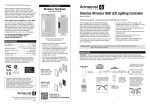
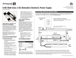
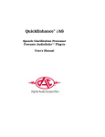
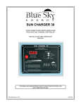
RibbonFlex Pro™ LED Accent Lighting
60 White LEDs per meter (18 LEDs per foot)
Warm Bright White LED Tape Light
Model # RF3528060
Welcome to RibbonFlex Pro™ LED Tape Lighting
Planning
Ultra thin and flexible, RibbonFlex Pro white LED lighting is easy to install in
straight, curved and irregular spaces – offering virtually limitless design and
installation possibilities. Using Everlight™ high performance solid state lighting
technology, light output, color accuracy and LED brightness are exceptional.
Fully dimmable and designed to cast a seamless glow, RibbonFlex Pro creates
warm and relaxing environments or delivers bright task lighting.
RibbonFlex Pro LED lighting is designed for indirect lighting applications. The
light from the LED tape is not to be seen directly by the eye. Every installation
is unique and the illumination effects are personal preference. Installation
location, wall colors, mounting angle, and the light’s reflection off of walls,
surfaces and objects will affect the final lighting appearance.
™
Installation considerations
60 White LEDs per meter (18 LEDs per foot), model # RF3528060
Good, all-around solution for accent lighting and lower brightness task lighting.
■
Where will you locate your power supply?
■
How will you switch your LED lighting on and off?
■
Over, under and inside cabinets, and in toe kick areas
■
What is the best layout configuration for your installation?
■
Indirect lighting for coves and tray ceilings
■
How will you run and conceal the wires to your LED tape lighting?
■
Edge lighting under counters and shelving perimeters
■
Use in displays and bookcases
■
Creative lighting for objects and artwork
Power supply location and voltage drop
The power supply that provides 12V DC power to your LED tape lighting
operates on 120V AC household current. The shorter the wire lead between the
power supply and the LED tape lighting, the brighter the lights will be. If the
lights farthest from the power supply appear dim, it is due to voltage drop.
Please read these guidelines completely before installing.
RibbonFlex Pro LED tape is a new and exciting type of lighting. It is
important to read these guidelines completely to understand how the product
works, and how it can be configured, cut to size, connected, and installed so
you can design your LED lighting layout.
About voltage drop
Voltage drop is a natural occurrence in all low voltage lighting systems. It
is the gradual decrease in voltage that occurs along the length of the 12V
power feed wires to the lighting, and varies depending on the type and
size of the LED tape light installation. It is a function of wire length, wire
thickness, and the energy or total watts used by the lighting.
Installing tape lighting is an easy DIY project, however, basic wiring skills such
as stripping, splicing, extending, and connecting wires are required.
This product operates on low voltage 12V DC power. 12V DC power supplies
are sold separately and are available in different wattages.
Voltage drop only becomes undesirable if you notice the brightness in one area
of your lighting is objectionably different than in another area. As a practical
approach, test your lighting prior to final installation. Refer to the chart below for
recommended lengths of power feed wires using 22 and 18 AWG wires.
Visit armacostlighting.com for additional installation tips and ideas plus
FAQs and latest product information.
Excessive voltage drop = reduced brightness and color accuracy
Shorter and/or thicker wires = higher brightness and color consistency
Longer LED tape = an increase in voltage drop
Recommended maximum length of 12V power wires from power supply to LED lighting
22 AWG WIRE
Cut to Size
Connect with Ease
Peel and Stick
Offers unlimited
lighting design
options for custom
installations.
Use LED Snap
Connectors to join
strips and add
power wires.
Simply remove 3M
backing from LED
tape lighting and
stick in place.
If your LED tape light
length is:
12 Feet
24 Feet
36 Feet
48 Feet
Use only with low voltage 12V DC power source
■
Do not stare directly into the LED lights when illuminated
■
Do not power LED tape while coiled on reel
■
Disconnect power supply before cutting and connecting
■
■
■
If you do not have a switched 120V AC outlet for your LED power supply, consider
an optional Armacost Lighting wireless wall switch or LED dimmer switch.
WALL
SWITCH
SWITCHED
AC OUTLET
12V DC
POWER SUPPLY
WALL
SWITCH
SWITCHED
AC OUTLET
12V DC
POWER SUPPLY
WIRELESS
WALL SWITCH
120V
AC OUTLET
WIRELESS
WALL SWITCH
120V
AC OUTLET
Use only insulated staples, plastic ties, or wire support clips to secure
cords and wires
Route and secure wires so they will not be pinched or damaged
For any wire runs inside of walls, use properly certified CL2 or better cabling
■
TYPICAL CONNECTING AND SWITCHING OPTIONS
Do not install this product in wet locations
■
Max wire length to
tape light
20 Feet
16 Feet
12 Feet
8 Feet
Switching and dimming options
Always observe polarity for 12V connections, positive (+) to positive and
negative (–) to negative
■
If your LED tape light
length is:
12 Feet
24 Feet
36 Feet
48 Feet
For an online voltage drop calculator, visit armacostlighting.com/installation.
IMPORTANT
■
18 AWG WIRE
Max wire length to
tape light
10 Feet
8 Feet
6 Feet
4 Feet
WIRELESS
LED DIMMER
SWITCH
WIRELESS
LED DIMMER
SWITCH
Do not install Class 2 low voltage wiring in the same runs as AC main
power. If AC and low voltage wires cross, keep them at 90-degree angles
WIRELESS
SWITCH
RECEIVER
WIRELESS
SWITCH
RECEIVER
12V DC
POWER SUPPLY
12V DC
POWER SUPPLY
120V
AC OUTLET
12V DC
POWER SUPPLY
LED
DIMMER
120V
AC OUTLET
12V DC
POWER SUPPLY
LED
DIMMER
120V
AC OUTLET
12V DC
POWER SUPPLY
120V
AC OUTLET
12V DC
POWER SUPPLY
WIRELESS
LED DIMMER
RECEIVER
WIRELESS
LED DIMMER
RECEIVER
LED
Interior
RV and FUSE
boat applications can be poweredDIMMER
directly by 12V battery
12V BATTERY
All wiring must be in accordance with national and local electrical codes, low
voltage Class 2 circuit. If you are unclear as to how to install and wire this
product, contact a qualified professional.
12V BATTERY
1
PROTECTION
12V SWITCH
FUSE
PROTECTION
12V SWITCH
LED
DIMMER
Configuration options
Cutting, connecting and wiring
RibbonFlex Pro offers endless connection options to fit virtually any
installation imaginable. LED tape strips can be installed in series (strips
connected or wired end to end) or in parallel (multiple legs of LED strips or
series of strips wired directly to a single power supply).
RibbonFlex Pro is designed for custom lighting installations. Basic wiring skills
such as stripping and splicing wire connections are required.
Always maintain polarity when
connecting LED tape lighting and low
voltage power wires.
TYPICAL CONFIGURATIONS
Be sure to connect positive wires to
positive (+ to +), and negative wires
to negative (– to –). Polarity is easily
identified with + and – marking on
LED tape as shown.
Straight Run
Only one end of the LED strip
is powered. Multiple strips can
be connected in a series for a
continuous run. LEDs farther
away from the power supply may
appear dimmer due to voltage drop,
especially if longer wires are used
in between to connect strips.
POWER
SUPPLY
Positive
Negative
Cut with scissors
This tape light model can be cut every 3 LEDs, or about every 2”. Only cut
tape light in the center of the copper pad locations, “A,” as shown below. If
you cut at a soldered position, “B,” also shown, you may need to remove the
solder from the tape connection joint in order for an LED Snap Connector to
work properly. Solder joint positions are located every 19.7 inches (½ meter).
Center Feed / Loop Back
Either power two equal legs of tape
lighting from the center or loop
back and power both ends of the
LED tape. These configurations will
produce more consistent brightness
and color over the length of the strip.
A loop back is excellent for room
perimeter tray ceiling or cove lighting.
LEG 1
A
LEG 2
B
POWER
SUPPLY
POWER
SUPPLY
LED Snap Connectors make easy, secure solderless connections
Array
Wire Lead Snap Connectors
An array uses two or more legs of
various lengths wired to a power
supply in a parallel connection. You
will need to calculate total wattage
used in an array to guard against
overloading the power supply.
LEG 1
POWER
SUPPLY
Wire Lead Snap Connectors are used for going around corners or, when cut in
half, to create two power leads (“jumper” cables) for linking and extending
power wires to LED tape lighting in other areas.
LEG 2
LEG 3
IMPORTANT: Always use the + / – indicators printed on the tape light to
maintain polarity (+ to +, – to –).
Choosing a power supply
To make longer
“jumper” cables
LED tape lighting power requirements are based on several factors, including
your configuration (chart above), voltage drop, and the length limitations of the
LED tape lighting. Refer to the charts below for the recommended maximum
lengths of LED tape lighting based on your configuration and choose a power
supply rated greater than your needs – you cannot overpower LED tape lighting.
The LED power requirements shown below are based on 100% full power
brightness levels and do not represent every possible installation scenario.
Cut in half to
create two wire lead
connectors that can
be spliced to longer
wires in order to get
power to LED tape
strips in other areas.
To get power from one LED strip to another, you can extend wire leads as shown
below. 22-18 AWG wire should be sufficient for extending wire leads up to 10 feet.
Shorter and/or thicker wires will mean less voltage drop and higher brightness. For
an online voltage drop calculator, visit armacostlighting.com/installation.
(+)
(+)
(+)
Maximum length of LED tape based on configuration type and power supply
Power Supply
Straight Run
Center Feed / Loop Back
6 Watt
3.3 ft (1.0m)
Not recommended
15 Watt
10.5 ft (3.2m)
9.0 ft (2.75m)
30 Watt
24.0 ft (7.3m)*
20.0 ft (6.0m)
60 Watt
24.0 ft (7.3m)*
48.0 ft (14.6m)
(–)
*Length limitations indicated here are based on the inherent limitations of the LED tape due to voltage
drop in a straight run. Exceeding these lengths will cause LEDs farthest from the power supply to
appear dimmer. A higher wattage power supply will not reduce the impact of voltage drop. For more
consistent brightness consider a center feed or loop back configuration.
Due to voltage drop, longer lengths of LED tape will use fewer watts per
foot than shorter lengths. The total watts used in an array layout depend on
the wattage requirement of each leg and overall voltage drop within your
connection wires. A leg can be a single LED strip or series of strips connected
end-to-end. Various legs are wired in parallel directly to the power supply.
Splice Snap Connectors
Splice Snap Connectors are for joining two strips to create a continuous run
of LED lighting.
Calculate the wattage for each leg by multiplying watts per foot by the length
of LED lighting in the leg. Include only the lengths of LED tape in your
calculation, not the connecting wires. Add each leg’s wattage requirement
together to determine the total watts needed to power your array and select
the appropriate power supply.
1 to 5 feet
6 to 10 feet
11 to 15 feet
Watts used per foot
1.8 watts/ft
1.6 watts/ft
1.4 watts/ft
(–)
Wire splice connections: Maintain polarity when extending cables and be
sure all splice connections are secure. Splicing options include crimp
connectors, wire nuts, terminal blocks and soldering wires. Be sure to use
wire connectors that are sized for the wire gauge you are using.
Array power supply calculation
Length of leg (LED tape light only)
(–)
Splice Snap Connector
(+)
(+)
(–)
(–)
If the + / – marks do not line up,
flip the tape and use the opposite
end for proper alignment.
How to use Snap Connectors
Calculate each leg’s wattage requirement separately, then add together for the total
watts needed for your array. Select a power supply that exceeds the total watts needed.
2
■
Pry open lid on the side you wish to connect an LED strip to.
■
Peel back about ¼ inch of the 3M adhesive backing on the bottom of the strip.
■
■
■
■
Above Cabinet Uplighting
Using a side-to-side motion, carefully slide tape strip into connector
channel as shown below so the copper pads on the tape are positioned
underneath the connector contacts.
Most cabinet tops have uneven surfaces. To create beautiful indirect
uplighting over cabinets, simply mount RibbonFlex Pro on any rigid strip
(e.g., thin lattice or corner guard molding) and place on top of cabinets.
Angle the strip position to achieve the desired illumination.
Close and snap down lid connector.
Perform a power test to be sure connection is secure and that all LEDs light
before final installation.
If LEDs do not light, or LEDs flicker, repeat the steps outlined above.
Insert tape in channel
under contact tabs
For a seamless glow and to avoid bright light spots, keep LED tape light strip at
least ¾" away from walls.
You can also solder lead wires to LED tape
Cove Lighting
LED strips can be direct wired by soldering leads onto
the copper pads as shown. Test light connection, then
seal with 3/16" heat-shrink tubing.
CEILING
Installation
Mount LEDs 3/4"
or greater from
wall to avoid
bright spots
Every lighting situation is different. Where you decide to mount and position the
LED tape is a personal preference that will affect the illumination appearance.
Before removing 3M backing tape, test fit and light your RibbonFlex Pro in the
space you intend to install the lighting.
Troubleshooting
Power your LED tape lighting and temporarily hold or tape into position with
masking tape – do not remove backing tape. Move the tape light around and
try various angles and positions to get the desired level of illumination and
lighting appearance. If the LEDs create undesirable light spots on walls, or
reflections, reposition LED tape light strip farther away from surfaces or try a
different mounting angle.
Tape light strip does not light
■ Make sure your LED power supply is turned on and receiving power.
■
Final Mounting
■
Once you have determined your final mounting position, clean the surface
to assure the 3M self-adhesive backing will adhere properly. The mounting
surface needs to be smooth, dry, and free from oils and waxes. Denatured
alcohol or acetone can be used; be sure to read labels carefully as some
solvents can damage certain surfaces.
Confirm you have maintained correct polarity (+ to + and – to –) when
joining LED strips as well as when connecting to the 12V power supply.
Check all tape light connections and any switch or dimmer connections
from the power supply to the LED tape light. Consider testing with a
multimeter to ensure light strip is receiving 12V power.
Only part of the LED tape light strip is lit
Remove the 3M backing from one end and carefully place the tape light
along the surface mount area. Using a cloth, gently press between the LEDs
to help ensure secure contact with the surface. Avoid pressing on the
individual LEDs as this could damage the LED solder connection to the tape.
■
Check connections to the part of the strip that is not lit.
■
Confirm that you have maintained correct polarity to the unlit section.
■
If only 1 LED series is out, cut out and remove the damaged 3-LED group
and splice together LED tape strips or replace with new 3-LED section.
LED tape lights blink on, then go off
Support the 12V
power feed wire
using peel-and-stick
wire support clips
as shown.
■
Your power supply is not adequate for the length of LED tape light you
are powering. Install a higher wattage power supply or reduce watts
used by shortening the lengths of your LED tape lighting.
LEDs farthest from the power supply are noticeably dimmer
■
Although RibbonFlex Pro can be installed in curved and irregular spaces,
avoid sharp bends or bending on the solder joints as you could damage the
LED tape light. If an LED is inadvertently damaged and fails to light, the
remaining LEDs will continue to operate. RibbonFlex Pro is made with 3
LEDs connected as one series. If you experience a failure, you can cut out
and remove the damaged 3-LED series and splice together new LED tape.
■
This is the result of voltage drop. Decrease the length of the 12V power
feed wires or use thicker power feed wires between the 12V power
supply and the tape lighting.
Use shorter lengths of LED tape lighting. Refer to Configuration options
in these guidelines. Consider a different configuration.
Visit armacostlighting.com/installation for additional installation tips and FAQs.
Under Cabinet
To surface mount LED tape lighting under a set of cabinets in one continuous
run, you may need to drill a ½" hole through any cabinet side lip that may be
present. Install LED tape lighting through the hole and surface mount as a
continuous run.
Mounting
too close
to lip may
create an
undesired
shadow
RibbonFlex Pro
has a wide 120
degree beam angle
Limited 3-year warranty
This product is for dry location use only. Improper installation, improper
powering, abuse, or failure to use this LED tape light for its intended purpose
will void warranty. LED tape light cannot be returned or exchanged once cut
unless under warranty replacement. Proof of purchase is required for all returns.
Questions? Email [email protected].
SPECIFICATIONS
Mount inside
of lip for wall
wash effect
Input Voltage.......................................................... 12V DC
LED Count ........................................................ 60 LEDs/m
LED Module .........................................Everlight SMD 3528
Chip Size .............................................................10 x 23μ
Beam Angle ....................................................... 120° wide
Tape Height/Width ................................................ 2 x 8mm
Cuttable......................................... Every 2" approx (50mm)
Lumens Per LED...............................................Approx 7 lm
Color Temperature (CCT)........................................... ~3000
Color Accuracy (CRI) .................................................... ~79
Listings ......................................................CE, RoHS, CSA
COUNTERTOP
When mounting under a cabinet
or a shelf with no lip to hide the
LED tape light strip, create a visual
barrier by using trim strip molding
mounted in front of the LED tape light.
3
140 Baltic Avenue
Baltimore, MD 21225
armacostlighting.com
© 2012 Armacost Lighting.
All rights reserved.
rev 12.12