1
Shallow Well Model Systems
Operating Instructions and Parts Manual
Manuel de Instrucciones y Lista de Piezas
Sistemas de modelos para Pozos Poco Profundos
Para Ordenar Repuestos o Asistencia Técnica, Sírvase Llamar al
Distribuidor Más Cercano a Su Domicilio
1
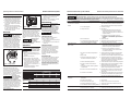
A shallow well pump can be used when
the pump is located within 25 feet
vertically of the water level. Shallow well
pumps have only one pipe between the
pump and the water supply (Figure 3).
DRILLED WELL (FIGURE 13)
1. Install a foot valve on the first section
of pipe (Figure 3, Illustration A).
2. Lower the pipe into the well.
18
2
To Pump
3
4
6
Well
Seal
12
7
5
9
8
Well
Casing
13
10
Foot
Valve
11
16
To
Pump
1
2
3
4
5
6
7
8
9
10
11
12
13
14
15
16
17
18
•
•
•
•
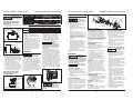
Descripción
Motor
Tornillo
Plato de cierre
Junta cuadrada de goma del anillo
Ensamblaje de sellado del eje
Impulsor
Difusor
32059-001
16636-002
17145-001
17150-001
56393
23285-002
17148-001
Tornillo
Anillo en O
Venturi
Boquilla
19,1 mm (3/4 in.) Tapón de cebado
Volute
6,4 mm (1/4 in.) NPT Tapón de cebado
3,2 mm (1/8 in.) NPT Tapón de cebado
Base
Presostato
Interruptor de flujo
Juego de repuestos (Incluye No. 4, 5 y 9)
67007-001
15557
17151-002
15672
15921
56869-001
16314-002
15766-002
23029-001
30010-001
30048-001
56874-001
Cte.
Packer
Type Foot
Valve
1
1
1
1
1
1
1
1
1
1
1
1
1
1
1
1
1
Shallow Well
Inlet
Outlet
0-25
26-100
1-1/4 in.
1-1/2 in.
2 in.
3/4 in.
1
1-1/4 in.
3. Add pipe until the foot valve is 5 feet
below the lowest anticipated water level.
The foot valve
should be at least 18”
from the bottom of the well or sand or
sediment could be drawn into the system.
4. After proper depth is reached, install
a well seal or pitless adapter to
support pipe and prevent surface
water and other contaminants from
entering well.
5. Slope the horizontal pipe upward
toward the pump to eliminate
trapping air. Sloping the pipe will
also aid in priming the pump.
Drive
Point
Leaking joints or couplings will allow
air to leak into the pipe and cause
abnormal pump operation. Make sure
to use pipe joint compound on all male
pipe threads.
1. Install a foot valve on inlet pipe and
lower into water.
Illustration B
The foot valve should
be at least 18” from
the bottom of the well or sand or
sediment could be drawn into the system.
To
Pump
NOTE: When a lake is used as a water
supply, make sure the inlet pipe is deep
enough to be submerged at all times.
Slope the horizontal piping upward
toward the pump to prevent trapping air.
The pipe must be removed during winter
months or protected against freezing.
Incline
Check
Valve
Drive
Point
100-300
SHALLOW WELL PUMP WITH
CONVENTIONAL STORAGE TANK
(FIGURES 4 & 5)
Prime
Plug
To Suction
Air Volume
Control
Tubing
Pressure
Switch
Air Volume Control
Air Volume
Control Tubing
Hose
Coupling
Outlet
Figure 5 - Vertical Tank
1. Install air volume control on tank.
2. Connect the copper tube from the air
volume control to the uppermost 1/8”
NPT opening on the side of pump. Be
sure the connections are tight. Leaking
can cause the pump not to prime.
3. Install a valve and an isolator hose
between the tank and the house plumbing
to aid in pump removal for servicing and
for reducing the noise transmitted to the
house thrugh the piping.
4. Provide a hose bib (faucet) at the
lowest point in the system to drain
the system for service or storage.
SHALLOW WELL PUMP WITH
PRECHARGED STORAGE TANK
(FIGURE 6)
Priming
Plug
Motor Outlet
Nozzle
Clean
Out
Protect the pipe from damage from
swimmers and boats.
Install a screen
around the inlet pipe
to prevent the entrapment of swimmers.
Illustration C
Air
Volume
Control
Figure 4 - Horizontal Tank
DRIVEN WELL (FIGURE 13)
1. Drive the point several feet below the
water table.
DUG WELL, CISTERN, LAKE AND
SPRING INSTALLATION (FIGURE 13)
Figure 3
30 Sp
Horizontal Distance
(Feet)
As an alternative, an in-line check valve
can be used with a driven well (Figure
3, Illustration C). The pipe between
the check valve and the water level will
always be under a vacuum.
14
15
No.
Repuestos
Pump Model
Pump
Opening
NOTE: A packer type foot valve can
be installed in the well (Figure 3,
Illustration B). This type of foot valve
allows the well to be filled with water
when priming and makes the inlet pipe
much easier to test for leaks. Follow
the manufacturer’s instructions when
installing the packer type foot valve.
Illustration A
17
No. de
Ref.
CHART 2 - PIPE SIZING
SHALLOW WELL INSTALLATION
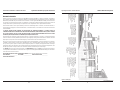
Envíe su solicitud de repuestos a la
siguiente direccion:
WAYNE Pumps
101 Production Drive
Harrison, OH 45030 U.S.A.
Sírvase proporcionar la suguiente información:
- Número de modelo
- Número de serie (si tiene)
- Descripción y número de repuesto como se
muestra en la lista de repuestos
Installation (Continued)
28-30 psi
3/4 HP & 1 HP
Drain
Fitting
Figure 6 - Precharged Storage Tank
3
www.waynepumps.com