1
Gutter Hood Tools & Accessories
New Construction and Retrofit
Now includes 5"& 6" inch gutter installations
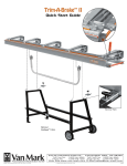
Trim-A-Gutter™ Model TAG50
Shown with Metal Master® 20 Brake and
UniStand™ USA2 Tool Support (each sold separately)
Save This Guide
For Reference!
Table of Contents
Trim-A-Gutter™ Model TAG50
Shown with UniLegs™ UNL1 (sold separately)
Tool Setup, Bending Brakes.............................2
Tool Setup, Metal Master® 20...........................3
Tool Setup, With Unilegs™................................4
Forming Gutter-Hood........................................4
Existing Gutter Installation................................4
Forming End-Caps, Miters, & Valleys...............5
Template...........................................................6
New Gutter Installation.....................................6
Example Profiles/Uses......................................7
Care & Maintenance.........................................7
Parts List..........................................................8
Patent No’s 7,500,375, 7,707,781
Other US and Foreign Patents Pending
Van Mark Web
Price $10.00 US
�������
-2
Tool Setup-Brakes
���� ��������
������� ���
Long Fast Pin 2 ea.
Short Fast Pin 4 ea.
����
����� ��
�
Hex Head Small
10 ea.
Hex Hd Long
4 ea.
��� ��� ������
(L)
Knob 6 ea.
Washer
8 ea.
Locknut
4 ea.
Spacer
2 ea.
��� ��� ������������� � ��������
UniMount™
Assembly
U
se this diagram as a reference for parts/hardware called
out in these next 2 pages, though each part may only be
called out once in each step. Tools needed: Phillips screwdriver, slotted screwdriver and a 7/16 wrench, or socket
wrench.
�����
�������� ������� ���
��� ��� ���� ������ ������
N
ote: Whether mounting your Trim-A-Gutter™ to a Van Mark brake or mounting on optional UniLegs™ for use
with any brake, knowing beforehand which holes in the mounting brackets apply to your particular Trim-A-Gutter/
brake setup will save you time and effort. Please look over the hole locations above and determine which setup below
applies to you before proceeding.
Setup Note: Determine the type of Van Mark brake you use and follow the instructions in that column to mount your new tool. For all other brakes you must purchase a set of UniLegs™ and follow
.
steps 1-6 “Tool Setup on UniLegs” at the bottom half of page 3.
MARK SERIES™ BRAKES
MARK II TRIMMASTER®
TRIM-A-BRAKE I™
������ �������
1
As seen in the mounting bracket above, use holes
O and Q when mounting right bracket K and left
bracket J on either side of the center casting.
1
������
As seen in the mounting bracket above, use holes
O and P when mounting right bracket K and left
bracket J on either side of the center casting.
��������
������ �������
As seen in the mounting bracket above, use holes
1bracket
O and Q when mounting right bracket K and left
J on either side of the center casting.
���������
���������
���������
���� �����
Install &
hook these 2 first
2
Insert hex head screw C down front hole O of right
bracket K. From below, place washer F onto threads
and start hex nut G. Insert hex head screw C down front
hole Q of right bracket K Again place washer F onto
threads and start hex nut G. Place bracket K over rails letting washers F hook over rail flanges (see Detail A).
2
Insert hex head screw C down front hole O of right
bracket K. From below, place washer F onto threads
and start hex nut G. Lower front of bracket over base rail
until washer F catches flange (see Detail B). Insert hex
head screw C down rear hole of O. From below, place
washer F onto threads and start a hex nut G to capture
front base rail.
2
Insert hex head screw C down front hole O of bracket
K. From below, place washer F onto threads and start
hex nut G. Insert hex head screw C down front hole P of
right bracket K. Again place washer F onto threads and start
hex nut G. Place bracket over rails letting washers F hook
over rail flanges (see Detail B).
������ �
��������
��������
Add these 2 next
to capture brake
rails (see detail C)
3
Insert hex head screw C down rear hole O. From below,
place washer F onto threads and start hex nut G. Insert hex
head screw C down rear hole of Q. Again place washer F onto
threads and start hex nut G. As seen in Detail C, rail flanges
should now become be captured. Repeat on other side of center
casting with left bracket J then continue to step 4, page 3.
Install & hook
these 2 first!
Add these 2
next to capture
brake rails
3
Position spacer H between bracket K and rail aligning holes. Insert hex head screws D down holes.
From below, place washers F onto threads and start hex
nuts G to capture rail (see Detail D). Repeat on opposite
side of center casting with left bracket J then continue
to step 4, page 3.
3
Insert hex head screw C down rear hole of O. From
below, place washer F onto threads and start hex nut
G. Insert hex head screw C down rear hole of P. Again
place washer F onto threads and start hex nut G. As seen
in Detail E, rail flanges should now be captured. Repeat
on opposite side of center casting with left bracket J.
3-
Tool Setup-Brakes (cont.)
2”
1 1/
Track
4
Place rail L alongside right bracket K with 5/16” hole to
front of brake. Slide hex head portion of screw D down
track and extend through 2nd hole from end of bracket K
as shown (see center arrow). Start knob F onto threads and
leave loose for now. Repeat this procedure with remaining
rail L and left bracket J.
5
Align front hole in rail L with front hole in bracket K.
Insert Fast Pin A through front hole in rail, then through
bracket. Repeat this procedure with remaining rail L and
bracket J.
6
8
9
Start knob F 2 or 3 turns onto the threads of a hex head screw
D. Slide hex head portion of screw into track of rail L 1 1⁄2”
and leave loose. Repeat this procedure with remaining rail L.
Detail F
Slotted
brackets go outside of rails
7
Ensure left & right rails L are 34 1⁄4” apart to receive
the slotted brackets on bottom of tool. After aligning
the slots with knob threads, slide tool onto rails until slotted brackets are FLUSH with ends of both rails (see Detail
F). Tighten knobs on both sides. Ensure rails and brackets
are positioned squarely on brake then tighten all fasteners,
knobs F and locknuts H securely in place. Check all fasteners and knobs often and tighten as needed.
Install the roller handle over the handle plugs and insert
short fast pins B through holes. Reverse procedure to
remove handles when tool is being stored or transported.
Metal Master ® 20 Setup
1
Brake
Rail Track
Mounting
Rail Track L
Flush
Bracket K
To install the bending leaf handle, align holes in ends of
tube with holes in handle plugs. Insert short fast pins B as
shown.
Flush
Slide two hex head screws C into tracks in bottom
of brake rail. Extend bracket K over screw threads
and tighten with knobs E. Ensure bracket K is FLUSH
as shown. Slide two hex screws C into mounting rail
track L and through holes in bracket K. Tighten firmly
with lock nuts G. Repeat procedure on opposite side
of brake facing away. Note: Use illustration below for
assistance.
2
Start a knob E onto a hex screw C and slide into mounting rail track approximately 2 inches. Loosen slotted
brackets from under tool and slide even with mounting rails
keeping tool centered between the mounting rails. Slide the
slotted brackets over the screws until FLUSH with mounting rails. Tighten knobs E securely. Now tighten lock nuts
G. To remove tool, loosen knobs E and slide off from
mounting rails.
Remove tool from brake before moving or transporting around job site. Do not lean on tool as tipping will
occur causing injury or damage to machine.
Go online or click the link below for
additional Instructions, Tips and How To’s
http://www.van-mark.com/Roofing/TrimAGutt/tag_over.html
3
Firmly tighten all knobs E and lock nuts G. Install the rolling handle and the bending leaf handle to complete the setup of the tool. Check the tool often for looseness and tighten as needed.
Make sure the tool is free from dirt and debris which can damage tool and mar material. Do not lean against tool as tipping or damage can occur. Do not use the reinforcement clip when
working with standard trim coil. Refer to step 4 Forming Gutter-Hood for instructions on using the reinforcement clip to make hood from stiffer gutter-coil material. Note: Except for the
special instructions seen above for mounting Trim-A-Gutter™ to the wider 20" throat brakes, all other instructions should be followed.
-4
Tool Setup on UniLegs™ UNL1
Extended Bracket
Side View
Leg Flare
Rail Assembly
Detail G
Lay out rails L as shown with screw tracks facing up.
Insert the hex head portion of screw D into each track
(see Detail G). With bracket K facing downward, align
holes (indicated by arrows), with hex head threads and
lower into place. Tighten bracket snugly against rails with
locknuts H.
1
Detail H
2
From opposite end of rails, again insert the hex head
portion of screw D into each track. Align holes in
bracket J with hex screw threads and lower into place.
Install locknuts H. Square up assembly and tighten all
fasteners. Ensure all hole locations match those in drawing before proceeding.
3
Position a UniLeg™ at each end of rail assembly with
the extended brackets facing the same direction as the
leg flares (see Side View). Align rail flanges with retainer
hooks on top of UniLegs™ and slide into place (see Detail
H). Note: Ask for help holding UniLegs™ apart during this
step if needed.
Caution: To prevent the tool from tipping during use, always ensure the extended portion of the bracket is facing the same direction as the leg flare (see
step 3 above). Always situate tool on level ground
4
To finish installing the rail assembly, loosen each T
knob and extend latch plates up and over rail flange
(see detail). Tighten T knobs snugly in place. Check T
knobs often and tighten as needed.
5
Insert a hex screw D through the outward hole of the
extended portion of the bracket K. Start a knob F several threads onto the hex screw D and leave loose for now.
Repeat same procedure on opposite side of rail assembly.
6
Align slotted brackets on underside of tool to outside of
extended brackets K and J. Align slots with hex screw
threads and slide in place to a complete stop. Tighten
knobs F snugly. Install handles referring to Steps 8 & 9
above.
Forming Gutter-Hood
Note: General knowledge in the installation of gutters and/or roofing field will be very helpful in using these guidelines. Please take time to read this User Guide before getting
started. In this section, we will show how to form basic gutter-hood from standard trim coil.
1
With finish side of material facing downward, slide
flat end between roller and anvil until the 1/2" flange is
fully seated in notch. Note: The 1/2" flange must be exact
to work properly with brackets.
2
Lift roller handle to a complete stop to form the radius.
Note: When forming standard trim-coil, use of the
reinforcement clip (step 4), is unnecessary.
4
5
6
For gutter-coil, insert blank per Step 2 above and slide
reinforcement clip in place. Lift roller handle to form
radius without allowing blank to touch or hit the clip
which can cause damage to material.
Return roller to the starting position and remove reinforcement clip if in use. Rotate blank and slide from
tool. Note: Practice with smaller lengths until satisfied
with results.
3
Detail
Cut a blank up to 50 inches long and to the desired
width. Insert edge fully into slot with finish side (the
side exposed to the weather), facing as shown. Bend upward 90˚ to create a 1/2" flange.
Cut a 3” or 4” strip and perform steps 1, 2 and 3 above.
This will become your template to use throughout the
job and will be further explained in the following steps
below.
Pre-Installation Note: Most trim/gutter coil comes from the factory with a glossy, or shiny finish which can cause rain to overshoot the gutter opening (similar to
water running off a waxed car). This is a common occurrence in the gutter/leaf protection industry and should be discussed with the property owner. Normally, the
gutter-hood loses it’s shiny finish after a short time of exposure to the elements with the water then wrapping around the gutter-hood and falling into the gutter
trough the way it’s supposed to. One solution, for those who don’t want to wait for Mother Nature to do her thing, is to remove the shiny finish on the gutter-hood
surface by lightly wiping it with a Scotch-Brite® type pad so it dulls the surface slightly. This should allow the water to properly adhere to the gutter-hood until it is
deposited into the gutter trough. Note: Scotch-Brite® is a registered trademark of the 3M corporation.
5-
Existing 5 & 6 inch Gutter Installation
The following instructions are to be used as a guideline on getting up and running with Trim-A-Gutter™ Tools and Hardware. Before getting started, it is recommended that you check the entire gutter system for problems, such as clogged downspouts, leaks or rotted wood, before installing gutter-hood. Use these guidelines
for installing new 6" brackets as well. Check end caps, outlets and seams for water-tightness. Keep in mind Trim-A-Gutter™ gutter-hood will not make the gutter
system waterproof, only leaf resistant.
1
Clear all leaves and debris from gutter and downspouts. Check entire gutter system for loose spikes/seams and miters. Other problem areas, such
as improperly installed gutters and downspouts should be corrected before
installation.
2
Pre install anchor screw into bracket. Near the gutter end-cap, lower
back of bracket into gutter and insert front into gutter channel until hook
catches lip (Detail A). Next, lift bracket until bottom is level. Hold firmly in
place and drive anchor into fascia (Detail B). Note: If loose or no lip exist in
channel, install 3/8 ”stainless screw thru channel and into slot (Detail A).
���
���
���
3
Install second bracket approx. 24” from 1st. Install 3rd bracket 1/2” in
from end of the first gutter-hood section. This bracket will also serve as
the 1st for the next section of gutter-hood which will overlap the 1st (or under
depending upon prevailing wind direction). Note: For extreme weather conditions, install additional brackets.
4
Carefully pinch up the tabs along the course of shingles the gutter-hood
will be going under. To prevent puncturing/breaking the shingle tabs,
work the pinch bar side to side as opposed to up and down. Note: Care
should be given to older shingles which become brittle over time.
BEND LINE
BEND LINE
5
Situate the template into bracket and onto roof area. Mark point in template where you want to match roof pitch (as shown), and make bend. The
area below the bend line must maintain a slight pitch for positive drainage.
6
After forming gutter-hood, transfer bend line from template onto piece.
Place piece into the brake aligning the bend line with the stainless edge.
Bend upward until the piece matches the template to create the first section
of gutter-hood.
Gutter-Coil
Cement
7
Detail
Tuck top of gutter-hood under loosened shingle tabs and fasten 1/2"
flange into first 2 brackets using 3/8" stainless screws (see Detail). Leave
the 3rd bracket free until next section of hood is lapped. Reseal shingles by
applying a bead of roof cement under each tab. Allow tabs to fall back in
place ensuring no roof cement is visible, or exposed.
Detail
8
Lap the next section of gutter-hood over/under the 1st section to a point
where both ends are centered over a bracket. Install the 3/8" stainless
screw thru lap and into bracket. With your template, continue installing
brackets and sections in this manner until complete. Note: When using gutter coil place lap between 2 brackets (see Detail).
-6-
End Cap Template
*To download a splash or end-cap template, go to www.van-mark.com
and navigate to the Trim-A-Gutter™ Installation page. Scroll down and
click either the splash or end-cap image.
�����������������������������
��������������������������������
����������������������������������
����������������������������������
��������������������������������
���������������������������������
����������������������������������
������������������������������
End Cap, Miter & Valley Construction
O
ption 1. Install gutter-hood 2-3 inches past end of gutter. Cut away the nose
portion extending past the end cap. Trim the excess apron to edge of roof. Bend
flap downward 90°, and trim along roof edge.
O
M
V
iter. For hip roofs or returns, trim 1st section 50° and 2nd 45°. Butt the two
sections along miter line. The extra 5° is used to conceal any gap between the
miters and can be bent over to fit the contour of the ridge caps. Slide top edges under
ridge cap. Once satisfied, fasten sections into brackets. Install splash guard* using
3/8" self-drilling stainless screws.
ption 2. Use template* (above), to transfer dimensions onto material. Trim
and bend piece to fit profile. Bend flange 90° and install a 3/8" self-drilling
stainless screw at each end and bottom tab.
alley construction will vary from job to job. For typical installation, run 1st
section past the miter line and trim the next piece even with the miter line.
To prevent water run-off, add a splash guard* as shown using 3/8" self-drilling
stainless screws.
Two common installations for Trim-A-Gutter™ are fascia and roof mount. What style you use will depend on preference and job dimensions. Use these details as a guide
in choosing. Note: It is the responsibility of the installer to ensure work conforms to building code and sound gutter/roof installation practices.
New Gutter Installation-Fascia Mount
1
Hang gutters as you normally would using Trim-A-Gutter™ brackets & anchor
screws. Design gutter-hood to terminate either at the top of fascia with a 90°
flange (A) leaving room for drip edge, or (B), make bend 180° downward leading
into gutter. Create a template of your profile as previously explained. Follow steps
2-8, as they apply, in the Existing Gutter Installation section.
2
Next, install drip edge, underlayment and roofing per manufacturers instructions. Note regarding miters and end-caps: Due to the wide range of applications seen in residential gutters and roofing, it would be virtually impossible to
outline detailed steps for making and installing them all here. We recommend
using scrap to make practice bends until you are satisfied with your results.
7-
New Gutter Installation-Roof Mount
Detail
Bend Line
L
D
ow Profile. Install gutters using brackets & anchor screws. Create a template based
on this profile remembering to keep a downward pitch from the bend line to the nose.
Install drip edge and underlayment, then sections of gutter-hood based on your template.
Install shingles even with bend line. Note: You may install hood under the 1st course of
shingles provided the gutter is low enough to maintain the downward pitch from the bend
line to the nose.
ome Profile. Install 1st course of shingles. Determine whether gutter-hood will
go under the 2nd or 3rd course of shingles. Create a template of this profile and
mark your bend line as previously described. With this particular design being more
visible , match the gutter color as closely as possible for seamless integration.
Example Side Elevation
Common Roof/Gutter/Fascia Profiles
�������
�������
��������
���� �����
������������
�������
���� ����
��������� �����
������
�������
3/12 Pitch-Under Shingle
3/12 Pitch-Over Shingle
������
���� ������
������
������ ����
�����������������������
6"
Gutter
�����������
12/12 Pitch-Over Shingle
12/12 Pitch-Fascia Mount
���������
����������
8/12 Pitch-Over Shingle
18/12 Pitch-Mansard
1. Insert blank 1/2" into brake, lock in place. Bend 130° (max. bend on brake).
2. Remove from brake, turn around and reinsert to 3/4", lock in place. Bend 90°.
3. Unlock brake and slide out 3/4", and re lock. Make bend 30°.
4. Unlock brake and slide out approx. 3". Make bend 60°.
5. Unlock & slide out approx. 3.5 to 4". (to achieve 5" bracket span). Bend 90°.
Care & Maintenance
Your new Van Mark tool has been calibrated and adjusted at the factory and is ready to go. Follow these steps for optimum performance and installation of gutter-hood.
The Trim-A-Gutter™ TAG50 Tool
Installation Tips
1. When mounting to your Van Mark brake, always ensure brake is level on stable footing.
2. Never lean or place weight on tool once mounted as tipping can occur.
3. Keep bending leaf hinge and slot free from debris (no. 17 & 23 on your parts list).
4. Always remove tool from your brake before transporting to and from the job site.
5. Check all fasteners and knobs often and tighten as needed.
6. Clean and lubricate tool with light spray-lubricant before use, or as needed.
7. Keep hands and fingers away from moving parts while setting up and using tool.
8. Never expose tool to rough loading/unloading, bumps and knocks as damage will occur.
9. For balance, always mount tool as close to the center of the brake as possible.
1. For best results, use a screw gun with adjustable torque settings.
2. Pre install anchor screw into bracket until barely visible out the back.
3. Hold bracket firmly in place while driving anchor screw into fascia.
4. Do not over-torque anchor screws and cover screws which can twist off heads.
5. Do not set ladders against nose of gutter-hood as slipping or damage can occur.
6. Ensure you have adequate amount of brackets and anchor screws before starting job.
7. For added durability and strength, increase the amount of brackets per section.
8. Form gutter-hood blanks (without the roof pitch bend), at the shop between jobs.
9. Download & print sales literature from Van Mark’s web site for customer presentations.
Although Van Mark undergoes extensive research on all our products, including the Trim-A-Gutter™ gutter-hood forming tool, it is the sole responsibility of the user for
the correctness of installing gutter-hood to any gutter, fascia and/or roofing system, whether new or retrofit construction. Use the instructions provided here, including the
following profiles, as an example on getting started with Trim-A-Gutter™. Van Mark cannot be held liable for any damages arising from the installation of gutter-hood,
hardware, gutter, fascia and/or roofing. As with other Van Mark tools, we recommend that you make practice shapes with scrap until satisfied with your results.
Trim-A-Gu�er™
Parts List
Effective 11-15-11
For Quick “Same Day Shipment” Order Early
Order Toll-Free 24 Hrs Call Free 1-800 Van Mark Fax Free 1-888 Van Mark
Ref
Qty
Part No
Ref
Qty
Part No
Ref
1
End Block Screw
Description
8
2067
21
Roller Handle
Description
1
4053
40
UniMount™ Assembly
Description
Qty
Part No
1
2
Anvil Lock Screw
4
2014
22
Roller Handle Grip
1
4625
41
1/4-20x5/8 Hex Hd
3097
13
3
Anvil Bracket Screw
1
2010
23
Bending Leaf
1
4620
42
1/4-20x1 1/4 Hex Hd Cap
2058
4
4
Lower Rail Screw
2
2064
24
Leaf Handle
1
4622
43
1/4" Nyloc Nut
2071
16
5
Roller Tube Bearing
2
4604
29
Bending Leaf Stub
2
4623
44
2313
Lock Knob
4
6
Roller Support Bearing
1
4605
30
Roller Handle Stub
2
4110
2072
45
1/4" Flat Washer
8
7
Support Bearing Screw
1
2049
33
Anvil Spacer
2
2512
4631
46
5/16 x 21⁄2" Fast Pin
2
8
1/4 x 1" Fast Pin
4
2710
34
Leaf Handle Grip
2715
1
4626
47
3" Right Body Bracket
1
4632R
9
4632L
Stainless Steel Anvil
1
4606
35
Bearing Brkt. Screw
1
2053
48
3" Left Body Bracket
1
10
Roller Tube
1
4608
36
5/16" Flat Washer
2
2505
49
Rail
2
4634
11
End Block
2
4610
37
Roller Stub Screw
2
2006
50
Right Bracket
1
4633R
12
Pivot Block
2
4611
38
Leaf Stub Screw
2
2070
51
Left Bracket
1
4633L
13
Lower Rail
1
4612
39
5/16" Lock Washer
2
2504
52
Spacer
2
4635
14
Roller Axle
1
4614
41
1/4-20x5/8 Hex Hd
36
2058
15
Bearing Bracket
1
4617
16
Reinforcement Clip
1
4616
17
Body
1
4618
18
Name Plate
1
4628
PN4637
6" Bracket
Available in 100 and 500 pc kits
PN4630
5" Bracket
Available in 100 and 500 pc kits
PN2069
3" Anchor Screw
Available in 100 and 500 pc kits
PN2068
Cover Screw
Available in 100 and 500 pc kits
PN4629
Bit Driver
UniLeg™
Supports
Trim-A-Gutter™ TAG50
Scan with Smart Phone
VAN MARK PRODUCTS CORPORATION
24145 Industrial Park Drive,
Farmington Hills, MI 48335-2864
Michigan 1-248-478-1200
Call Free 1-800-VAN-MARK (1-800-826-6275) Fax Free! 1-888-VAN-MARK (1-888-826-6275)
Web Site: http://www.van-mark.com
E-mail: [email protected]
Note: Price subject to change without notice. Call for current prices before quoting.
Trim-A-Gutter.indd User Guide 16 msd/ee 013012
© 2012 Van Mark Products Corp.
Trim-A-Gutter™ Online
F585