1
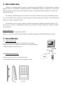
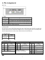
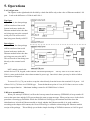
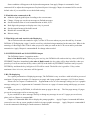
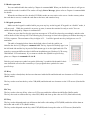
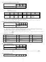
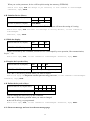
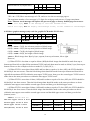
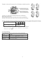
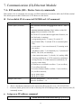
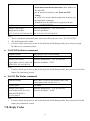
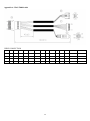
FAT800A Manual Version 1.0 Table of Contents 1.Information 2.Introduction 3.Installation 4.Pin Assignment 5.Operations 6.Communication (I)-Internal Commands 7.Communication (II)-Ethernet Module 8.Specifications Appendix A.WAS-T0090 cable 1 1. Information 1-A. Model Classification: FAT 800A M - 00 1 2 3 4 ○ ○ ○ ○ This device complies with Part 15 of the FCC . Rules. Operation is subject to the following two conditions: (1) This device may not cause harmful interference, and (2) this device must accept any interference received, including interference that may cause undesired operation. 1 Model name: ○ FAT 2 Model number: 800A ○ 3 Reader: ○ M MAG TK2 B barcode reader, LED type F barcode reader, IR type R RFID (125KHz) reader MF Mifare (13.56MHz) reader None without reader 4 Type: 00 standard ○ 1-B. Accessories a. WAS-1499 for LAN cable. b. Bracket and screws package for wall-mount installation. c. WAS-T0090 (optional) for extend I/O d. Disk 5168 including manual file 1-C. Features 122*32 dots, STN, Positive, Reflective, Yellow green graphics LCD LCD Active View Area 53.64*15.64 (mm) Built-in with 12 pages text messages to display 32 ASCII characters each page and serves as a shortcut display Built-in with 6 pages graphic messages to display 122* 32 dots and severs as a shortcut display Able to accept the commands sent from the server to LCD to display the real time message Capable of displaying the alternative customized texts or graphics Capable of blinking display messages in eye catching Able to control the beep pattern in buzzer Auto saving all modified parameter values and start the boot-up status from memory once the device is powered up Available for desktop and wall mount usage Equipped with RJ45 comport which is able to apply with your company’s Ethernet LAN and supports TCP/IP, UDP … protocol. 20 programmable keys and each key can be programmed with the user defined value Options of readers for different applications 4 general-purpose I/O design Supports duplex serial RS232 for a serial printer Able to work with standard PS/2 Keyboard or Barcode device as a extended input devices 2 2. Introduction FAT800A is a terminal which is capable of communicating with SERVER or terminals based on 10Base-T Ethernet network. The FAT800A is equipped with the so-called Ethernet module, a module able to convert the Ethernet package to serial signal stream. All these streams are transmitted to MCU themselves to make each command in control. The software called DS manager and Connection wizard are bundle with the physical FAT800A itself to serve as the utility tools to enable you to get the shortcut of further setting up of creating a virtual COM Port to enable you send the command to MCU. The alternative way is to apply winsock for further development of Ethernet application software. The must you have to know is to understand the data format of Ethernet package and the ones of Ethernet module inside FAT800A. Chapter Reference: Chapter 6 content: the command list of MCU. Chapter 7 content: the details of data format between Ethernet package and FAT800A Ethernet module. 3. Installation 3-A. Connection in LAN a. Connect the cable (WAS-1499) to the RJ45 port of the hub. b. Plug in the DC power adaptor to the power jack on the FAT800A. c. Plug the adaptor to the power line. 3-B. Wall-Mount installation a. Place the bracket on the wall (4 hooks on top). b. Put FAT800A on the bracket, like the diagram as below. 3 4. Pin Assignment Back View 4-A. RJ45 Pin# Signal 1 TX+(Positive line of the differential output signal pair) 2 TX- (Negative line of the differential output signal pair) 3 RX+ (Positive line of the differential input signal pair) 6 RX- (Negative line of the differential input signal pair) 4,5 short connection & 7,8 short connection 4-B. Status LED The green (EG) and red (EY) LEDs represent the status of the Ethernet port. The EG is normally ON, and will temporarily turn off when the FAT800A receives a network packet. The EY is normally OFF, and will temporarily turn on when a data collision is detected on the Ethernet. 4-C. DC power jack Pin# Signal Center (D2.1mm) +9V~+12VDC Outer GROUND 4-D. Dual Box Header KB interface Pin# Signal 1 +5V 3 Serial interface Color (WAS-T0090) Color (WAS-T0090) Pin# Signal Color (WAS-T0090) 9 RxD BLUE 2 +5V RED GND BLACK 11 TxD GRAY 4 GND BLACK 5 CLOCK YELLOW 13 GND BLACK 6 I/O1 ORANGE 7 DATA BROWN RxD(Input), to FAT800A. TxD(Output), from FAT800A 8 I/O6 GREEN 10 I/O7 PURPLE 12 I/O8 WHITE Note. RED Pin# Signal I/O interface The extended serial interface is disabled when reboot and is effected once you set I/O0=0 to enable it. 4 5. Operations 5-A Configuration The figures on the right hand side divided by a dash line differ only at the value of Ethernet module’s I/O port. Look at the difference of I/O0=0 and I/O0=1. Top figure When I/O0=0, the data package will be transferred into serial format in advance inside the Ethernet module before the data are being sent out to the external serial port. This will avoid of data being sent directly to MCU. Down figure When I/O0=1, the data package will be transferred into serial format in advance inside the Ethernet module before the data are being sent out to the MCU. This will avoid of data being sent directly to the external serial port. MCU mainly controls the main 4 devices LCD, keypad, reader and the external keyboard port. The key issue is to set the value at I/O0=1 (same as the default value when terminal is power up). Once this is done you may be able to follow instructions of chapter 6. To access I/O 1,6,7,8 you need to set up the value directly from the host to the terminal’s I/O ports. All of these I/O 1,6,7,8 lines are of CMOS type. From the hardware point of view, all I/O lines can serve as the input or output function. Maximum loading current for all CMOS lines is 10mA 5-B Power up and Reboot When you start up FAT800A, it will set the boot-up status from memory (EEPROM). A beep sound will react at the same time and the LCD screen shows the start-up page message. What you have now is the whole procedure of booting up FAT800A. While the FAT800A is booting up, the terminal itself also does the initialization to its built-in Ethernet module to check whether the Ethernet module is in good condition according to the chapter 4-B content, the Green LED will give a blink to acknowledge the Ethernet module receipt of the package. This will help you with the simple checking of FAT800A connects to LAN in good 5 status. You have to establish the connection with FAT800A again on Ethernet network at every time of reboot. This can be done automatically by the application software from SERVER. When you power up, you will get the I/O0=1 and FAT800A stays at the stand-by mode. Now you are able to give a command to FAT800A. The FAT800A will reply an “ ACK” or a related message as a positive feedback or it will react a “ NACK”. Also be noted that the keypad and reader are enabled while the terminal is power up. 5-C Operation Parameters Setting and obtaining the value Applying command 6-A to get the firmware and current status of the operation parameter on FAT800A. We suggest you use this command to get the current version and correspondent operation parameter settings between server and FAT800A. Chapter 6 Command 6-A will send a “ byte” as the feedback to stand for its current status. You may use the bit to review the buffer/un-buffer mode, asterisk/digit displaying, wall-mount/desk-top viewing, external KB port enable/disable, reader enable/disable, keypad enable/disable, internal serial baudrate, ….etc values. Applying command 6-G to set up the values Chapter 6 Command 6-G severs as the command of values setting up. All settings are saved in FAT800A memory (excluding reader and keypad). While you power up FAT800A, it will always take the last setting from the terminal. 5-D Desktop and Wall-mount usage FAT800A is designed for available for two types of installation (Refer to right hand side figure for easy identification), Desktop operation or Wall-mount operation. But even you have referred to the figure at 3-B for terminal installation of wall mounting, two more issues you have to complete. 1. Sending out the right command 6-G (value m=5, n=0) for first usage when the FAT800A is connected and gets the ACK. 2. Make FAT800A save this setting and is able to reset by itself for every power up. The reason why above issues should be done is if you follow only the instruction of the figure at 3-B you only get the picture of upside down viewing. The message supposed to read from left to right of desktop type will change to read from right to left totally in unreadable arrangement. To avoid this you need to set up the Chapter 6 command 6-G (value at m=5, n=0) to get the correct arrangement reading from left to right as always. Once you change the LCD viewing arrangement, the FAT800A will adjust accordingly while reboot the terminal. 6 Same condition will happen to the keyboard arrangement. Just apply Chapter 6 command 6-J and command 6-K to adjust the arrangement of keyboard layout. Also apply Chapter 6 command 6-H to set the default value if you would like to use the default setting. 5-E Initialization commands (6-H) Make the right keypad layout according to the current status Change 12-page pre-saved text messages to Default messages Set the internal value of serial communication at 9600, N,8.1. Real digit code prompts on display once a key is pressed Set the output format of the buffer mode Disable the external KB port Reboot setting 5-F Real digit code and Asterisk code Displaying The so-call asterisk code stands for sign (*) on the LCD screen when you press the said key. It means FAT800A LCD displaying a sign (*) and in a real key code data being transmitted at the same time. What is the meaning of a Real digit code? That is what you press is what you read on the LCD screen and keycode data transmission. Apply Chapter 6 command 6-G for change when needed. 5-G BUFFER-MODE and NON-BUFFER Output The FAT800A features 2 operation modes. One is Non-Buffer mode. When you press one key, the FAT800A will send out the key value (ASCII) by ETHERNET interface immediately, the other is Buffer mode; the key value will be kept in buffer, when you press keys. It will not send out all key values (ASCII) in the buffer by ETHERNET interface until you press ENTER Key and then the key-in digits on LCD will be erased. The buffer size is good for 32 key values maximum. Once it is over, extra ones will be ignored. 5-H LCD displaying For a quick presentation of displaying message, The FAT800A is easy to achieve with its built-in pre-saved maximum 12-page text messages (32 characters per page) and 6-page graphic messages (122*32 dots) feature. Please refer to Chapter 6 command 6-B. Argument m serves as a text message setting (m=0) or a graphic message setting (m=1). Argument n in Commend 6-B serves as a page of content setting which page you want to exhibit. When you power up FAT800A, it will take the start-up page to show up. The first page among 12-pages pre-saved text messages refers to start-up page. If you would like to show message directly or change any message in one of 12-pages pre-saved texts, please refer to Chapter 6 command 6-L. Chapter 6 Command 6-M is able to display the prompt graphics. Apply Chapter 6 command 6-N when you need to save the on screen graphics in built-in 6-pages graphic messages. Apply Chapter 6 commend 6-I to set the command of blinking to catch customers’ attentions. 7 5-I Reader operation You can enable/disable the reader by Chapter 6 command 6-D. When you disable the reader, it will get no action till the reader is enabled. The reader will reply Notice Message, please refer to Chapter 6 command 6-O for details. When the card data can’t be decoded, FAT800A sends an error notice to the server. On the contrary when the card data is correct, it sends the card data to the host, and sounds a beep. 5-J Keypad operation Make sure the keypad is enabled while you press any key on the keypad. If keypad is at “disable” mode, it will not work. While the terminal is at power up state, it means the terminal is ready to work. You can enable/disable keypad by Chapter 6 command 6-E. When you press the first key, the previous message on LCD will be cleared up accordingly, and the value will be shown on the left-top side. The following key-in message is from left-to-right top-to-bottom showing on LCD by sequence. The maximum of key-in digits is 32. It will be ignored once key-in digits are over 32 maximum. The table of mapping below shows the default value of each key while you initialize the device by Chapter 6 command 6-H. The key layout for Desktop type is on the left hand side and the key layout for Wall-mount type is on the right hand side. The same key represents different value in different installation type (Desktop: LCD on top, Wall-Mount: LCD on bottom). If you want to redefine the Symbol on specific key, please see Chapter 6 command 6-J & 6-K. Each key only maps one symbol except the following 3 symbols which stand for their own definitions served as the control keys if you program these symbols for some specific keys. KeyPosition Coordinate CLR key The key used to clear(delete) the last one character inside buffer and backward one character on LCD screen (Buffer mode) The key used to send out the key value CLR(08H) and backward one character on the LCD screen (Non-buffer mode) ESC key The key used to clear up all key values on LCD screen and delete all data inside Buffer (Buffer mode) The key also used to send out the key value ESC(1BH) and clear up the value on LCD (Non buffer mode) ENT key The key used to dispatch(send out) all data on the buffer with ending of ENT(0DH) and delete all the data on the buffer and on the LCD. (Buffer mode) The key used to dispatch out the key value ENT(0DH) and clear up the value on LCD screen (Non-buffer 8 mode). Default Table of Key Position and Symbol mapping Desk-top Key Layout Wall-Mount Key Layout 1 6 ESC 1BH 2 A 41H 7 1 31H 3 8 4 B 42H 3 33H 13 5 35H 9 7 37H 16 12 2 32H 4 34H 5 11 6 36H 14 8 38H 9 39H 1 C 43H 17 ENT 0DH 2 D 44H 18 7 3 8 4 9 D 44H 0 30H CLR 08H 1 ESC 1BH 7 37H 18 5 35H 4 34H 14 3 33H Symbol ASCII 17 8 38H 13 6 36H Key Position 16 12 9 39H E 45H F 46H 11 . 2EH F 46H E 45H 19 6 19 2 32H 1 31H The text in red bold font (1~20) is used for the absolute position of Key on this keypad. The text in black bold means the Symbol, and the Italic text means the ASCII code in HEX of Key respectively. If you have already key-in some keys and then stop key-in over 10 seconds, FAT800A will erase all keys 10 CLR 08H 0 30H 15 . 2EH 20 ENT 0DH 5 10 C 43H B 42H 15 20 A 41H ESC 1BH on LCD and buffer and issue a timeout notice to host (refer to Paragraph 6-O). Host can erase LCD and buffer by Paragraph 6-C command. When 2 keys or more are pressed simultaneously in vertical direction, none data will be sent out; two more keys pressed simultaneously in horizontal direction, the data of the smallest key position value among of the two more keys will be transmitted accordingly. 5-L External PS/2 KB port Apply command 6-G to enable the external PS/2 keyboard, value is set to m=5, n=1 to enable the extended keyboard functioning. When the said keyboard is enabled, it will send key scan code via standard PS/2 KB communication port; the buzzer of FAT800A reacts a beep sound and transforms the key scan code into ASCII to dispatch out. 9 6. Communication (I)-Internal Command Command symbols definitions are as below: STX 02H ETX 03H ACK 06H NACK 15H m 1 byte parameter n 1 byte parameter <Data…> contents of data (command list) Command Hexadecimal Format Description V STX V ETX Get device firmware version & status D STX Dmn ETX Show pre-saved message page on LCD C STX C ETX Erase LCD and buffer M STX Mn ETX Enable/Disable reader K STX Kn ETX Enable/Disable keypad B STX Bn ETX Control beep P STX Pmn ETX Change operation parameters @ STX @ ETX Initialize device F STX F ETX Blink the display I STX I n ETX Inquire the keycode of key X STX X m n ETX Define the keycode of keys Y STX Y n <Data…> ETX Show text message and save it to the text message page Z STX Z <Data…> ETX Show graphic message S STX Sn ETX Save currently viewing as graphic message page 10 6-A. Get device firmware version & status HOST to DEVICE (3 bytes) DEVICE to HOST (10 bytes) XXXX: V: S: STX V ETX 02H 56H 03H “ROMXXXXV S” Firmware Number Revision Status (8 bits as below) B7 B6 B5 B4 B3 B2 External KB Viewing Keypad Reader Display Mode 1:enable 1:Desktop 0:disable 0:Wall-Mount 1:enable 0:disable 1:enable 0:disable 1:asterisk 0:normal 1:buffer 0:unbuffer B1 B0 Baudrate 00: 01: 10: 11: 2400bps 4800bps 9600bps 19200bps You can get device information and status by this command. You will get nothing, if the computer’s baudrate didn’t match with the device. 6-B. Show pre-saved page message on LCD HOST to DEVICE (5 bytes) DEVICE to HOST (1 bytes) STX D 02H 44H bin bin 03H m n ETX ACK/NACK m: text page message, m=30H; graphic page message, m=31H n: page number, 31H<=n<=3CH(for m=30H, text page); 31H<=n<=36H(for m=31H, graphic page) You can show page message, which is kept in EEPROM, on your LCD. Device will reply ACK and display the pre-saved message, if this command is acknowledged. Otherwise, reply NACK. The default text page table Page# Message Page# Message Page# Message 1 Welcome 5 Card error 9 Verify fail 2 Enter PIN 6 Press ENT 10 Re-enter PIN 3 PIN error 7 Time out 11 Thank you 4 Swipe card 8 Please try again 12 Not working 6-C. Erase LCD and buffer HOST to DEVICE (3 bytes) DEVICE to HOST (1 bytes) STX C ETX 02H 43H 03H ACK/NACK You can clear all screen and buffer by this command. Device will reply ACK, if this command is acknowledged. Otherwise, reply NACK. 6-D. Enable/Disable reader HOST to DEVICE (4 bytes) STX M n ETX 11 02H DEVICE to HOST (1 bytes) 4DH bin 03H ACK/NACK n=31H, Enable reader(default) n=30H, Disable reader Device will reply ACK, if this command is acknowledged. Otherwise, reply NACK. Note: Reader is always enabled when the unit is restarted even though you did disable the reader last time. 6-E. Enable/Disable keypad HOST to DEVICE (4 bytes) DEVICE to HOST (1 bytes) STX K 02H 4BH Bin 03H n ETX ACK/NACK n=31H, Enable keypad(default) n=30H, Disable keypad Device will reply ACK, if this command is acknowledged. Otherwise, reply NACK. Note: Keypad is always enabled when the unit is restarted even though you did disable the keypad last time. 6-F. Control beep HOST to DEVICE (4 bytes) DEVICE to HOST (1 bytes) STX B 02H 42H bin 03H n ETX ACK/NACK n: beep string, composed of 0and 1. Each 1 will activate buzzer, 0 will stop buzzer. Each bit control buzzer 0.1 sec. For example, n=F5H (11110101), it sounds like “BBBB-B-B”. Device will reply ACK and beep, if this command is acknowledged. Otherwise, reply NACK. 6-G. Change Operation parameters HOST to DEVICE (5 bytes) DEVICE to HOST (1 bytes) STX P 02H 50H bin bin 03H m n ETX ACK/NACK Parameter description as below; Change Baudrate Change Mode Change Displaying Type Change Viewing Change Ext.KB (m=31H) (m=32H) (m=33H) (m=34H) (m=35H) n=30H, 2400bps n=30H, unbuffered mode n=30H, normal(*) n=30H, wall-mount n=30H, disable(*) n=31H, 4800bps n=31H, buffer mode(*) n=31H, desk-top(*) n=31H, enable n=31H, asterisk mark n=32H, 9600bps(*) n=33H, 19200bps The (*) means factory default 12 When you set the parameter, device will keep this setting into memory (EEPROM). Device will reply ACK and change as you selected, if this command is acknowledged. Otherwise, reply NACK. 6-H. Initialize Device (Reset) HOST to DEVICE (3 bytes) DEVICE to HOST (1 bytes) STX @ ETX 02H 40H 03H ACK/NACK Host sets all settings into device as factory default. The key layout will meet the setting of viewing. Device will reply ACK and reset all settings to factory default, if this command is acknowledged. Otherwise, reply NACK. 6-I. Blink the display HOST to DEVICE (3 bytes) DEVICE to HOST (1 bytes) STX F ETX 02H 46H 03H ACK/NACK Display will blink by this command, until the device is interrupted by next operation, like communication, key-in, …etc. Device will reply ACK, if this command is acknowledged. Otherwise, reply NACK. 6-J. Inquire the keycode of key HOST to DEVICE (4 bytes) DEVICE to HOST (1 bytes) STX I 02H 49H Bin 03H m ETX KeyValue of specific key position/NACK 01H<=m<=14H, the key position where you want to inquire. Device will reply the KeyValue of the specific key position, if this command is acknowledged. Otherwise, reply NACK. 6-K. Define the keycode of keys HOST to DEVICE (5 bytes min.) STX X m n ETX 02H 58H bin bin 03H DEVICE to HOST (1 bytes) ACK/NACK You can change the code of key by this command. 01H<=m<=14H, the key position where you want to changed. n, the ASCII of key you programmed. Device will reply ACK, if this command is acknowledged. Otherwise, reply NACK. 6-L. Show text message and save it to the text message page 13 HOST to DEVICE (5 bytes min.) STX Y n <DATA…> ETX 02H 59H bin <DATA…> 03H ACK/NACK DEVICE to HOST (1 bytes) n=30H, Show text message to LCD, but never keep it. 31H<=n<=3CH, Show text message to LCD, and save it to the text message page n. The maximum number of text message is 32 digits for each page and can save 12 pages maximum. Note: This new saved message will replace the pre-saved page or factory default page for next use. Device will reply NACK if the message is over this maximum value. Device will reply ACK and display this message on LCD, if this command is acknowledged. 6-M. Show graphic message (only work for graphic LCD model 122*32 dots) HOSTDEVICE STX Z XPOS YPOS XLEN YLEN <DATA…> ETX 02H 5AH bin bin bin bin <DATA…> 03H DEVICEHOST ACK/NACK Note: This command only works with graphic LCD models 00(H)<=XPOS<=79(H), the left-most position of block image 00(H)<=YPOS<=1F(H), the top-most position of block image. 01(H)<=XLEN<=7A(H), the length of block image. 01(H)<=YLEN<=20(H), the height of block image <DATA…>, Block image data. Byte by byte, sequent, from top to bottom, left to right. However, (1) When YLEN is less than or equal to 8 dots (08H),the block image data should be made from top to bottom and from left to right till the maximum XLEN, and each data must be made as 8 bits(1 byte) from top to bottom. Please see the example as below to make D (1), D(2), D(3),…. (2) When YLEN is more than 8 dots (08H) and less than or equal to 16 dots (10H), the YLEN should be divided by 8 into two sectors. Then the block image data should be made from top to bottom and from left to right till the maximum XLEN within the most upper YLEN sector, then go to the second upper YLEN sector to make data as the same procedures as within the most upper YLEN sector. (3) When YLEN is more than 16 dots (10H) and less than or equal to 24 dots (18H), the YLEN should be divided by 8 into three sectors. Then the block image data should be made as the same procedures as above within the most upper sector and the second upper sector and then go to the third upper sector. (4) When YLEN is more than 24 dots (18H) and less than or equal to 32 dots (20H), the YLEN should be divided by 8 into four sectors. Then the block image data should be made as the same procedures as above within the most upper sector and the second upper sector and the third upper sector and then go to the last (bottom) sector. <DATA…> matrix such as: The most upper sector 8 dots D(1) D(2) D(3) … D(XLEN) Second upper sector 8 dots D(1XLEN+1) D(1XLEN+2) D(1XLEN+3) … D(1XLEN+XLEN) Third upper sector 8 dots D(2XLEN+1) D(2XLEN+2) D(2XLEN+3) … D(2XLEN+XLEN) Last(Bottom) sector 8 dots D(3XLEN+1) D(3XLEN+2) D(3XLEN+3) … D(3XLEN+XLEN) 14 Example: we draw an Euro sign at (8,9) of the display coordinative position. After this, we send sequent command to the device as following, STX, Z, 08H, 09H, 0EH, 10H, 80H, C0H, F0H, FCH, CEH, C7H, C3H, C3H, C3H, C3H, C3H, 47H, 0EH, 04H 04H, 06H, 1FH, 7FH, E6H, C6H, C6H, C6H, C6H, C2H, C0H, E0H, 70H, 20H, ETX 6-N. Save currently viewing as graphic message page(only work for graphic LCD model 122*32 dots) HOST to DEVICE (4 bytes) DEVICE to HOST (1 bytes) STX S 02H 53H bin 03H n ETX ACK/NACK 31H<=n<=36H, Save currently viewing as graphic message page n. Device will reply ACK if this command is acknowledged. Otherwise reply NACK. 6-O. Notice Message Notice Message is Device to send a notice to host automatically. Events Message Card read OK <STX>+<S>+<TK data bytes>+<ETX> Card read error <STX>+<E>+<ETX> Time out <STX>+<O>+<ETX> 15 7. Communication (II)-Ethernet Module 7-A. EM module (DS - Device Server) commands EM contains a lot of commands, but just only 4 of EM commands are needed to utilize the FAT800 terminal. The default protocol that FAT800 uses is TCP. Below are the details. Get available IP of connected FAT800 on LAN command Command format: A. X Possible replies (network): Annn.nnn.nnn.nnn.nnn.nnn/ppppp/mseic/ES/oo...o/dd...d, where nnn.nnn.nnn.nnn.nnn.nnn- MAC-address of the DS ppppp- data port number of the DS m- fixed to 'N' (means that the application firmware, not the NetLoader is running) s- programming mode: '*' (none), 'S' (serial), 'U' (out-of-band UDP), 'T' (inband TCP or command-phase TCP); e- error status: '*' (no errors detected), 'E' (running in the error mode); i- IP-address status: '*' (not obtained yet), 'I' (obtained via DHCP), 'M' (fixed, set manually); c- data connection status: '*' (closed), 'A' (sending ARP), 'O' (being established), 'C' (TCP connection established or being closed), 'U' (UDP connection established), 'R' (reset by remote host); E- Ethernet-to-serial buffer overflow: '*' (no overflow), 'E' (overflow detected); S- serial-to-Ethernet buffer overflow: '*' (no overflow), 'S' (overflow detected); oo...o- owner name; dd...d- device name. Example (VB6 Code) Winsock1.RemoteHost = “255.255.255.255” Winsock1.SendData = “X” Note: 1. This is a broadcasts command, so the remote host IP needs to be set to “255.255.255.255”. 2. For more details, please refer to the on-line help file of DS Manager tibbo_docs.chm on [Echo (X) command] section. Assign new IP-address command Command format: B. Ammm.mmm.mmm.mmm.mmm.mmm/pp...p/iii.iii.iii.ii 16 Where mmm.mmm.mmm.mmm.mmm.mmm- MAC-address of the target DS pp...p- password (defined by the Password (PW) setting) m- fixed to 'N' (means that the application firmware, not the NetLoader is running) iii.iii.iii.iii- new IP-address to be assigned to the DS Possible replies: A, D, C, F (see Reply Code section) Example (VB6 Code): Winsock1.RemoteHost = “255.255.255.255” Change the IP of MAC Winsock1.SendData = _ (0.2.3.5.0.62) to 192.168.100.216 “A0.2.3.5.0.62//192.168.100.216” Note: 1. 2. 3. This is a broadcasts command, so the remote host IP needs to be set to “255.255.255.255”. The default password is blank. For more details, please refer to the on-line help file of DS Manager tibbo_docs.chm on [Assign IP-address (A) command] section. Get I/O Pin Status command Command format: PGx, where x is the I/O line number Possible replies: As, C, D, R, where s is the state of I/O line (0 or 1) Example (VB6 Code): Winsock1.RemoteHost = “192.168.100.216” Get the Status of Pin 0, which the Winsock1.SendData = “PG0” FAT800 IP is 192.168.100.216 Note: 1. For more details, please refer to the on-line help file of DS Manager tibbo_docs.chm on [Get I/O Pin Status (Gx) instruction] section. Set I/O Pin Status command Command format: PSxs, where x is the I/O line number and s is the desired status of the I/O line (0 or 1) Possible replies: A, C, D, R Example (VB6 Code): Set the Status of Pin 0 to Low, which the FAT800 IP is 192.168.100.216 Winsock1.RemoteHost = “192.168.100.216” Winsock1.SendData = “PS01” Note: 1. For more details, please refer to the on-line help file of DS Manager tibbo_docs.chm on [Set I/O Pin Status (Sx) instruction] section. 7-B. Reply Codes 17 Listed below are all available reply codes: C. RC Description A OK (command completed successfully) C Error (incorrect command was issued) R Rejected (command was rejected by the DS) D Denied (access was denied by the DS) F Failed (command execution failed) 18 8. Specifications 8-A. Display: 122*32 graphics LCD without backlight Number of characters: 32(16 columns * 2 lines) 12 Text-Messages & 6 Graphics-Massages 8-B. Power consumption: 130mA@12VDC 8-C. Network: Ethernet RJ45 8-D. Operation Temperature: 0~50℃ 8-E.Redaer specifications: A. Magnetic card reader Format: ISO 7811 standard format, track 2 only(for FAT800AM-00) ISO 7811 standard format, track 1 only(for FAT800AM-01) Swiping speed: vary from 3~50 IPS B. 125KHz RFID reader Format: 125KHz, ASK, 64 bits, Manchester cording(EM compatible)(for FAT800AR-00) AVAILABLE transponders: CFR01 86 X 55 X 0.8mm ISO card no magstripe, Printable, CFR03 TAG52 TAG50 TAG25 TAG22 86 X 55 X 2 mm Standard Clamshell, none printable Disk ψ 52 X inner holeψ 5.1 X thickness 8 mm Disk ψ 50 X inner holeψ 4 X thickness 2.4 mm Disk ψ 25 X 4 mm thickness Disk ψ 22 X 3.2 mm thickness TAG25K Key Chain W31 X H41 X D5 mm TAG20K Tear drop key chain W30 X H45.2 X D5.1 mm C. 13.56MHz RFID reader(Read only for unique serial no. & identifier) Format: ISO 14443A Mifare® MF1/Ultralight(for FAT800AMF-00) D. Bar Code Reader(for FAT800AB-00 and FAT800AF-00) Decode bar code: CODE39, I-2/5, EAN13, EAN8, UPCE,UPCA, CODE128 CODABAR, CODE93, CODE11 19 Appendix A. WAS-T0090 cable WIRE CONNECTION Red Red Black Black Brown Orange Yellow Green Blue Purple Gray White Black A1 A2 A3 A4 A5 A6 A7 A8 A9 A10 A11 A12 A13 D4 D3 C6 D5 C5 D1 C4 C3 C2 B2 20 C1 B3 B5 B4,B6 short B7,B8 short