1
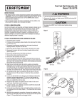
16. With the trolley against the pliers, dispense the remainder of
the belt along the rail assembly toward the opener and around
the sprocket. The sprocket teeth must engage the belt.
17. Check to make sure the belt is not twisted, then connect it to
the flat end of the trolley threaded shaft with the master link
(Figure 4):
• Push pins of master link bar through holes in end of belt and
trolley threaded shaft.
• Push master link cap over pins and past pin notches.
• Slide clip-on spring over cap and onto pin notches until both
pins are securely locked in place.
18. Insert the trolley threaded shaft through the hole in the trolley.
Be sure the belt is not twisted, and the ribbed side faces the
rail.
19. Hold the belt at the trolley shaft as you thread the spring nut by
hand (Figure 5) onto the shaft until finger tight against the
trolley. Do not use any tools.
20. Remove the screwdriver.
21. Set the belt tension:
• Insert a screwdriver tip into one of the nut ring slots and brace
it firmly against the trolley, as shown.
• Place a 7/16" open end wrench on the square end. Rotate the
nut about 1/4 turn until the spring releases and snaps the nut
ring against the trolley (Figure 6).
This sets the spring to optimum belt tension.
22. Replace the belt cap retainer and complete the re-installation
and adjustment of your opener according to your owner’s
manual. NOTE: Before hanging the opener, an additional
hanging bracket is necessary for stability. See Adding An
Additional Hanging Bracket on reverse side.
Figure 5
Spring Nut
Figure 6
Trolley
Square
End
Nut Ring
Figure 7
Nut Ring
BEFORE
1" (2.5 cm)
AFTER RELEASE
1-1/4" (3.18 cm)
23. Replace the old emergency release rope with the new, longer
replacement rope.
24. Reconnect power and operate the door in the UP direction.
25. Increase the UP travel limit by turning the UP limit adjustment
screw in a clockwise direction as shown on label. One turn
equals 2" (5 cm) of travel.
ADDING AN ADDITIONAL HANGING BRACKET:
Cut the enclosed hanging bracket (cross brace) to fit across the
installed hanging brackets. Fasten the cross brace to the top and
bottom hole of the hanging brackets (Figure 7 and Figure 8) using
5/16" -18x7/8" hex bolts, 5/16 lock washers and 5/16" -18 nuts.
Nut Ring
Slot
Square
End
WARNING
To avoid possible SERIOUS INJURY from a falling garage door opener,
fasten it SECURELY to structural supports of the garage. Concrete
anchors MUST be used if installing any brackets into masonry.
CAUTION
Hanging Bracket
(Cross Brace)
Hanging Bracket
(Cross Brace)
Figure 8
Bolt 5/16"-18x7/8"
Lock Washer 5/16"
Nut 5/16"-18
Bolt 5/16"-18x7/8"
Lock Washer 5/16"
Nut 5/16"-18
Lock Washer 5/16"
Nut 5/16"-18
Lock Washer 5/16"
Nut 5/16"-18
REPLACEMENT PARTS
Part No.
Description
183C158-14
41A5250-1
41A3021
4A1008
41B4103
Header Rail Extension
8' (2.4 m) Belt Assembly
Rope
Master Link Kit
Spring Nut Assembly
HARDWARE SHOWN ACTUAL SIZE
Qty
1
1
1
1
1
Hex Bolt
5/16"-18x7/8"
Nut 5/16"-18
Lock Washer 5/16"
Hanging Bracket (Cross Brace) Not shown actual size
114A2748G
©2007, The Chamberlain Group Inc.
All Rights Reserved