1
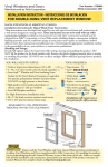
RTM Double Door Installation
Instructions & Maintenance Manual
Instrucciones para la instalación de puertas
dobles RTM y manual de mantenimiento
CALL US FIRST
Do not return to the store!
For assistance with your Retractable Screen installation, or for
additional product information, call our toll-free customer service
number: 1-866-635-4968, or visit us online at www.odl.com.
Important
Be sure to first read through and then follow completely all stepby-step instructions. This will help to insure proper installation
and functionality. Expect installation to take from 2 to 3 hours.
ODL reserves the right to change the product at anytime.
Illustrations may not exactly match your product.
Attention
Retractable Screens are not intended to provide security or
provide for the retention of objects, animals, or persons within
the interior.
PRIMERO LLÁMENOS
¡No devuelva el producto a la tienda!
Si necesita ayuda con la instalación de su malla retractable
o si desea información adicional sobre el producto, llame de
manera gratuita a nuestro servicio al cliente: 1-866-635-4968,
o visite nuestro sitio de Internet en www.odl.com.
Importante
Asegúrese de leer detalladamente y de seguir paso a paso
todas las instrucciones. Esto garantizará una correcta
instalación y funcionalidad. Tiempo estimado de instalación de
2 a 3 horas.
ODL se reserva el derecho de cambiar el producto en cualquier
momento. Es posible que las ilustraciones no concuerden
exactamente con su producto.
Atención
Las mallas retractables no están diseñadas para proporcionar
seguridad ni para retener objetos, animales o personas en el
interior.
Parts Identification For DoubleDoor Hardware Pack
Identificación de las piezas
TOOLS
PARTS
Drill / Taladro
sv"IT
s"ROCADEv
sv"IT
s"ROCADEv
sv"IT
s"ROCADEv
(2) Slide bolt, (2) shim and
(4) 1” pan head phillips screws
for double door
Deslice el perno, la cuña
y los tornillos cabeza
troncocónica de 1" en
estrella para la puerta doble
Hack Saw / Segueta
Measuring Tape /
Cinta para medir
Metal File /
Lima de metal
Pencil / Lápiz
Phillips Screwdriver /
Destornillador de estrella
Square / Escuadra
(1) 3/8” flat head phillips screw (for double door strike plate in Step 11)
Tornillo cabeza plana de 3/8” en estrella para acabado de madera (para la placa
receptora del pestillo de la puerta doble en el paso 12)
NOTE
Please review instruction manual(s) included with your retractable screen(s)
for complete retractable screen parts list.
1
Install Slide Bolts
Instale los pernos deslizantes
TOOLS & PARTS
(2) Slide Bolt Kits /
(2) Juegos de pernos deslizantes
(2) Screen Housings /
(2) Montantes de las mallas
Drill / Taladro
Slide bolts lock one of the screens in place. This screen
goes over the fixed door and acts as the latch point for the
second operable screen.
1
Measure and mark the center point of molding/trim at
the top and bottom.
2
Place slide bolt shim on screen handle surface that
will face inside the house. Mark and drill 1/8” pilot
hole for slide bolt shim on screen handle surface per
directions in illustration #2 (in 1-1/4” from the edge
and flush with the handle’s aluminum edge.)
3
Place slide bolt over shim and, with slide toward
screen fabric, attach using 1” screws.
4
Repeat steps 2 and 3 for opposite/bottom end of handle.
1/8” Drill Bit / Broca de 1/8”
Phillips Screwdriver /
Destornillador Phillips
(4) 1" Pan Head Phillips Screws /
(4) Tornillos de cabeza troncocónica
1”
1
Los pernos deslizantes bloquean una de las mallas en su
lugar. Esta malla cubre la puerta fija y actúa como punto de
enganche para la segunda malla.
1
Mida y marque el punto central del marco de la puerta
en la parte superior e inferior.
2
Coloque la cuña del perno deslizante en la superficie
de la manija de la malla que estará orientada hacia la
casa. Marque y taladre un agujero guía de 1/8” (3,2
mm) para la cuña del perno deslizante en la superficie
de la manija de la malla de acuerdo con la ilustración
Nº 2 (a 1-1/4” [3,2 cm]) del borde y a ras con el borde
de aluminio de la manija).
3
Coloque el perno deslizante sobre la cuña y, con
el resbaladero hacia la malla de tela, fije utilizando
tornillos de 1”.
4
Repita los pasos 2 y 3 para el extremo opuesto/
inferior de la manija.
2
1-1/4" from edge
1-1/4” del borde
3
3
2
Determine Sill Type - For Inswing Doors Only
Determine el tipo de umbral – para puertas con giro hacia adentro únicamente
IMPORTANT
Determine the sill type now since some of the installation
steps will vary. (Single door shown)
Short Sill
Solera corta
1
Short Sill
A short sill stops short of the exterior trim.
Important
See page 5 for short sill preparation. This must be
done prior to installing screen.
1
2
Flush Sill
A flush sill stops flush with the exterior trim.
3
Long/Extended Sill
A long or extended sill extends out past the exterior
trim.
Flush Sill
Solera al ras
2
IMPORTANTE
Determine el tipo de solera ahora ya que algunos de los
pasos de la instalación cambiarán (se muestra una puerta
simple).
1
Solera corta
La solera corta llega justo antes del borde exterior.
Importante
Para la preparación de la solera corta, consulte la
página 5. Esto debe realizarse antes de la instalación
de la malla.
Long/Extended Sill
Solera larga o extendida
2
Solera al ras
La solera al ras llega hasta el ras del borde exterior.
3
Solera larga o extendida
Una solera larga o extendida se extiende más allá del
borde exterior.
3
4
Short Sill Preparation
Preparación de la solera corta
NOTE
If the short sill sits on top of a step, it is required that a
filler board be added for bottom track to rest on.
1
2
1
Filler board not needed when short sills have ground
directly underneath sill.
2
FIller board needed when short sill sits on top of a step.
3
Cut filler board and place under sill lip.
4
Filler must extend out 3/4” beyond the edge of your
exterior trim.
NOTA
Si la solera corta se coloca sobre la parte superior de un
peldaño, es necesario colocar una tira de relleno para
que el riel inferior pueda apoyarse.
3
Exterior
Trim
4
3/4“
Filler
Board
1
No se necesita tabla de ralleno cuando la solera corta
se instala directamente debajo de la placa de umbral.
2
La tabla de relleno es necesaria cuando cuando la solera
corta se coloca en la parte superior de un peldaño.
3
Corte la tabla de relleno y colóquela debajo del
reborde de la solera.
4
El relleno debe sobresalir 3/4” (2,5 cm) del borde
exterior.
Tabla de relleno de ¾” (1,9 cm)
5
3
Install Pull Handles
Instale las manijas
TOOLS & PARTS
1
Align the Pull handle with pre-drilled holes in the
Aluminum Screen Handle. The screw head should
face the interior of your house.
2
Tighten with hand pressure. Over torquing the screw
into the plastic will result in a cracked handle in cold
weather.
1
Alinee la manija plástica con los agujeros pretaladrados
en la manija de aluminio. La cabeza del tornillo debe
estar orientada hacia el interior de la casa.
2
Apriete a mano. Apretar excesivamente los tornillos
en el plástico ocasionará que la manija se raje en
clima frío.
(2) Pull Handle Sets (2 per set) /
(2) Manijar
(2) Screen Housings /
(2) Montantes de las mallas
(4) 1 3/4” Pan Head Screws /
(4) Tornillos de cabeza troncocónica
1-3/4”
Phillips Screwdriver /
Destornillador Phillips
1
2
6
4
Install Screen Housing
Instale el montante de la malla
TOOLS & PARTS
TIP
Have a second person assist in holding the housing to ensure proper alignment.
1
On hinge side of door; align housing to exterior trim.
3/32” Bit / Broca de 3/32”
2
If Short/Flush Sill
Position so housing is level
with bottom of sill face.
(2) Screen Housings /
(2) Montantes de las mallas
Square / Escuadra
4
3ILL
,EVELWITHBOTTOM
OFSILLFACE
If Long/Extended Sill
Position so housing
rests on top of sill.
4RIM
Phillips Drill Bit / Broca Phillips
/2
(OUSING
(OUSING
Drill / Taladro
4RIM
(4) 3” Housing Screws /
(4) Tornillos de 3” para el montante
3ILL
/NTOPOFSILL
3
Housing must be square to sill. Use a square to ensure that this is true.
4
Position so housing has at least 1” of overlap on trim.
Center Point
v/VERLAP
(OUSING
5
4OPVIEWOF
HOUSINGPOSITION
1
IMPORTANT
Be sure screen fabric is properly routed though plastic endcap to avoid
pinching fabric against wall.
5
While maintaining above positions:
s 0REDRILLHOLESUSINGTHEvBIT
s )NSERTvHOUSINGSCREWSINTOTOPANDBOTTOMHOUSINGENDCAPS
Both screws should extend into the exterior trim.
CONSEJO
3
2
5
Center Point
Cuente con la ayuda de otra persona que sostenga el montante para
lograr una alineación adecuada.
1
Del lado de la bisagra de la puerta, alinee el montante con el borde exterior.
2
Si la solera es corta o al ras
Coloque la solera para que el
montante esté nivelado con
la parte inferior del frente de
la solera.
Si la solera es larga o extendida
Coloque la solera para que el
/2 montante se apoye sobre la parte
superior de la solera.
3
El montante debe estar encuadrado con la solera. Utilice la escuadra
para asegurarse de que sea así.
4
Coloque el montante de manera que pase al menos 1” (2,5 cm) del borde.
IMPORTANTE
Cerciórese de que la tela de la malla esté adecuadamente conducida
a través de la tapa terminal de plástico para evitar comprimir el tejido
contra la pared.
5
Con las posiciones arriba mencionadas:
s Perfore con anterioridad los orificios con una broca de 3/32”.
s )NSERTELOSTORNILLOSDEvPARAELMONTANTEENLASTAPASPARALOSEXTREMOSDE
los montantes superior e inferior.
Ambos tornillos deben extenderse hasta el borde exterior.
7
5
Measure and Cut Tracks
Mida y corte los rieles
TIP
TOOLS & PARTS
Make sure measurements are accurate before cutting
tracks.
File / Lima
Hack Saw / Sierra para metales
Pencil / Lápiz
1
Measure the distance from the inside edge of your
screen housing to the to the center point of doorway
you marked in step 1 on page 3.
2
Take step 1 measurement and measure along tracks
to locate the cut line. Mark cut-line with a pencil and
square.
3
Cut tracks along marked cut-line with hack saw. File
any sharp edges smooth if necessary.
Measuring Tape / Cinta métrica
Square / Escuadra
(2) Top Tracks / Riel superior
(2) Bottom Tracks / Riel inferior
CONSEJO
Asegúrese de que las medidas sean correctas antes de
cortar los rieles.
1
2
1
Mida la distancia desde el borde interior del montante
de la malla hasta el punto central de la puerta que
marcó en el paso 1 de la página 3.
2
Tome la medida del paso 1 y mida a lo largo de los
rieles para ubicar la línea de corte. Marque la línea de
corte con un lápiz y una escuadra.
3
Corte los rieles por la línea de corte con una sierra
para metales. Si es necesario, lime los bordes filosos
para que queden suaves.
3
8
6
Drill Holes in Ends of Screen Tracks
Perfore un orificio en el extremo de los rieles de la malla
TOOLS & PARTS
5/32” Bit / Broca de 5/32”
TIP
Lay tracks on a scrap piece of wood. This will make it
easier to drill through both sides of track.
1
Drill / Taladro
Measure 1/4" from both ends of top and bottom
tracks. With pencil make a mark on the small groove.
Measuring Tape / Cinta métrica
If a 3rd screw is needed for support, mark an
additional hole in the middle of the bottom track (not
shown).
Pencil / Lápiz
Square / Escuadra
(2) Top Tracks / Riel superior
2
(2) Bottom Tracks / Riel inferior
TIP
Drill hole at pencil mark using 5/32" drill bit.
Be sure to go through both sides of the tracks.
Remove any burrs from exterior and interior surfaces of
track with metal file.
CONSEJO
Coloque los rieles en un trozo de madera para desechar.
De esta manera le resultará más fácil perforar a través de
ambos lados del riel.
1
Mida ¼” (6,4 mm) desde ambos extremos de los
rieles superior e inferior. Haga una marca con un lápiz
en la ranura pequeña.
Si necesita un 3er tornillo para soporte, marque un
agujero adicional en la mitad del riel inferior (no se
ilustra).
2
2
1
h
3CRAP
7OOD
Perfore un orificio a través de la marca del lápiz utilizando
una broca de 5/32”. Cerciórese de atravesar ambos lados
de los rieles.
CONSEJO
Retire los bordes ásperos de las superficies exteriores
e interiores del riel si fuese necesario con una lima de
metal.
(Botton Track shown in illustration)
(en la ilustración se muestra el riel inferior)
9
7
Measure and Cut Sill Covers
Mida y corte la cubierta de la solera
TOOLS & PARTS
1
Measure the distance between the inside edge of
screen housing to the center of the doorway you
marked in step 1 on page 3.
2
Take measurement from step 1 and measure along
sill covers to locate the cut-line. Mark cut-line with a
pencil and square.
5/32” Bit / Broca de 5/32”
Drill / Taladro
Measuring Tape / Cinta métrica
Pencil / Lápiz
3
Square / Escuadra
(2) Sill Covers / Placa de umbral
Cut sill covers along marked cut-line with hack saw.
File any sharp edge smooth if necessary.
OPTIONAL
Notch sill covers to conform to shape of door trim
if desired.
1
1
Mida la distancia entre el borde interior del montante
de la malla hasta el centro de la puerta que marcó en
el paso 1 de la página 3.
2
Tome la medida del paso 1 y mida a lo largo de los
rieles para ubicar la línea de corte. Marque la línea de
corte con un lápiz y una escuadra.
3
Corte las cubiertas del umbral por la línea de corte
con una segueta. Si es necesario, lime los bordes
filosos para que queden suaves.
Center Point
2
OPCIONAL
Haga una muesca en la placa de cobertura del umbral
para que coincida con la forma del borde de la puerta si
lo desea.
3
10
8
Insert Sill Covers and Install Bottom Tracks
Inserte las tapas de las soleras e instale los rieles inferiores
TIP
Properly aligning bottom track will help ensure screen operates smoothly.
TOOLS & PARTS
(1-3) 1-1/4” Pan Head Screws / (1 a 3)
Tornillos de cabeza troncocónica de 1-1/4”
Drill / Taladro
1
Slide sill covers into bottom track.
2A Thread the handle end cap onto the bead on track.
2B Once threaded, slide track onto housing end cap tab
Phillips Screwdriver /
Destornillador Phillips
and fully seat it.
(2) Sill Covers / (2) Placas de umbral
3
(2) Bottom Tracks / (2) Rieles inferiores
Bottom track must be square to housing. Use a square to ensure that
this is true.
If Short/Flush Sill
Position so bottom track is level and flush (as close as possible) with
top of sill face.
If Long/Extended Sill
Position so bottom track rests on top of sill.
4
1
While maintaining above positions, Insert 1-1/4 pan head screws into
bottom track using pre-drilled hole from step 6 as your guide.
IMPORTANT
Do Not over tighten track screws.
CONSEJO
La alineación correcta del riel inferior garantizará el funcionamiento de la
malla sin problemas.
1
2A
Screen
Housing
Tab
2B
Deslice las cubiertas del umbral en el riel inferior.
2A Inserte la pestaña en el reborde del riel.
2B
Una vez insertado, deslice el riel en la pestaña del montante y
asiéntelo completamente.
3
El riel inferior deberá quedar a escuadra con el montante. Utilice una
escuadra para comprobarlo.
Handle
End Cap
Si el umbral es corto o al ras
Coloque de forma tal que el riel inferior se encuentre a nivel y a
ras (tan cerca como sea posible) con la parte superior del frente del
umbral.
Si el umbral es largo o prolongado
Coloque de forma que el riel inferior se apoye sobre el umbral.
3
4
Mientras conserva las posiciones superiores, inserte el tornillo cabeza
troncocónica de 1-1/4 en el riel inferior utilizando el agujero pretaladrado
del paso 6 como guía.
IMPORTANTE
4
No ajuste demasiado los tornillos.
11
9
Install Sill Cover Screws
Instale los tornillos de la cubierta de la solera
TOOLS & PARTS
(12) 3/4” Flat Head Screws /
(12) Tornillos de cabeza plana de 3/4”
3/32” Bit / Broca de 3/32”
Drill / Taladro
Phillips Screwdriver /
Destornillador Phillips
(2) Sill Covers / Placa de umbral
TIP
Do not over tighten sill cover screws. It could cause
binding of the screen.
1
Center sill covers on sill.
2
Pre-drill holes in sill using the 3/32” bit. Use pre-punched
holes in sill cover as locater for drilling.
3
Insert 3/4" flat head screws using phillips screwdriver.
NOTE
If the sill covers were cut in a previous step, all 12 screws might not
be required.
CONSEJO
No apriete demasiado los tornillos de la cubierta de umbral
pues ello podría ocasionar que se atasque la malla.
1
1
Centre la cubierta del umbral en el umbral.
2
Pretaladre agujeros en el umbral utilizando la broca de 3/32”.
Utilice los agujeros preperforados en la cubierta del umbral como
localizador para taladrar.
3
Instale utilizando tornillos cabeza plana de ¾” y un destornillador.
NOTA
2
Si cortó la cubierta del umbral en un paso anterior, es posible que no
necesite los 6 tornillos.
3
12
10
Install Top Tracks
Instale los rieles superiores
TOOLS & PARTS
(4) 1-1/4” Pan Head Screws /
(4) Tornillos de cabeza troncocónica
1-1/4”
Drill / Taladro
Phillips Screwdriver /
Destornillador Phillips
TIP
Do not over tighten track screws. It could cause binding of the screen.
1A
Thread the handle end cap onto the bead on track.
1B
Once threaded, slide track onto housing end cap tab and fully seat it.
2
(2) Top Tracks / (2) Rieles superiores
3
Insert 1-1/4" pan head screw through tab end of top track and into exterior trim
of home. Use the pre-drilled hole from step 6 as your guide.
Locating top track position
s 0ULLSCREENHANdle towards center point of track and hold. This will align
the top track with the bottom track and locate top track position.
Tab
Handle
End Cap
1B
s -AKESURETOPTRACKREMAINSFULLYSEATEDTO the end cap tab as in step 1B.
4
Insert 1-1/4" pan head screw into top track.
Do not use square. Use the pre-drilled hole from step 6 as your guide.
NOTES
Open and close screen several times to ensure proper track installation.
Be sure to avoid binding of pull handle. Be sure the dust seal in both tracks
cover the top and bottom edge of screen
1A
5
Repeat for second/opposite side screen.
CONSEJO
No ajuste demasiado los tornillos del riel. La malla podría quedar fija.
2
4
1A Inserte la pestaña en el reborde del riel.
1B Una vez insertado, deslice el riel en la pestaña del montante y
asiéntelo completamente.
2
3
3
4
Inserte un tornillo de cabeza troncocónica de 1-1/4” a través de la
pestaña terminal del riel superior y en el borde exterior de la casa.
Utilice el agujero pretaladrado del paso 6 como guía
Ubicación de la posición del riel superior
s (ALELAMANIJADELAMALLAHACIAELPUNTOCENTRALDELRIELY
sosténgala. Esto alineará el riel superior con el inferior y ubicará
la posición del riel superior.
s #ERCIØRESEDEQUEELRIELSUPERIORPERMANEZCACOMPLETAMENTE
asentado en la pestaña del montante como en el paso 1B.
Inserte el tornillo cabeza troncocónica de 1-1/4” en el riel superior.
No utilice la escuadra Utilice el agujero pretaladrado del paso 6
como guía.
NOTA
Abra y cierre la malla varias veces para asegurarse de que los rieles
están instalados correctamente.
5
Repita para la segunda persiana/la del lado opuesto.
13
11
Double Door Magnetic Catch & Slide Bolt Holes
Pestillo magnético de la puerta doble y orificios de los pernos deslizantes
TOOLS & PARTS
1
(1) 3/8” Flat Head Screw /
(1) Tornillos de cabeza plana de 3/8”
Remove the 5/8" screw and cover from one of the magnetic
catches and remove magnet. Then replace cover and screw.
2
(4) 1” Painted Flat Head Screws /
(4) Tornillos de cabeza plana de 1”
pintados
Attach strike plate to this catch with 2 notches facing out. If
you determine that you need more magnetic force, simply flip
the plate over. Use 3/8" screw.
TIP
For attaching the strike plate (step 2), you may want to
drill pilot holes (5/64" or 1/16") before inserting the 3/8"
screws.
Phillips Screwdriver /
Destornillador Phillips
Drill / Taladro
7/32” Bit / Broca de 7/32”
1
Retire el tornillo de 5/8” y la tapa de uno de los pestillos
magnéticos y retire el imán. Luego vuelva a colocar la tapa y
el tornillo.
2
Fije la placa a este pestillo con las dos muescas orientadas
hacia afuera. Si considera que necesita más fuerza magnética,
simplemente déle vuelta a la placa. Utilice tornillos de 3/8”.
5/64" or 1/16" Bit (Optional) /
Broca de 5/64” o 1/16" (opcional)
(2) Magnetic Catches /
(2) Pestillos magnéticos
Strike Plate /
Placa receptora de pestillo
CONSEJO
Retire los bordes ásperos de las superficies exteriores
e interiores del riel si fuese necesario con una lima de
metal.
1
Cover
1
3/8"
Screw
1
5/8"
Screw
2
Remove
Magnet
14
11
Double Door Magnetic Catch & Slide Bolt Holes (Continued)
Pestillo magnético de la puerta doble y orificios de los pernos deslizantes
TOOLS & PARTS
(1) 3/8” Flat Head Screw /
(1) Tornillos de cabeza plana de 3/8”
(4) 1” Painted Flat Head Screws /
(4) Tornillos de cabeza plana de 1”
pintados
3
On inside of both screen handles, attach catches facing each
other using four 1” painted flat head screws. Insert into
predrilled holes in screen handles.
4
Pull screen over fixed side all the way to the center mark.
Mark hole locations for slide bolt pins at top and bottom. Drill
7/32” hole in trim at top and in sill at bottom. If pin does not
reach top trim, install filler block and drill 7/32” hole in block.
Slide pins into holes to fix the screen in place.
Phillips Screwdriver /
Destornillador Phillips
Slide the primary screen until latches make contact to be sure
they align properly.
Drill / Taladro
7/32” Bit / Broca de 7/32”
CONGRATULATIONS
Your installation is now complete.
5/64" or 1/16" Bit (Optional) /
Broca de 5/64” o 1/16" (opcional)
Refer to page 16 for “operation and maintenance”
tips.
(2) Magnetic Catches /
(2) Pestillos magnéticos
Strike Plate /
Placa receptora de pestillo
3
3
En la parte interior de ambas manijas de la malla, fije los pestillos
enfrentados utilizando tornillos cabeza plana de 1” pintados.
Inserte en los agujeros pretaladrados de las manijas de la malla.
4
Extienda la malla sobre la puerta fija hasta la marca central del
borde. Marque las ubicaciones de los agujeros para los pernos
pasadores deslizantes en la parte superior e inferior. Taladre
un orificio de 7/32” (4 mm) en el borde en la parte superior y
en el umbral en la parte inferior. Si el pasador no llega al borde
superior, coloque un bloque de relleno y taladre un agujero
de 7/32” (4 mm) en el bloque. Deslice los pasadores en los
agujeros.
Deslice la malla principal hasta que los pestillos hagan contacto
para lograr que queden alineados y agarren de manera
adecuada.
FELICITACIONES
Su instalación ahora está terminada.
Consulte la página 16 para los consejos de
“Funcionamiento y mantenimiento”.
4
Drill For Slide Bolts
Top & Bottom
15
Operation and Maintenance
Funcionamiento y mantenimiento
Loosen Tight Screws
Afloje los tornillos apretados
Lubricate
Lubrique
Operation – Binding
If screen binds during retraction, try the following:
s 4RACKSCREWSCOULDBETOOTIGHT4RYLOOSENINGASLIGHTLY
s !DDALUBRICANTSUCHASSILICONSPRAY
s -AKESURETOPTRACKISINSTALLEDPERSTEP
Maintenance
s #HECKFORLOOSESCREWS
s #LEANOUTTRACKSWITHAVACUUM
s ,IGHTLYLUBRICATETRACKSWITHSILICONSPRAY
s &ULLYRETRACTSCREENSDURINGFREEZING
Magnetic Force
If you require more magnetic attractive force, Reverse your strike
plate so that flat side faces magnets.
Clean with Vacuum
Limpie con aspiradora
Retract Screen During Freezing
Repliegue la malla durante las heladas
Adjust Magnetic Force
Ajuste la fuerza magnética
Caution
s $ONOTDRAGORROLLHEAVYOBJECTSOVERTRACKS
s $ONOTAPPLYEXCESSIVEPRESSURETOTHESCREENHANDLE)FSCREEN
binds, check for obstructions or misaligned tracks.
For assistance with retractable screen installation or for
additional product information, call ODL customer service
toll free at 1.866.635.4968.
Funcionamiento – Fijación
Si la malla queda fija durante la retracción, intente lo siguiente:
s ,OSTORNILLOSDELRIELPUEDENESTARDEMASIADOAPRETADOS4RATEDE
aflojarlos ligeramente.
s !×ADAUNLUBRICANTECOMOUNSPRAYDESILICONA
s #ERCIØRESEDEQUEELRIELSUPERIORESTÏINSTALADODEACUERDOCONEL
paso 10.
Mantenimiento
s 6ERIlQUESIHAYTORNILLOSmOJOS
s ,IMPIELOSRIELESCONUNAASPIRADORA
s ,UBRIQUELIGERAMENTELOSRIELESCONUNSPRAYDESILICONA
s 2EPLIEGUELASMALLASCOMPLETAMENTEDURANTELASTEMPERATURASDE
congelación.
Fuerza magnética
Si necesita más fuerza magnética, invierta la placa receptora del
pestillo de modo que el lado plano esté orientado hacia los imanes.
Precaución
s .OARRASTRENIRUEDEOBJETOSPESADOSSOBRELOSRIELES
s .OPRESIONEDEMASIADOLAMANIJADELAMALLA3ILAMALLASE
atasca, revise si hay obstrucciones o rieles mal alineados.
Si necesita ayuda para la instalación de su malla retráctil o si
desea información adicional sobre el producto, llame gratis al
servicio al cliente de ODL al 1.866.635.4968.
16
Limited Warranty for ODL Retractable Screen
Effective 02/04
Warranty Coverage
a. An adequate description of the claimed defect(s); b. The
date of the Consumer’s purchase, the place of purchase,
and the purchase price.
Subject to the conditions, exclusions and limitations herein,
ODL Incorporated (“ODL”) warrants that its Retractable
Screen Product (“Product”) is free from defects in material and
workmanship that would render the Product unfit for its normal
and recommended use.
3. The Consumer must, if requested by ODL, permit ODL
or its representative to inspect the Product.
Remedies
THIS WARRANTY APPLIES AND EXTENDS ONLY TO THE
ORIGINAL CONSUMER PURCHASING THIS PRODUCT.
THE DURATION OF THIS WARRANTY BEGINS ON THE
DATE OF PURCHASE BY THE CONSUMER AND EXTENDS
FOR A PERIOD OF FIVE YEARS.
!FTERRECEIVINGAVALIDCLAIM/$,WILLAT/$,SOPTIONEITHER
(a) repair the Product or provide a replacement Product of like
KINDANDDESIGNORBUPONTHERETURNOFTHE0RODUCTTO/$,
refund the Consumer the purchase price of the Product paid
by the Consumer.
Exclusions from Coverage
This warranty does not cover:
s$AMAGETOTHESCREENMESHCOMPONENTOFTHEPRODUCT
s!0RODUCTTHATISNOTINSTALLEDONASTEELWOODORlBERGLASS
entry door.
s$EFECTSORDAMAGESRESULTINGINFAILURETOINSTALLOROPERATE
the Product in accordance with ODL’s installation instructions.
s$EFECTSORDAMAGESRESULTINGFROMMODIlCATIONSOR
attachments to the Product.
s$AMAGETOTHEENTRYDOOR
s$EFECTSORDAMAGESARISINGOUTOFIMPROPERHANDLING
CLEANINGMAINTENANCEOPERATIONDEFECTIVEORIMPROPER
INSTALLATIONINCLUDINGINSTALLATIONNOTINACCORDANCEWITH
ODL’s installation
INSTRUCTIONSIMPROPERSTORAGENORMALWEARANDTEAR
accident, act of God, intentional human acts, misuse,
abuses, or any circumstances beyond the control of ODL.
s$EFECTSORDAMAGESRESULTINGFROMSHIPMENTBYCOMMON
carriers, private transportation or other means of
transportation.
If ODL elects to provide a replacement Product, the limited
warranty for the replacement product will last for the balance
OFTHEWARRANTYOFTHEORIGINAL0RODUCT
ODL’S LIABILITY UNDER THIS WARRANTY IS LIMITED TO
EITHER (A) OR (B) ABOVE, AND ODL WILL IN NO EVENT
BE RESPONSIBLE FOR SHIPPING, LABOR, REMOVAL OF
ORIGINAL PRODUCT, INSTALLATION OF REPLACEMENT
PRODUCT, FINISHING EXPENSES, OR OTHER CHARGES,
COSTS OR CLAIMS INCURRED BY THE CONSUMER.
Disclaimer of Warranty
NO IMPLIED WARRANTY, INCLUDING WARRANTY OF
MERCHANTABILITY OR OF FITNESS FOR A PARTICULAR
PURPOSE, SHALL APPLY TO THE PRODUCT (OR ANY
REPLACEMENT) BEYOND THE DURATION OF THIS
WRITTEN WARRANTY. (Some states do not allow limitations
ONHOWLONGANIMPLIEDWARRANTYLASTSSOTHEABOVELIMITATION
may not apply to you.)
Inspection and Discovery of Defect
Limitation of Remedies
It is the Consumer’s responsibility to inspect the Product
immediately upon receipt of the Product. If a defect covered
under this warranty is discovered upon inspection, the
customer must follow the Warranty Claim Procedure set forth
below.
THE REMEDIES SET FORTH ABOVE ARE THE
CONSUMER’S EXCLUSIVE REMEDIES FOR BREACH
OF WARRANTY OR NEGLIGENCE. IN NO CASE SHALL
ODL BE LIABLE TO THE CONSUMER OR ANY OTHER
PERSON FOR ANY GENERAL, SPECIAL, INCIDENTAL OR
CONSEQUENTIAL DAMAGES. (Some states do not allow the
EXCLUSIONORLIMITATIONOFINCIDENTALORCONSEQUENTIALDAMAGES
so the above limitations or exclusions may not apply to you.)
/$,SHALLHAVENOOBLIGATIONUNDERTHISWARRANTYWITHRESPECT
to any defect reasonably discoverable upon immediate
inspection once the product has been installed.
If a defect occurs after installation within the warranty period,
then the consumer must follow the Warranty Claim Procedure
set forth below.
5NLESSMODIlEDINALATERWRITINGSIGNEDBYBOTH/$,AND
Consumer, this warranty is the complete and exclusive
warranty related to the Product, and it supersedes all earlier
AGREEMENTSANDOTHERCOMMUNICATIONSRELATINGTOTHE0RODUCT
No employee of ODL or any other party is authorized to make
any warranty in addition to this warranty. Invalidation of any
one or more of the other provisions of this warranty shall not
invalidate or affect one of the other provisions. This warranty is
not transferable.
Warranty Claim Procedure
4HE#ONSUMERMUSTFOLLOWTHEFOLLOWINGPROCEDURETOMAKEA
claim under this warranty:
1. The Consumer must present a written claim to ODL within
DAYSAFTERDISCOVERINGTHEDEFECT4HE#ONSUMERMUST
SUBMITITSCLAIMTOTHEFOLLOWINGADDRESS/$,)NCORPORATED
Customer Service, 215 East Roosevelt Avenue, Zeeland,
-ICHIGAN/$,MUSTRECEIVETHISWRITTENCLAIMWITHIN
the warranty period.
4HISWARRANTYGIVESTHE#ONSUMERSPECIlCLEGALRIGHTSAND
THE#ONSUMERMAYALSOHAVEOTHERLEGALRIGHTSWHICHMAY
vary from state to state.
4HE#ONSUMERMUSTUSEREASONABLEDILIGENCETOINCLUDE
ALLOFTHEFOLLOWINGINTHEWRITTENCLAIM
17
Garantía limitada para la malla retráctil ODL
6IGENTEDESDE
Cobertura de la garantía
%LCONSUMIDORDEBERÈPROCURARINCLUIRDILIGENTEMENTEENEL
RECLAMOPORESCRITOLASIGUIENTEINFORMACIØN
/$,)NCORPORATEDh/$,vGARANTIZAQUESUPRODUCTODE
malla retráctil (“Producto”) no presenta defectos de material
ni de mano de obra que ocasionen que el Producto sea
inadecuado para su uso normal o para el uso recomendado.
%STAGARANTÓAESTÈSUJETAALASCONDICIONESEXCLUSIONESY
limitaciones especificadas en el presente documento.
A5NADESCRIPCIØNADECUADADELLOSDEFECTOSB,AFECHA
DECOMPRAPORPARTEDELCONSUMIDORELLUGARYELPRECIODELA
compra.
%LCONSUMIDORDEBERÈSI/$,OSUREPRESENTANTEASÓLO
SOLICITAREPERMITIRLAINSPECCIØNDELPRODUCTO
ESTA GARANTÍA DE POR VIDA SE APLICA Y EXTIENDE
ÚNICAMENTE AL CONSUMIDOR ORIGINAL QUE COMPRE
ESTE PRODUCTO. LA DURACIÓN DE ESTA GARANTÍA
COMIENZA EN LA FECHA EN QUE EL CONSUMIDOR
ADQUIERE EL PRODUCTO Y SE EXTIENDE POR UN
PERÍODO DE CINCO AÑOS.
Recursos
$ESPUÏSDERECIBIRUNRECLAMOVÈLIDO/$,ASUENTERA
DISCRECIØNAREPARARÈELPRODUCTOOLOREEMPLAZARÈPOR
UNODETIPOYDISE×OSIMILAROBLUEGODELADEVOLUCIØNDEL
producto a ODL, se le reembolsará al consumidor el precio
QUEPAGØPORELPRODUCTO3I/$,ELIGEPROPORCIONARUN
0RODUCTODEREEMPLAZOLAGARANTÓALIMITADADELREEMPLAZO
DURARÈSØLOELRESTODELPERÓODODEGARANTÓAORIGINALDEL
Producto.
Exclusiones de la cobertura
%STAGARANTÓANOAMPARA
s$A×OSALCOMPONENTEDELAMALLADEESTEPRODUCTO
s5NPRODUCTOQUENOESTÏINSTALADOENUNAPUERTADE
entrada de acero, madera o fibra de vidrio.
s$EFECTOSODA×OSQUERESULTENCOMOCONSECUENCIADENO
SEGUIRLASINSTRUCCIONESDEINSTALACIØNDE/$,PARAINSTALAR
o utilizar el producto.
s$EFECTOSODA×OSQUERESULTENCOMOCONSECUENCIADE
hacer modificaciones o colocar anexos en el producto.
s$A×OSALAPUERTADEENTRADA
s,OSDEFECTOSODA×OSQUESURJANDELMANEJOINADECUADO
OLIMPIEZAMANTENIMIENTOFUNCIONAMIENTOINSTALACIØN
DEFECTUOSAOINADECUADAINCLUYENDOLAINSTALACIØNQUE
NOESTÏDEACUERDOCONLASINSTRUCCIONESDEINSTALACIØN
DE/$,ALMACENAJEINADECUADODESGASTENORMALY
DESGARROACCIDENTECATÈSTROFESNATURALESACTOSHUMANOS
intencionales, uso inadecuado, abuso, o cualquier otra
circunstancia que se encuentre más allá del control de
ODL.
s,OSDEFECTOSODA×OSQUEPUEDANOCASIONARSEDURANTEEL
ENVÓOPORMEDIODETRANSPORTECOMÞNTRANSPORTEPRIVADOU
otros medios de transporte.
LA RESPONSABILIDAD DE ODL BAJO ESTA GARANTÍA
ESTÁ LIMITADA A LOS PUNTOS (A) Y (B) INDICADOS
ANTERIORMENTE, Y EN NINGÚN CASO ODL SERÁ
RESPONSABLE POR EL ENVÍO, MANO DE OBRA,
REMOCIÓN DEL PRODUCTO ORIGINAL, INSTALACIÓN
DEL PRODUCTO DE REEMPLAZO, GASTOS DE ACABADO
NI NINGÚN OTRO CARGO, COSTO O RECLAMO EN QUE
INCURRA EL CONSUMIDOR.
Exención de responsabilidad de la garantía
NINGUNA GARANTÍA IMPLÍCITA, INCLUYENDO LA
GARANTÍA DE COMERCIABILIDAD O DE ADECUACIÓN
PARA UN FIN EN PARTICULAR, SERÁ APLICABLE AL
PRODUCTO (O A CUALQUIER REEMPLAZO) MÁS ALLÁ
$%,!$52!#)».$%%34!'!2!.4¶!%3#2)4!!LGUNOS
ESTADOSNOPERMITENLIMITACIONESENCUANTOALADURACIØN
DEUNAGARANTÓAIMPLÓCITAPORLOQUELALIMITACIØNINDICADA
anteriormente puede que no aplique en su caso)
Inspección y hallazgo de un defecto
Limitación de los recursos
Es responsabilidad del consumidor inspeccionar el producto
INMEDIATAMENTEDESPUÏSDEHABERLORECIBIDO3IDESPUÏSDE
LAINSPECCIØNSEDESCUBREUNDEFECTOAMPARADOBAJOESTA
GARANTÓAELCONSUMIDORDEBESEGUIRELPROCEDIMIENTOPARA
RECLAMOENGARANTÓAQUESEESTABLECEACONTINUACIØN
LOS RECURSOS INDICADOS ANTERIORMENTE SON
LOS RECURSOS EXCLUSIVOS DEL CONSUMIDOR PARA
EL INCUMPLIMIENTO DE LA GARANTÍA O NEGLIGENCIA.
EN NINGÚN CASO ODL SERÁ RESPONSABLE ANTE EL
CONSUMIDOR NI ANTE CUALQUIER OTRA PERSONA POR
DAÑOS GENERALES, ESPECIALES, ACCIDENTALES O
2%35,4!.4%3!LGUNOSESTADOSNOPERMITENLAEXCLUSIØNO
LIMITACIØNDEDA×OSACCIDENTALESORESULTANTESPORLOTANTOLAS
limitaciones o exclusiones anteriormente indicadas puede que
no apliquen en su caso).
$EACUERDOAESTAGARANTÓA/$,NOTENDRÈOBLIGACIØNALGUNA
con respecto a cualquier defecto que se pueda descubrir
LUEGODEUNAINSPECCIØNRAZONABLEINMEDIATAUNAVEZQUEEL
producto haya sido instalado.
%STAGARANTÓAESLAGARANTÓACOMPLETAYEXCLUSIVARELACIONADA
con el Producto a menos que sea modificada posteriormente
por escrito y firmada tanto por ODL como por el Consumidor y
LAMISMASUSTITUYETODOSLOSACUERDOSANTERIORESASÓCOMOOTRAS
comunicaciones relacionadas con el Productov.
3IOCURRIEREUNDEFECTODESPUÏSDELAINSTALACIØNDENTRO
DELPERÓODODEGARANTÓAELCONSUMIDORDEBERÈSEGUIREL
PROCEDIMIENTODERECLAMODELAGARANTÓAQUESEESTABLECEA
CONTINUACIØN
Procedimiento de reclamo de la garantía
%STAGARANTÓALEBRINDAALCONSUMIDORDERECHOSLEGALES
ESPECÓlCOSYELCONSUMIDORPUEDETENEROTROSDERECHOSLEGALES
QUEPUEDENVARIARSEGÞNELESTADO
%LCONSUMIDORDEBERÈSEGUIRELSIGUIENTEPROCEDIMIENTOPARA
HACERUNRECLAMOBAJOESTAGARANTÓA
1. El consumidor deberá presentar un reclamo por escrito
A/$,DENTRODELOSDÓASSIGUIENTESALDESCUBRIMIENTO
del defecto. El consumidor deberá presentar su reclamo a la
SIGUIENTEDIRECCIØN/$,)NCORPORATED#USTOMER3ERVICE
%AST2OOSEVELT!VENUE:EELAND-ICHIGAN/$,
DEBERÈRECIBIRESTERECLAMOPORESCRITODENTRODELPERÓODODE
GARANTÓA
18
19
1.866.635.4968
© 2007 ODL Inc.
16593-023 (Rev. 8/09)