1
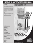
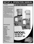
Dust hood rotates 360°.
Support arm extends up to 12”.
Wide dust hood captures chips, dust and
debris.
Powerful 1 HP motor features sealed bearings and shaft for quiet, long-lasting operation.
Comfort grip carrying handle for easy
portability to place the unit where you
need it.
Flexible 4” x 6’ (1.8 m) collection hose
included.
Adjustable multi-position steel support
arm to accommodate a variety of
different machines or applications.
INLET DIAMETER
4” (102 mm)
AIRFLOW CAPACITY
700 CFM
HOSE LENGTH
4” (102 mm) X 6’ (1.8 m)
DUST HOOD
10” (254 mm) x 4” (102 mm)
SOUND RATING
78 dB
STATIC PRESSURE
4.3 INCHES OF WATER
BAG CAPACITY
15 GAL (655 L)
OVERALL DIMENSIONS (L x W x H)
44 1⁄2” x 18 7⁄8” x 43 1⁄4”
(1130 x 480 x 1100 mm)
MOTOR
1 HP, 110 V, 7 A
WEIGHT
51.7 LBS (23.5 Kg)
FILTRATION CAPACITY
30 MICRONS
REVISION 3 JUN 22/06
GENERAL® INTERNATIONAL
8360 Champ-d’Eau, Montreal (Quebec) Canada H1P 1Y3
Telephone (514) 326-1161 • Fax (514) 326-5555 • www.general.ca
THANK YOU
for choosing this General International model 10-050 Dust collector.
This dust collector has been carefully tested and inspected before shipment and if properly
used and maintained, will provide you with years of reliable service. To ensure optimum performance and trouble-free operation, and to get the most from your investment, please take
the time to read this manual before assembling, installing and operating the unit.
The manual’s purpose is to familiarize you with the safe operation, basic function, and features
of this dust collector as well as the set-up, maintenance and identification of its parts and components. This manual is not intended as a substitute for formal woodworking instruction, nor to
offer the user instruction in the craft of woodworking. If you are not sure about the safety of
performing a certain operation or procedure, do not proceed until you can confirm, from
knowledgeable and qualified sources, that it is safe to do so.
Once you’ve read through these instructions, keep this manual handy for future reference.
GENERAL ® INTERNATIONAL WARRANTY
All component parts of General® International machinery are carefully tested and inspected during all stages of
production, and each machine is thoroughly inspected upon completion of assembly. Because of our commitment to quality and customer satisfaction, General® International agrees to repair or replace, within a period of 24
months from date of purchase, any genuine part or parts which, upon examination, prove to be defective in workmanship or material. In order to obtain this warranty, all defective parts must be returned freight pre-paid to
General® International Mfg. Co., Ltd. Repairs attempted without our written authorization will void this warranty.
Disclaimer: The information and specifications in this manual pertain to
the unit as it was supplied from the factory at the time of printing.
Because we are committed to making constant improvements, General
International reserves the right to make changes to components, parts
or features of this unit as deemed necessary, without prior notice and
without obligation to install any such changes on previously delivered
units. Reasonable care is taken at the factory to ensure that the specifications and information in this manual corresponds with that of the unit
with which it was supplied. However, special orders and “after factory”
modifications may render some or all information in this manual
inapplicable to your machine. Further, as several generations of this
model of dust collector and several versions of this manual may be in
circulation, if you own an earlier or later version of this unit, this manual
may not depict your machine exactly. If you have any doubts or questions contact your retailer or our support line with the model and serial
number of your unit for clarification.
Rules for Safe Operation
To help ensure safe operation, please take a moment to learn the machine’s applications and limitations, as well as potential hazards. General® International disclaims any real or implied warranty and
holds itself harmless for any injury that may result from improper use of its equipment.
1. Do not operate machinery when tired, distracted or
under the effects of drugs, alcohol or any medication
that impairs reflexes or alertness.
2. Do not operate this unit until a hose is installed onto
the dust inlet.
3. The working area should be well lit, clean and free of
debris.
4. Keep children and visitors at a safe distance; do not
permit them to operate the unit.
5. Childproof and tamper proof your shop and all machinery with locks, master electrical switches and
switch keys, to prevent unauthorized or unsupervised
use.
6. Stay Alert! Give our work your undivided attention.
Even a momentary distraction can lead to serious
injury.
11. Do not handle the electric plug with wet hands.
12. Do not vacuum anything that is burning, smoking or
smoldering, such as cigarettes, matches or hot ashes.
13. To avoid potential health hazards from vapors or
dusts, do not vacuum toxic material.
14. Do not use this unit outdoors or on or near wet surfaces.
15. Make sure the unit is properly grounded. If tool is equipped with three-prong plug, it should be plugged
into a three-pole receptacle. Never remove the third
prong.
16. Always disconnect tool from power before servicing,
performing any maintenance or repairs and when
changing bags or hoses, or if the machine will be left
unattended.
17. Do not put any foreign objects into the ventilation inlet
or outlet openings.
7. Fine particulate saw dust is a carcinogen that can be
hazardous to health. Work in a well ventilated area
and wear eye, ear and respiratory protection devices.
18. Make sure the switch is in "OFF" position before plugging in cord.
8. Do not wear loose clothing, gloves, bracelets, necklaces, or ornaments while operating machinery.
19. Never stand on machinery. Serious injury could result
if the unit is tipped over.
9. Do not vacuum or use this Dust Collector near flammable or combustible liquids, gases, gasoline or other
fuels, lighter fluid, cleaners, oil or solvent-based paints,
natural gas, hydrogen, explosive dust, grain dust, magnesium dust, or gun powder.
20. The use of parts and accessories NOT recommended
by General International may result in equipment malfunction or risk injury.
10. Never leave the machine running with the power when
not in operation.
DO NOT OPERATE THIS UNIT UNTIL THE PVC HOSE IS INSTALLED ONTO THE DUST INLET PORT.
IMPORTANT NOTICE
HANDLING THE MACHINE
The total weight of the machine is 52 LBS. Do not pull or carry the machine by any part other than it’s handle.
Sound Level
The sound level of this machine is rated at approximately 85 dB during operation. Make sure that adequate
hearing protection is used and that the overall sound level within the working environment is taken into
consideration.
PORTABLE DUST COLLECTOR
10-050
UNPACKING AND CHECKING CONTENTS
UNPACK AND REMOVE ALL COMPONENTS OF YOUR MACHINE FROM THE BOX AND COMPARE WITH THE PARTS LISTED
BELOW. REPORT DAMAGED OR MISSING ITEMS TO YOUR DEALER/DISTRIBUTOR IMMEDIATELY:
DUST COLLECTOR W/BASE & HANDLE
DUST HOOD UPPER SUPPORT ARM
DUST HOSE
DUST HOOD
“L” BRACKET
LOCK KNOB (3)
HOSE CLAMP (2)
BAG CLAMP
CASTER (4)
SHORT CARRIAGE BOLT
3
COLLECTION / FILTER BAG
SCREW LOCK KNOB
FASTENING BRACKET
DUST HOOD LOWER SUPPORT ARM
LONG CARRIAGE BOLT
FLANGE BOLT (2)
FLAT WASHER
KEY / WRENCH
ADHESIVE FOAM GASKET
SPROCKET WASHER (2)
A S S E M B LY
STEP 1 - INSTALLING THE CASTERS ON THE BASE FRAME.
STEP 2 – MOUNTING THE LOWER SUPPORT ARM.
Lay the dust collector on its side as shown and using
the supplied wrench, , install the 4 casters, , to the
underside of the base frame, . Tighten the caster
bolts into the corresponding holes in the base frame
until snug.
Using the 2 supplied flange bolts, , loosely attach
the fastening bracket, , to the dust collector. Fit the
lower support arm, , into the opening between the
dust collector and the mounting bracket as shown.
For a secure stable fit, slide the end of the support
arm down through the opening so that protrudes
roughly 1/2” below the bottom of the mounting
bracket. Then, tighten the flange bolts to clamp the
support arm securely against the dust collector.
Attach the screw lock knob,
, to the support
arm, , as shown. This knob is used to secure the arm
at the desired.
STEP 3 – INSTALLING THE DUST HOOD UPPER SUPPORT ARM
Using the long carriage bolt, , flat washer, , and
one lock knob, ,attach the dust hood upper support arm, , to the lower arm, , as shown. The lock
knob is used to secure the upper arm in the desired
position or angle.
4
STEP 4 - MOUNTING THE DUST HOOD
Using the short carriage bolt, , and one lock knob, , attach the “L” bracket, ,and sprocket washer, , to the end
of the upper support arm, . The lock knob is used to secure the dust hood (once installed on the “L” bracket) at
the desired angle.
Using the remaining lock knob, , fit the dust hood, , onto the “L” bracket
knob is used to secure the dust hood to the desired pivot position.
STEP 5 – ATTACHING THE DUST HOSE & COLLECTION/FILTER BAG
Install a hose clamp, , on each end of the dust
hose, . Slip one end of the hose onto the dust hood,
, and using a Phillips head screw driver (not supplied)
tighten the hose clamp until it is secure on the dust
hood.
Slip the opposite end of the dust hose onto the dust
collector inlet and tighten the clamp until it is securely in
place.
and sprocket washer,
To create an airtight seal between the dust bag and the
air outlet, peal off the backing of the adhesive foam
gasket, , and stick the gasket onto the dust collector
outlet - cutting it to length, if needed.
Fit the bag, , over the outlet and secure the bag onto
the outlet using the supplied bag clamp, . Positioning
and tightening the clamp on the gasket will ensure an
airtight seal.
YOUR DUST COLLECTOR IS NOW READY TO BE PUT INTO SERVICE.
5
. The lock
CONNECTING TO A POWER SOURCE
Plug the dust collector into a proper receptacle. Your power tools should be connected to a dedicated electrical circuit of not less than #14 wire and should be
protected with a 15 amp time lag fuse. If an extension cord is needed, use only
3-wire cords with 3-prong grounded-type plugs and 3-pole receptacles.
Grounding: This tool must be grounded to protect the operator from electrical shock. The
supplied motor recommended for your dust collector is wired for 110 Volt, single phase, and
has a 3-conductor cord and 3-prong grounded plug to fit a grounded-type receptacle,
. Do not remove the 3rd prong (grounding pin) from the plug to make it fit into an old
2-hole wall socket. If an adapter plug is used, , it must be attached to the metal screw of the receptacle.
Note: Use of an adaptor plug is illegal in some areas. Check your local codes.
Before connecting the motor to the power line, make sure that the switch is in the OFF position and that the
electrical current is of the same type as that stamped on the motor nameplate. All electrical connections
should have proper contact. Running on low voltage will damage the motor.
To avoid risk of shock or fire, do not operate with a damaged power cord or plug.
Replace damaged cord or plug immediately.
ADJUSTMENTS AND CONTROLS
POWER “ON”/”OFF”
Make sure the switch is in the “OFF” position before plugging the power cord into a matching outlet.
POWER ON
POWER OFF
SAFETY KEY
(PREVENTS START-UP WHEN REMOVED)
6
7
PARTS LIST
10-050
PART N0.
DESCRIPTION
SPECIFICATION
10050-01
10050-02
10050-03
10050-04
10050-05
10050-06
10050-07
10050-08
10050-09
10050-10
10050-11
10050-12
10050-13
10050-14
10050-15
10050-16
10050-17
10050-18
10050-19
10050-20
10050-21
10050-22
10050-23
10050-24
10050-25
10050-26
10050-27
10050-28
10050-29
10050-30
10050-31
10050-32
10050-33
10050-34
10050-35
10050-36
10050-37
10050-38
10050-39
10050-40
10050-41
10050-42
10050-43
TUBE CAP
1"
SPONGE TUBE COVER
1" x 5"
BASE HANDLE
FLAT HEAD PHILLIPS SCREW 1/4" x 1"
MOTOR
SET SCREW
3/8"
COLLECTOR BODY
BAG CLAMP
5"
COLLECTION / FILTER BAG
BASE
CASTER
TUBE CAP
3/4"
FLANGE BOLT
1/4" x 1/2"
IMPELLER
9"
SPECIAL WASHER
HEX SOCKET SCREW
M6 x 20
INLET COVER
4"
PHILLIPS HEAD SCREW
M5 x 10
HOSE CLAMP
4"
HOSE
4" x 2M
DUST HOOD
"L" TYPE BRACKET
LOCK KNOB
DUST HOOD UPPER SUPPORT ARM
CARRIAGE BOLT
M8 x 16
KEY
5 x 5 x 25
FASTENING BRACKET
DUST HOOD LOWER SUPPORT INNER TUBE
CARRIAGE BOLT
M8 x 40mm
WASHER
5/16" x 23mm
SCREW LOCK KNOB
5/16" x 3/4"
INSIDE TUBE CAP
PHILLIPS HEAD SCREW
M3 x 6mm
OUTSIDE TUBE CAP
DUST HOOD LOWER SUPPORT OUTER TUBE
PHILLIPS HEAD SCREW
M3 x 5mm
FLANGE BOLT
5/16" x 1/2"
WASHER
1/4” x 25mm
UL SWITCH
POWER CORD
16A x 3C x 6F
MOTOR PACKING
NUT
5/16”
SPROCKET WASHER
M8
QTY
1
1
1
4
1
1
1
1
1
1
4
2
8
1
1
1
1
12
2
1
1
1
3
1
1
1
1
1
1
1
1
1
3
1
1
3
2
4
1
1
1
4
2
8
10-050
8360, Champ-d’Eau, Montreal (Quebec)
Canada H1P 1Y3
Tel.: (514) 326-1161
Fax : (514) 326-5565 Parts & Service
Fax : (514) 326-5555 Order Desk
[email protected]
www.general.ca
IMPORTANT:
When ordering replacement parts, always give the model number, serial number of
the machine and part number. Also a brief description of each item and quantity
desired.