1
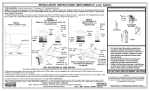
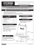
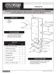
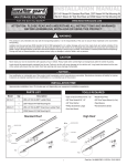
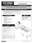
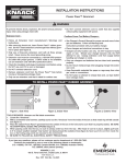
ASSEMBLY AND INSTALLATION INSTRUCTIONS JOBMASTER® Rolling Work Bench - Models 40 & 44 Hole Plugs Push Handle DANGER 5/16-18 x 3/4" Truss Hd. Bolt 5/16-18 x 3/4" Truss Head Bolt 5/16-18 Whiz Lock Nut Door Handle IMPORTANT BEFORE YOU BEGIN Read these instructions and warnings completely before installation. CASTER BOLT KIT Bolt kit #32-0001 is provided with your RWB. Check this bolt kit to be sure the following parts are included: Quan. 16 16 16 Description 5/16-18 X 3/4" Carriage Bolt 5/16-18 Whiz Lock Nut 1/4" Pushnut HANDLE / LIFT KNOB KIT 1 2 6 4 1 2 - Push Handle Door Handles 5/16-18 x 3/4" Bolt, Truss hd. 5/16-18 Hex Whiz Nut Lift Knob Hole Plugs PARTS LIST · Work Bench Cabinet · Caster Set with bolt kit · Handle Kit Figure 1. Assembly View WARNING Black knob must be latched in the closed position when moving this product, so doors and drawers do not open on inclines, which can cause serious personal injury or property damage. TOOLS REQUIRED · · · · · 1/2" Open or Box End Wrench 1/2" Socket (3/8" drive) 3/8" Medium Extension 3/8" Ratchet Wrench Screwdriver, common ASSEMBLY INSTRUCTIONS 1. Remove the caster box, handles, and bolt kit from the cabinet. Attach the Door Handles (Figure 1.). Insert Hole Plugs in the Push Handle and attach to the end. Do not put fuels, flammables, explosives or hazardous materials inside these products. Gasoline, solvents, gun powder or other munitions, dynamite, propane, acetylene or other such products can explode if stored inside these products. Use these products ONLY for storing and transporting electric or hand tools and equipment, and other similar materials. Failure to follow these warnings or modification or other uses of these products could result in death, serious injury or property damage. CAUTION Caster Brakes are not suitable for keeping units in place when transporting. Secure by another method. Do not use casters on rough or uneven surfaces. Do not tow caster mounted boxes. Caster Set Installation 2. Close the doors and lay the cabinet on its back onto the flattened shipping carton to prevent paint scratches (Figure 2.). Mount the Swivel Casters on end you mounted the Push Handle. Insert a Carriage Bolt into a mounting hole, and push a Pushnut onto the bolt to hold it in place (Figure 3). Repeat this for the other three mounting bolts. Place the Caster over the bolts, then fasten WATCHMAN® III Lock System IMPORTANT: Carefully follow the separate instructions (see inside door) which will guide you to a proper lock installation. Rev F 11/00 Part No. 14-4044 4. When right and left slides are in place, extend fully. Next, push rear pocket on drawer onto rear clip on CAUTION Pull out only one drawer at a time to avoid sudden tipping of product which could cause serious personal injury or property damage. Figure 2. Caster Mounting Holes 5. Take one slide and insert rear clip into rear notch, and lower front clip into front notch (See Figure 5.). with Whiz Nuts. Repeat this for the remaining Casters. Drawer Removal Drawer Slide Removal Figure 4. Upper Drawer Removal 3. To remove a drawer (Figure 4.), pull the drawer out until it stops. Notice the locking levers located inside the track that is attached to the drawer. Lift the left lever (A) slide and lower front pocket onto front clip. Close the drawer completely. The mechanism will automatically latch. 6. Reverse step 5. Drawer Slide Installation 5/16-18 x 3/4" Carriage Bolt FRONT VIEW 1/4" Pushnut Figure 5. Drawer Slide Installation 5/16-18 Whiz Nut Figure 3. Caster Mounting while pressing down on the right lever (B). Pull drawer clear on the slides. Drawer Installation DRAWER MEMBER CABINET MEMBER SIDE VIEW FRONT REAR CABINET MEMBER -NOTICE- Any modification or unintended use of this product shall immediately void all manufacturers warranties. Manufacturer disclaims all liability for injuries to persons or property resulting from any modification to, or unintended use of this product. If you have any questions, please give us a call. Call Toll Free 1-800-456-7865 Knaack® products are protected by one or more of the following patents or trademarks: U.S. - 5076078, 1182980, 1182981, 1182982, 1182983, 1517767, 1560477, 1897535, 945736; Canada - 280058, 283281, 281398; U.K. - 2233036, 1390299; Aus - 754070, 754069; N.Z. - 296048, 296050 other patents pending. KNAACK MANUFACTURING COMPANY 420 E. TERRA COTTA AVENUE - CRYSTAL LAKE, ILLINOIS, 60014 815-459-6020 ©2000 Knaack Manufacturing Company