1
Always the Better Idea.
English
Model 1201
ModéleModéle 1201
1211
Français
Safety Warning:Always wear safety glasses or eye shields before
commencing power tool operation. Follow your manufacturer’s
instructions for safety when using this attachment. Always keep
hands at a safe distance from spindles and cutting tools. Always
disconnect power source before working with power tools.
Avertissement de sécurité :Toujours porter des lunettes de
sécurité ou un masque facial lors de l’utilisation de l’outil. Lorsque
cet accessoire est utilisé, suivre les instructions de sécurité du
fabricant. Toujours garder les mains à l’écart des broches et outils
de coupe. Toujours débrancher l’outil avant d’installer l’accessoire.
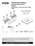
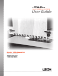
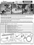
Assembling and Centering TurnLock™ Base Plate
Monter et centrer la semelle TurnLock™
Remove power source from router.
Débrancher l’alimentation électrique de la défonceuse.
1
2
Remove existing base from router by removing appropriate
screws.
3
Install provided TurnLock Bushing on to the Base Plate by
twisting into the TurnLock opening in the center of Base
Plate.
4
5
Insert appropriate end of the centering pin into router
collet. (Follow your router manufacturer’s instructions for
this step.)
Place the Base Plate so that the screw mounting
recesses are facing away from the router.
After lowering the Base Plate so it is in contact with the
centering pin, rotate the Base Plate over the router’s threaded
screw holes until the correct alignment is found.
NOTE:If you need assistance in aligning the TurnLock base plate
with the screw holes on your router, visit www.milescraft.com for
a Router Compatibility Chart.
1
2
Enlever la semelle existante de la défonceuse en enlevant
les vis appropriées.
3
4
5
Installer la douille TurnLock fournie sur la semelle en tournant
dans l'ouverture TurnLock au centre de la semelle.
Insérer l’extrémité appropriée de la broche de centrage
dans le mandrin à pince. (Suivreles instructions du fabricant
de la défonceuse pour cette étape.)
Placer la semelle de façon à ce que les échancrures des vis
de montage soient tournées à l’opposé de la défonceuse.
Après avoir baissé la semelle de façon à ce qu’elle soit en
contact avec la broche de centrage, faire tourner la semelle
sur les trous de vis filetées de la défonceuse jusqu’à ce
que l’on arrive à l’alignement correct.
&121201
Modelo 1201
11
Modelo
Español
Advertencia de seguridad: Lleve siempre gafas de seguridad o
protectores de ojos antes de empezar la operación con herramientas
eléctricas. Siga las instrucciones de su fabricante referentes a la
seguridad al usar este accesorio. Mantenga siempre las manos a
una distancia segura de los husillos y las herramientas de corte.
Desconecte siempre la fuente de alimentación antes de trabajar
con esta clase de herramientas.
Como ensamblar y centrar la placa base TurnLock™
Desconecte la rebajadora del suministro de electricidad.
1
2
Quite la base existente de la rebajadora desatornillando los
tornillos apropiados.
3
4
5
Instale el cojinete TurnLock en la placa base girándolo en la
abertura del TurnLock en el centro de la placa base.
Inserte el extremo del perno central en el collarín de la
rebajadora. (Para este paso siga las instrucciones del
fabricante de la rebajadora.)
Coloque la placa base de modo que las concavidades para
el montaje de los tornillos queden opuestas a la rebajadora.
Después de bajar la placa base de modo que esté en contacto
con el perno central, rote la placa base sobre los agujeros
roscados para los tornillos de la rebajadora hasta que se
obtenga el alineamiento adecuado.
NOTA :Si on a besoin d'aide pour aligner la semelle TurnLock
avec les trous de vis de la défonceuse, aller à www.milescraft.com
NOTA:Si necesita ayuda para alinear la placa base TurnLock con los
pour le Tableau de Compatibilité Défonceuse.
agujeros para tornillos de la rebajadora, visite www.milescraft.com
para obtener un cuadro de compatibilidad de rebajadoras.
Assembling and Centering TurnLock™ Base Plate • Monter et centrer la semelle TurnLock™ • Como ensamblar y centrar la placa baseTurnLock™
1
2
© 2007 Milescraft • Patent # 7089978 • www. milescraft. com
4
3
1
5
82004
9-07
Model
Modelo
Mod é le
1201
Part
Partie
Parte
Part
Partie
Parte
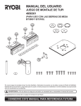
30018
30050
00007
00002
1
1
3
3
1/2”
12.7 mm
15/64”
5.8 mm
30231
1
15/64”
5.8 mm
11/32”
8.7 mm
9/16”
14.2 mm
7/16”
11 mm
5/8”
15.8 mm
30230
11/32”
8.7 mm
13/32”
10.3 mm
9/16”
13.8 mm
5/8”
15.8 mm
7/16”
11 mm
1/2”
12.7 mm
5/8”
15.87 mm
51/64”
20.24 mm
1 30032
1 30034
1 30036
1 30040
1
1/4”
5 mm
5/16”
7 mm
3/8”
8 mm
1/2”
12.7 mm
9/16”
14 mm
5/16”
7 mm
5/16”
7.9 mm
9/16”
14.2 mm
5/16”
7.9 mm
15/32”
12 mm
9/16”
14.2 mm
9/32”
7.1 mm
3/8”
9.56 mm
1 30028
1 30030
3/16”
4.7 mm
5/32”
3.9 mm
1/4”
6.3 mm
MAX
5/16”
7.93 mm
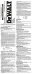
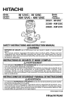
Replacement Part #
Piece De Rechange #
Pieza De Recambio #
30081
1
Quantity
Quantitie
Cantidad
Replacement Part #
Piece De Rechange #
Pieza De Recambio #
Quantity
Quantitie
Cantidad
Part List / Liste des Pieces / Parte Lista
Always the Better Idea.
© 2006 Milescraft (0107) Pat#7089978 www.milescraft.com
DeWalt
Black&Decker
Milwaukee
Bosch
Hitachi
Freud
DeWalt
Craftsman Pro
Makita
Freud
Triton
Craftsman
Craftsman
Porter Cable
Ryobi
DeWalt
1
1
1
1
1
1
2
2
2
2
2
3
4
5
6
7
DW621
R161
PC7301 (Laminate Trimmer)
(315.)275.000
27500
DW616
26835
3606
FT2000E
TRC001
14
5
7, 1
13
DeWalt
Fein
ELU
Bosch
Bosch
Ryobi
13
14
15
Hitachi
11
12
12
12
Festool
10
RE600
1617
1613EVS
DW625
FT-1800
177
M12V
900, 1000, 1010
PO600
963-01 ("Advantage" Plunge Base)
11
4
Bosch
Dremel
2, 3, 8,15
10
11
9
9
10
2, 7
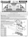
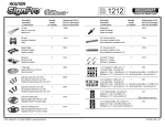
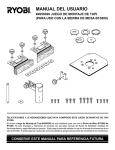
Router Model #'s
RE180PL
6
Mounting
Location Router Brand
8
Ryobi
12
4
Other routers not listed may fit using varied combinations of holes and slots.
In some instances shown above, NOT ALL holes in a router’s base will match the mounting pattern.
Only 2 holes matched to a router’s base are required (as a minimum) for proper installation and operation.
You may decide to modify an existing hole or slot or add a hole(s) to better suit your router.
The screws supplied may not fit your router. If you supply your own screws, DO NOT use “counter sink head” styles.
Check our website... www.milescraft.com for possible revisions.
7 in. Base Plate is included in most Milescraft ® TurnLock™ router products.
(e.g.: 1203 Circle/Edge Guide, 1205 Offset Base, 1206 SignCrafter, 1212 SignPro,1207 Design/Inlay Kit)
A note about TurnLock™ Guide Bushings:
Your TurnLock™ Guide Bushings are injection molded parts designed for a “snug fit”.
Upon first use, you may find the fit to be somewhat tight.
If this is the case:
work the bushing back and forth in the base to “seat” and “work fit” the bushing.
Porter Cable
1
6
1, 5, 14
Router Model #'s
1810-01, 1815-04, 182004,1823, 1825-04, 1840,
1845-02
(315.) 175020, 175040, 175050,
175070, 17574
(09) 17511, 17515, 17528,
17533, 26834
PC690, PC7529, PC8529,
PC890’ PC893PK
DW618, DW610
RP400
5615-29, 5615-21, 5616, 5619
1604, 1618
M12VC
FT1700
13
This is not intended to demonstrate all possible routers that can be used with the Milescraft base plate.
Craftsman
1
Mounting
Location Router Brand
1
Skil
11
14
9, 13
1, 10, 15
4
7
11
2, 3, 7
4, 6, 8
7 IN. TURNLOCK™ ROUTER BASE PLATE MOUNTING KEY
2, 3, 9, 10, 12, 15
#30081