1
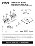
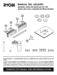
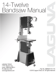
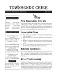
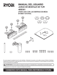
OPERATOR'S MANUAL
#4950300 ROUTER AND JIG SAW MOUNTING KIT
(FOR USE WITH THE BT3000 TABLE SAW)
CONGRATULATIONS AND THANK YOU FOR BUYING THIS RYOBI ROUTER AND JIG SAW MOUNTING KIT.
Your new #4950300 Router and Jig Saw Mounting Kit has been designed for use with the RYOBI BT3000 Table Saw. It
has been engineered and manufactured to Ryobi’s high standards for dependability, ease of operation, and operator safety.
This kit gives you the capability of mounting a router or jig saw on the accessory table of your BT3000. It also includes a circle
cutting jig for cutting circular patterns in both large and small stock. Properly cared for, it will provide years of dependable,
trouble-free performance.
RULES FOR SAFE OPERATION
1.
2.
3.
4.
5.
6.
READ THESE INSTRUCTIONS THOROUGHLY before assembling or using this router and jig saw mounting kit.
READ THE INSTRUCTIONS FOR THE BT3000 TABLE SAW before operating your saw with this kit.
KEEP ASSEMBLY AREA AND WORK AREA CLEAN. Cluttered areas and benches invite accidents.
ALWAYS WEAR SAFETY GLASSES . Everyday eyeglasses have only impact-resistant lenses; they are NOT safety
glasses.
DO NOT USE THIS PRODUCT WITH OTHER EQUIPMENT OR FOR OTHER PURPOSES.
ALWAYS DISCONNECT SAW FROM POWER SUPPLY BEFORE ASSEMBLING THIS KIT. Make sure switch is off
when reconnecting saw to power supply.
Save This Manual For Future Reference
RULES FOR SAFE OPERATION (Continued)
7.
DO NOT MAKE ADJUSTMENTS UNTIL CUTTER OR BLADE HAS COME TO A COMPLETE STOP AND TOOL HAS
BEEN DISCONNECTED FROM POWER SOURCE.
8.
FEED WORKPIECE AGAINST ROTATION OF CUTTER.
9.
DO NOT USE AWKWARD HAND POSITIONS.
10.
KEEP FINGERS AWAY FROM REVOLVING CUTTER, USE FIXTURES WHEN NECESSARY.
11.
WHENEVER POSSIBLE, ALWAYS USE DUST COVER FOR OVERHEAD GUARDING.
12.
DO NOT REMOVE JAMMED CUTOFF PIECES UNTIL CUTTER OR BLADE HAS STOPPED AND TOOL HAS BEEN
DISCONNECTED FROM POWER SOURCE.
13.
HOLD WORKPIECE FIRMLY AGAINST THE TABLE.
14.
UNUSED SAW MAY CAUSE PERSONAL INJURY. DISCONNECT MOTOR CORD FROM THE RECEPTACLE ON
YOUR SAW AND PLUG ACCESSORY POWER CORD INTO THE RECEPTACLE. ALWAYS USE THE SAW'S
MASTER SWITCH TO TURN THE ACCESSORY "ON" AND "OFF".
INTRODUCTION
CHECKING PARTS
As mentioned previously, this kit gives you the capability of
mounting a router or jig saw on the accessory table of your
BT3000. A router mounted on the accessory table will provide expanded capabilities for making rabbets, grooves,
chamfers, dovetails, and mortise and tenon joints. A jig saw
mounted on the accessory table will provide expanded
capabilities for cutting curves, scrollwork, and intricate patterns.
Separate all parts from packing materials. Check your parts
with the parts list on page 3. Refer to Figure 1 if you are
unsure about the description of any part. If any parts are
missing, delay assembly of this kit until you have obtained
the missing part(s).
The circle cutting jig included in this kit enables you to easily
cut circular patterns in both large and small stock with either
a router or jig saw.
Attempting to assemble the Router and Jig Saw
Mounting kit or to use in any way without obtaining any
missing parts and installing them correctly, could result
in an accident resulting in possible serious injury.
The additional versatility gained from use of this kit will turn
your BT3000 table saw into a remarkable woodshaping
center.
IMPORTANT NOTE
This router kit has been specifically designed for use with the
Ryobi Model RE600 Electronic Router Only. The hole
pattern on the mounting plate has not been drilled to
accommodate other routers on the market.
This jig saw kit is used to mount a jig saw on the accessory
table of your BT3000 table saw. Ryobi jig saws plus many
other brands can be mounted using the parts supplied in this
kit. Before operating the jig saw, make sure the front and rear
clamping brackets properly secure the jig saw base to the
mounting plate. Care must be taken to insure that the jig saw
blade does not come in contact with the throat plate, accessory
table, or any part of the assembly during operation. Visually
inspect all areas of moving parts prior to connecting the jig
saw to power supply.
WARNING:
TOOLS NEEDED
Tools needed for assembly of this kit are a phillips screwdriver, two slotted screwdrivers, and an adjustable wrench.
Note: Adjustable wrench will be used to tighten threaded
post into the special 5/16 in. T-nut provided.
WARNING:
Unplug the power supply cord of your BT3000 from
electrical outlet before you begin mounting this kit. It
should remain disconnected until the mounting operation
is complete, all attachments are installed properly, and
they have been checked to make sure they are secure.
Failure to unplug your saw could result in accidental
starting causing possible serious personal injury.
UNPACKING
Your new router and jig saw mounting kit includes two
separate mounting plates, two guide fences with guide
blocks, a dust cover assembly, a throat plate, plus the
necessary brackets and connecting hardware required to
mount a Ryobi Model RE600 Electronic Router to the
accessory table of your BT3000 table saw. It also includes
connecting hardware required to mount Ryobi jig saws to the
accessory table of your BT3000 table saw .
Page 2
THROAT PLATE
5/16 in. WASHERS
KNOB BOLTS
GUIDE FENCE
WITH GUIDE BLOCK
JIG SAW
MOUNTING PLATE
#10-24 SCREWS
TABLE
CLAMPING
BRACKET
REAR
CLAMPING
BRACKET
FRONT
CLAMPING BRACKET
5/16 in. T-NUTS
KNOB BOLT
5/16 in. WASHER
#6 WOOD SCREW
ROUTER
MOUNTING PLATE
CIRCLE
CUTTING COLLAR
SPACER
POST
#10 WASHER
#1/4-20 SCREWS
DUST COVER WITH PIVOT ASSEMBLY
Fig. 1
LIST OF LOOSE PARTS
Your #4950300 Router and Jig Saw Mounting Kit includes the following parts:
DESCRIPTION
QUANTITY
DESCRIPTION
QUANTITY
Jig Saw Mounting Plate ........................................... 1
Screw (#10-24 x 3/4 in. Phillips Flat Hd.) ................ 4
Router Mounting Plate ............................................ 1
Screw (#1/4-20 x 1/2 in. Phillips Flat Hd.) ............... 4
Circle Cutting Collar with Slot.................................. 1
Washer (#10) ........................................................... 1
Screw (#10-24 x 1 in. Round Hd.) ........................... 1
Wood Screw (#6 x 1 in. Round Hd.) ....................... 1
Table Clamping Bracket .......................................... 1
Knob Bolt (#5/16-18 x 3/4 in.) ................................. 1
Guide Fence with Guide Block ................................ 2
Knob Bolt (#5/16-18 x 1/2 in.) ................................. 4
5/16" Washer ........................................................... 5
5/16" T-Nut (Special) ............................................... 6
Spacer ..................................................................... 1
Post ......................................................................... 1
Dust Cover with Pivot Assembly ............................. 1
Throat Plate ............................................................. 1
Front Clamping Bracket for Jig Saw ....................... 1
Rear Clamping Bracket for Jig Saw ........................ 1
Page 3
ASSEMBLY
Read these instructions completely before beginning assembly of this kit.
ROUTER MOUNTING
T-NUT SHOWN BETWEEN ADJUSTMENT SCREWS
WARNING:
The saw's motor cord must be disconnected from the
receptacle provided on the saw when using this kit with
a Router or Jig Saw mounted to the accessory table.
The power supply cord of the Router or Jig Saw must be
plugged into the receptacle and the saw's master switch
must be used to turn the Router or Jig Saw "ON" or
"OFF".
T-NUT
ADJUSTMENT
SCREW
IMPORTANT
This router kit has been specifically designed for use with the
Ryobi Model RE600 Electronic Router Only. The hole
pattern on the mounting plate has not been drilled to
accommodate other routers on the market. Special mounting
screws are provided with the RE600 to insure safe, secure
mounting.
WASHER
TO INSTALL T-NUTS FOR GUIDE FENCE
BRACKETS
See Figure 2.
This kit requires that five of the special 5/16 in. T-nuts
provided fit in the top channel of the rip fence on your BT3000
table saw. The first T-nut is required between the two
adjustment screws on top of the rip fence.
TO INSTALL:
1. Place rip fence against saw blade as shown in figure 2
and lock in place. This will insure that rip fence remains
square.
2. Using the appropriate allen wrench supplied with your
BT3000 table saw, loosen and remove rear adjustment
screw and washer on top of rip fence.
3. Slide one of the special 5/16 in. T-nuts into top channel
of rip fence and place it between two adjustment
screws. Note: T-nuts install from rear of rip fence.
RIP FENCE SHOWN
LOCKED AGAINST SAW BLADE
Fig. 2
INSTALL T-NUTS FROM REAR OF RIP FENCE
T-NUT
4. Replace adjustment screw and washer.
5. Tighten adjustment screw securely.
6. Check rip fence for squareness with saw blade.
TO INSTALL REMAINING T-NUTS
See Figure 3.
1. For ease of assembly, unlock rip fence and slide away
from saw blade. See Figure 3.
2. Lock rip fence.
3. Slide four remaining 5/16 in. T-nuts in top channel of rip
fence as shown in figure 3.
Note: You should now have five T-nuts in the top
channel of rip fence. Only one should be between
adjustment screws.
Page 4
Fig. 3
ROUTER MOUNTING (Cont'd)
TO INSTALL GUIDE FENCE BRACKETS
See Figure 4.
1. Align each guide fence bracket with two of the special 5/16 in. T-nuts in channel on top of rip fence.
2. Secure guide fences to rip fence with 5/16 in. washers and 5/16 in. x 1/2 in. knob bolts supplied. Note: As shown in
figure 4, center T-nut is not used with guide fences.
TO INSTALL POST
See Figure 4.
1. Place spacer provided on threaded end of post.
2. Thread post thru spacer into remaining 5/16 in. T-nut in top channel of rip fence.
3. Tighten post securely with an adjustable wrench. Note: Adjustable wrench will fit flats on top of post.
TO INSTALL DUST COVER AND PIVOT ASSEMBLY
See Figure 4.
1. Place dust cover and pivot assembly on post as shown in figure 4.
2. It will slide up and down post as needed. When desired location is achieved, secure it in place by tightening knob nut
attached to carriage bolt.
CARRIAGE BOLT (NOT SHOWN)
DUST COVER AND PIVOT ASSEMBLY
KNOB NUT
FLATS ON POST
POST
KNOB BOLTS
SPACER
5/16 in. WASHERS
T-NUTS
GUIDE FENCE BRACKET
RIP FENCE
Fig. 4
Page 5
ROUTER MOUNTING (Cont'd)
TO ASSEMBLE RE600 ELECTRONIC ROUTER
TO ROUTER MOUNTING PLATE
8 MILLIMETER
SCREWS
See Figures 5 and 6.
1. Remove the subbase screws and subbase from your
router.
2. Figure 5 illustrates the correct orientation of parts and
pieces for mounting your router to its mounting plate.
3. Place router upside down on a workbench and align
mounting plate holes with tapped holes in the base of
your router.
4. The switch handle of router should be facing the squared
end of mounting plate. See Figure 5.
5. Using the 8 mm flat head screws provided with your
router, secure mounting plate to router.
6. Once properly assembled, your router and mounting
plate assembly should be similar to the illustration
shown in figure 6.
7. Tighten screws securely.
RE600
ELECTRONIC
ROUTER
ROUTER
MOUNTING
PLATE
FRONT OF ROUTER
TO ASSEMBLE MOUNTING PLATE WITH
ROUTER ATTACHED TO ACCESSORY TABLE
Fig. 5
See Figure 7.
1. Place mounting plate under accessory table as shown
in figure 7. Note: If desired you can remove accessory
table, attach mounting plate with router, then reassemble
complete assembly to your saw.
2. Secure mounting plate to accessory table using the four
#1/4-20 x 1/2 in. flat head screws provided.
3. Tighten screws securely.
INSTALLING ROUTER BIT
Follow the instructions in the operator's manual of your router
for this procedure. Install router bit and tighten securely in
collet.
Fig. 6
THROAT PLATE
#1/4-20 SCREWS
CAUTION:
ACCESSORY TABLE
Check to make sure it will not strike the accessory table or
any metal surface.
TO ASSEMBLE THROAT PLATE
See Figure 7.
Orient the throat plate as shown in figure 7, align tab with slot
in accessory table, then place throat plate in recessed area
of accessory table. Recheck router bit to make sure it will
not strike the throat plate.
SLOT
TO ASSEMBLE TABLE CLAMPING BRACKET
See Figure 8.
The lever on the accessory table will tighten it securely to the
front rail of your BT3000. However, the weight of your router
and mounting plate, etc. may cause accessory table to be
loose or have movement at the rear of the accessory table.
To avoid this, install the table clamping bracket supplied with
this kit. It can be used with a router mounted, with a jig saw
mounted, or if desired it can be used with your BT3000 during
normal use.
Page 6
ROUTER
WITH MOUNTING
PLATE ATTACHED
Fig. 7
ROUTER MOUNTING (Cont'd)
TO ASSEMBLE TABLE CLAMPING BRACKET
(Cont'd)
TABLE CLAMPING BRACKET
SHOWN COMPLETELY ASSEMBLED
1. Remove end cap from rear rail as shown in figure 8.
2. Slide one of the special 5/16 in. T-nuts into channel of
rear rail.
3. Orient table clamping bracket as shown and secure
with a 5/16 in. washer and 5/16-18 x 3/4 in. knob bolt.
Note: Table clamping bracket fits in bottom slot of rear
rail. The slotted top of this bracket wraps around the
raised portion on the underside of the accessory table,
clamping it tightly against the rear rail.
4. Tighten knob bolt securely.
5. Reassemble end cap to rear rail.
FINAL ASSEMBLY
See Figure 9.
After all router mounting parts have been assembled, your
set-up should be similar to the illustration shown in figure 9.
1. Compare your set-up to the set-up shown in figure 9 and
make any necessary adjustments.
2. Recheck all knob bolts, loose parts, etc. and securely
tighten if necessary.
ACCESSORY TABLE
TABLE
CLAMPING BRACKET
END CAP
PREPARING FOR OPERATION
T-NUT
See Figure 9.
1. Adjust dust cover so that it will not come in contact with
workpiece during cutting operation.
2. Direction of feed of workpiece is from right to left as
shown by the arrow in figure 9.
3. Direction of feed must always be so that the workpiece
is being thrust against the sharp edges of rotating bit.
4. Workpiece must always be tight against guide fence.
Infeed fence should be adjusted to support uncut
workpiece while the outfeed fence should be adjusted
properly to support the workpiece after the cut passes
the router bit.
ROUTER KIT SHOWN COMPLETELY ASSEMBLED
REAR RAIL
5/16 in. WASHER
KNOB BOLT
Fig. 8
DIRECTION OF FEED IS FROM RIGHT TO LEFT
AGAINST SHARP EDGES OF ROTATING BIT
Fig. 9
Page 7
JIG SAW MOUNTING
When used for jig saw mounting, this kit can be used with all
Ryobi jig saws, plus most other brands of jig saws. Proper
mounting of the jig saw base to the clamping brackets will
determine which saws will work. The jig saw must be mounted
securely for safety.
6. Place mounting plate upside down on a flat workbench
and position jig saw under front and rear clamping
brackets. We suggest that you tilt your saw forward and
slide front of base under front clamping bracket. Next,
lower rear of jig saw down on mounting plate and place
rear bracket on rear of saw base.
TO ASSEMBLE JIG SAW TO MOUNTING PLATE
7. Carefully invert this set-up and snugly tighten clamping
bracket screws.
See Figure 10.
1. Figure 10 illustrates the correct orientation of parts and
pieces for mounting your jig saw to its mounting plate.
2. The front of jig saw should be facing the squared end of
mounting plate, while the rear of saw faces mitered
corners.
TO ADJUST JIG SAW ON MOUNTING PLATE
See Figure 11.
3. The front clamping bracket (formed bracket) mounts on
the squared end of mounting plate. Therefore, front
clamping bracket will secure front of jig saw base to
mounting plate.
4. The rear clamping bracket (flat bracket) mounts on the
end with mitered corners and secures rear of jig saw
base to mounting plate.
Hint:
5. Loosely attach front and rear clamping brackets to
mounting plate using the #10-24 x 3/4 in. flat head
screws provided. Note: Thread head of screws thru
countersunk side of mounting plate.
JIG SAW
MOUNTING PLATE
#10-24 SCREWS
1. Once properly assembled and adjusted, your jig saw
and mounting plate assembly should be similar to the
illustration shown in figure 11.
2. If adjustments are required, loosen clamping bracket
screws and adjust jig saw as needed.
3. We suggest that you always begin by sliding screws to
the rear of front slot in mounting plate and adjust as
needed. This will prevent saw blade from coming in
contact with the throat plate, mounting plate, accessory
table, etc. when installed.
4. After all adjustments have been made, tighten clamping
bracket screws securely.
#10-24 SCREWS
(CLAMPING BRACKET SCREWS)
REAR SLOT
REAR
CLAMPING
BRACKET
JIG SAW
BASE
FRONT SLOT
FRONT
CLAMPING
BRACKET
JIG SAW
Fig. 10
Fig. 11
Page 8
JIG SAW MOUNTING (Cont'd)
TO ASSEMBLE MOUNTING PLATE WITH JIG SAW ATTACHED TO ACCESSORY TABLE
See Figure 12.
1. Place mounting plate under accessory table as shown in figure 12. Note: If desired you can remove accessory table,
attach mounting plate with jig saw, then reassemble complete assembly to your saw.
2. Secure mounting plate to accessory table using the four #1/4-20 x 1/2 in. flat head screws provided.
3. Tighten screws securely.
INSTALLING SAW BLADE
Follow the instructions in the operator's manual of your jig saw for this procedure. Install the blade and tighten it securely.
CAUTION:
Check to make sure it is not striking the accessory table or any metal surface.
TO ASSEMBLE THROAT PLATE
See Figure 12.
Orient the throat plate as shown in figure 12, align tab with slot in accessory table, then place throat plate in recessed area
of accessory table. Recheck the saw blade to make sure it will not strike the throat plate.
THROAT PLATE
#1/4-20 SCREWS
ACCESSORY TABLE
TAB
SLOT
JIG SAW WITH MOUNTING PLATE ATTACHED
Fig. 12
REMEMBER:
The motor cord of your BT3000 saw should be unplugged from receptacle on side of cabinet; and the power supply
cord of your router or jig saw should be plugged into receptacle. This will allow your router or jig saw to be controlled
by the master switch of your saw.
Page 9
CIRCLE CUTTING JIG
CIRCLE CUTTING
See Figures 13-16.
#10-24 MACHINE SCREW
The circle cutting jig makes it possible to cut and shape
circular patterns in both large and small stock. The smallest
circle that can be made is approximately 8 in. in diameter.
Note: There are many variables that influence the size of a
circle being cut or shaped. The set-up you make, the location
of the circle cutting collar, whether you drill a hole and use the
machine screw, or whether you use a wood screw are a few
examples of factors that influence the size and shape of a
circle.
#10 WASHER
WORKPIECE
3/16 in. HOLE
CIRCLE CUTTING COLLAR
See Figures 13-16.
The circle cutting collar mounts on the bottom, center of
workpiece, with either the machine screw and washer or the
wood screw supplied. It then mounts on the sliding miter table
in one of the two holes used for the locator pin on the bottom
of miter fence (The operator's manual for your BT3000 refers
to them as hole "A" and hole "B").
CIRCLE
CUTTING COLLAR
PILOT HOLE
CIRCLE CUTTING SET-UP WITH MACHINE
SCREW
See Figure 13 .
SLOTTED END OF CIRCLE CUTTING COLLAR
To make set-up:
1. Drill a 3/16 in. hole in center of workpiece for machine
screw.
2. Place the machine screw and washer thru the top of
workpiece.
3. Secure to circle cutting collar on the bottom of workpiece.
Note: Slotted end of circle cutting collar should be
turned away from workpiece as shown. A screwdriver
can then be used to tighten screw securely.
4. If applicable, drill pilot hole in workpiece for jig saw
blade or router bit.
Fig. 13
#6 WOOD SCREW
CIRCLE
CUTTING COLLAR
CIRCLE CUTTING SET-UP WITH WOOD SCREW
See Figure 14.
To make set-up:
1. Place workpiece upside down on a flat workbench.
2. Locate center of workpiece as shown in figure 14.
3. Place #6 x 1 in. wood screw thru circle cutting collar and
thread into bottom of workpiece. Note: Check thickness
of workpiece before threading screw into workpiece.
Be careful not to let screw penetrate top surface of thin
workpieces.
4. If applicable, drill pilot hole in workpiece for jig saw
blade or router bit.
Page 10
PILOT HOLE
WORKPIECE SHOWN UPSIDE DOWN
Fig. 14
CIRCLE CUTTING JIG (Cont'd)
TO PLACE WORKPIECE ON SAW TABLES
See Figure 15.
As mentioned previously there are many variables that influence a circle being cut or shaped. These variables must be
considered when placing workpiece on saw tables to begin a cut. The sliding miter table and accessory table must both be
used when making a cut or shaping. Also the rails may need to be adjusted, according to the application and size of the
workpiece. For large workpieces, the sliding miter table may need to be placed on the left side of the saw blade. In these
situations, the saw blade will need to be lowered below the table surface and the blade guard assembly removed. You will learn
from experience how to best make these set-ups.
For illustration purposes, we have shown the sliding miter table beside the accessory table. The rails have been moved
enough for both tables and the workpiece to fit on the right side of the saw blade.
1. Place workpiece with circle cutting collar attached on sliding miter table. Align the circle cutting collar with one of the holes
in sliding miter table and place it in position. See Figure 15.
2. Adjust accessory table so that saw blade or router bit are aligned with pilot hole in workpiece.
3. Securely tighten sliding miter table and accessory table to rails.
4. Lock the sliding miter table by engaging the lock tab in the appropriate slot on the miter table base.
COMPLETED SET-UP FOR CIRCLE CUTTING
See Figure 16.
After completing set-up for circle cutting, it should be similar to the illustration shown in figure 16. Recheck all necessary steps.
Also recheck screws, tables, etc. for tightness.
WORKPIECE WITH CIRCLE
CUTTING COLLAR ATTACHED
SLIDING
MITER TABLE
JIG SAW BLADE
PILOT HOLE
ACCESSORY TABLE
SLOT
DIRECTION OF FEED
LOCK TAB
PILOT HOLE
PLACE CIRCLE CUTTING COLLAR IN HOLE
JIG SAW KIT SHOWN COMPLETELY ASSEMBLED
Fig. 15
Page 11
Fig. 16
#4950300 ROUTER AND JIG SAW MOUNTING KIT
5
6
3
8
7
4
5
3
4
2
11
10
1
9
12
3
4
13
14 15
19
20
16
18
17
23
25
24
22
21
Page 12
REPLACEMENT PARTS
Now that you have purchased your Router and Jig Saw Mounting Kit, should a need ever exist for repair
parts or service, simply contact your nearest Ryobi Authorized Service Center or other qualified service
organization. Be sure to provide all pertinent facts when you call or visit.
PARTS LIST
KEY
NO.
1
2
3
4
5
6
7
8
9
10
11
12
13
14
15
16
17
18
19
20
21
22
23
24
25
DESCRIPTION
QUANTITY
Guide Block ................................................................................................................................ 2
Guide Fence ............................................................................................................................... 2
Wood Screw (#10 x 5/8 in. Round Hd.) ...................................................................................... 4
5/16 in. Washer ........................................................................................................................... 5
Knob Bolt (#5/16-18 x 1/2 in.) ..................................................................................................... 4
Throat Plate ................................................................................................................................ 1
Jig Saw Mounting Plate .............................................................................................................. 1
Screw (#10-24 x 3/4 in. Phillips Flat Hd.) ................................................................................... 4
Rear Clamping Bracket for Jig Saw ........................................................................................... 1
Front Clamping Bracket for Jig Saw ........................................................................................... 1
5/16 in. T-Nut (Special) ............................................................................................................... 6
Table Clamping Bracket ............................................................................................................. 1
Screw (#1/4-20 x 1/2 in. Phillips Flat Hd.) ..................................................................................4
Wood Screw (#6 x 1 in. Round Hd.) ........................................................................................... 1
Screw (#10-24 x 1 in. Round Hd.) .............................................................................................. 1
Circle Cutting Collar with Slot ..................................................................................................... 1
Washer (#10) .............................................................................................................................. 1
Router Mounting Plate ................................................................................................................ 1
Knob Bolt (#5/16-18 x 3/4 in.) ..................................................................................................... 1
Carriage Bolt (#1/4-20 x 1-9/16 in.) ............................................................................................ 1
Dust Cover with Decal ................................................................................................................ 1
Dust Cover Pivot ......................................................................................................................... 1
Knob Nut (#1/4-20 x 1-3/4 in. Dia.) ............................................................................................. 1
Post ............................................................................................................................................. 1
Spacer ........................................................................................................................................ 1
Operator's Manual
Page 13
OPERATOR'S MANUAL
#4950300 ROUTER AND JIG SAW MOUNTING KIT
(FOR USE WITH THE BT3000 TABLE SAW)
RYOBI TECHNOLOGIES INC.
1428 Pearman Dairy Road Anderson SC 29625
Post Office Box 1207 Anderson SC 29622-1207
Phone 1-800-525-2579
612547-852