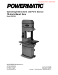
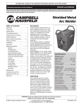
1
This .pdf document is bookmarked Operating Instructions and Parts Manual XACTA® Saw Deluxe WALTER MEIER (Manufacturing) Inc. 427 New Sanford Road LaVergne, Tennessee 37086 Ph.: 800-274-6848 www.waltermeier.com Part No. M-708674 Revision D 09/2013 Copyright © 2013 Walter Meier (Manufacturing) Inc. Warranty and Service Walter Meier (Manufacturing) Inc., warrants every product it sells. If one of our tools needs service or repair, one of our Authorized Service Centers located throughout the United States can give you quick service. In most cases, any of these Walter Meier Authorized Service Centers can authorize warranty repair, assist you in obtaining parts, or perform routine maintenance and major repair on your JET® tools. For the name of an Authorized Service Center in your area call 1-800-274-6848. MORE INFORMATION Walter Meier is consistently adding new products to the line. For complete, up-to-date product information, check with your local Walter Meier distributor, or visit waltermeier.com. WARRANTY JET products carry a limited warranty which varies in duration based upon the product (MW = Metalworking, WW = Woodworking). WHAT IS COVERED? This warranty covers any defects in workmanship or materials subject to the exceptions stated below. Cutting tools, abrasives and other consumables are excluded from warranty coverage. WHO IS COVERED? This warranty covers only the initial purchaser of the product. WHAT IS THE PERIOD OF COVERAGE? The general JET warranty lasts for the time period specified in the product literature of each product. WHAT IS NOT COVERED? Five Year Warranties do not cover woodworking (WW) products used for commercial, industrial or educational purposes. Woodworking products with Five Year Warranties that are used for commercial, industrial or education purposes revert to a One Year Warranty. This warranty does not cover defects due directly or indirectly to misuse, abuse, negligence or accidents, normal wear-and-tear, improper repair or alterations, or lack of maintenance. HOW TO GET SERVICE The product or part must be returned for examination, postage prepaid, to a location designated by us. For the name of the location nearest you, please call 1-800-274-6848. You must provide proof of initial purchase date and an explanation of the complaint must accompany the merchandise. If our inspection discloses a defect, we will repair or replace the product, or refund the purchase price, at our option. We will return the repaired product or replacement at our expense unless it is determined by us that there is no defect, or that the defect resulted from causes not within the scope of our warranty in which case we will, at your direction, dispose of or return the product. In the event you choose to have the product returned, you will be responsible for the shipping and handling costs of the return. HOW STATE LAW APPLIES This warranty gives you specific legal rights; you may also have other rights which vary from state to state. LIMITATIONS ON THIS WARRANTY WALTER MEIER (MANUFACTURING) INC., LIMITS ALL IMPLIED WARRANTIES TO THE PERIOD OF THE LIMITED WARRANTY FOR EACH PRODUCT. EXCEPT AS STATED HEREIN, ANY IMPLIED WARRANTIES OR MERCHANTABILITY AND FITNESS ARE EXCLUDED. SOME STATES DO NOT ALLOW LIMITATIONS ON HOW LONG THE IMPLIED WARRANTY LASTS, SO THE ABOVE LIMITATION MAY NOT APPLY TO YOU. WALTER MEIER SHALL IN NO EVENT BE LIABLE FOR DEATH, INJURIES TO PERSONS OR PROPERTY, OR FOR INCIDENTAL, CONTINGENT, SPECIAL, OR CONSEQUENTIAL DAMAGES ARISING FROM THE USE OF OUR PRODUCTS. SOME STATES DO NOT ALLOW THE EXCLUSION OR LIMITATION OF INCIDENTAL OR CONSEQUENTIAL DAMAGES, SO THE ABOVE LIMITATION OR EXCLUSION MAY NOT APPLY TO YOU. Walter Meier sells through distributors only. The specifications in Walter Meier catalogs are given as general information and are not binding. Members of Walter Meier reserve the right to effect at any time, without prior notice, those alterations to parts, fittings, and accessory equipment which they may deem necessary for any reason whatsoever. JET® branded products are not sold in Canada by Walter Meier. 2 Table of Contents Warranty and Service .............................................................................................................................. 2 Table of Contents .................................................................................................................................... 3 Warnings ................................................................................................................................................. 4 Introduction ............................................................................................................................................. 6 Specifications .......................................................................................................................................... 6 Shipping Contents ................................................................................................................................... 7 Unpacking............................................................................................................................................ 7 Cleaning .............................................................................................................................................. 7 Contents of the Shipping Container ...................................................................................................... 8 Assembly ................................................................................................................................................ 9 Motor Cover ......................................................................................................................................... 9 Handwheel Assembly........................................................................................................................... 9 Miter Gauge and Fence Storage Hooks................................................................................................ 9 Extension Wing .................................................................................................................................. 10 Blade Installation/Replacement .......................................................................................................... 10 Riving Knife and Guard Installation..................................................................................................... 11 Mounting Rails & Extension Table ...................................................................................................... 12 Switch Installation .............................................................................................................................. 12 Electrical Connections ........................................................................................................................... 12 Adjustments .......................................................................................................................................... 13 Handwheel Adjustments..................................................................................................................... 13 Insert Adjustment ............................................................................................................................... 13 Miter Gauge ....................................................................................................................................... 13 Riving Knife Adjustment ..................................................................................................................... 14 Blade Alignment ................................................................................................................................. 15 Adjusting 45° and 90° Positive Stops.................................................................................................. 15 Changing the Belt .............................................................................................................................. 16 Maintenance.......................................................................................................................................... 17 Cleaning ............................................................................................................................................ 17 Lubrication ......................................................................................................................................... 17 Miscellaneous .................................................................................................................................... 17 Troubleshooting..................................................................................................................................... 18 Optional Accessories ............................................................................................................................. 19 Parts ..................................................................................................................................................... 19 Ordering Replacement Parts .............................................................................................................. 19 Table & Cabinet Parts List .................................................................................................................. 20 Trunnion & Motor Parts List ................................................................................................................ 23 Trunnion & Motor Assembly Drawing.................................................................................................. 25 Blade Guard Parts and Assembly....................................................................................................... 26 Wiring Diagrams .................................................................................................................................... 27 The specifications in this manual are given as general information and are not binding. Walter Meier (Manufacturing) Inc., reserves the right to effect, at any time and without prior notice, changes or alterations to parts, fittings, and accessory equipment deemed necessary for any reason whatsoever. 3 Warnings 1. Read and understand the entire owner's manual before attempting assembly or operation. 2. Read and understand the warnings posted on the machine and in this manual. Failure to comply with all of these warnings may cause serious injury. 3. Replace the warning labels if they become obscured or removed. 4. This table saw is designed and intended for use by properly trained and experienced personnel only. If you are not familiar with the proper and safe operation of a table saw, do not use until proper training and knowledge have been obtained. 5. Do not use this table saw for other than its intended use. If used for other purposes, Walter Meier (Manufacturing) Inc., disclaims any real or implied warranty and holds itself harmless from any injury that may result from that use. 6. Always wear approved safety glasses/face shields while using this table saw. Everyday eyeglasses only have impact resistant lenses; they are not safety glasses. 7. Before operating this table saw, remove tie, rings, watches and other jewelry, and roll sleeves up past the elbows. Remove all loose clothing and confine long hair. Non-slip footwear or anti-skid floor strips are recommended. Do not wear gloves. 8. Wear ear protectors (plugs or muffs) during extended periods of operation. 9. Some dust created by power sanding, sawing, grinding, drilling and other construction activities contain chemicals known to cause cancer, birth defects or other reproductive harm. Some examples of these chemicals are: • Lead from lead based paint. • • Crystalline silica from bricks, cement and other masonry products. Arsenic and chromium from chemically treated lumber. Your risk of exposure varies, depending on how often you do this type of work. To reduce your exposure to these chemicals, work in a well-ventilated area and work with approved safety equipment, such as face or dust masks that are specifically designed to filter out microscopic particles. 10. Do not operate this machine while tired or under the influence of drugs, alcohol or any medication. 11. Make certain the machine is properly grounded. 12. Make all machine adjustments or maintenance with the machine unplugged from the power source. A machine under repair should be RED TAGGED to show it must not be used until maintenance is complete. 13. Remove adjusting keys and wrenches. Form a habit of checking to see that keys and adjusting wrenches are removed from the machine before turning it on. 14. Keep safety guards in place at all times when the machine is in use. If removed for maintenance purposes, use extreme caution and replace the guards immediately after maintenance is complete. 15. Check the alignment of the riving knife, fence and miter slot to the blade. A caution decal is installed on each guard to remind the operator of the dangers of improper machine operation. 16. Check damaged parts. Before further use of the machine, a guard or other part that is damaged should be carefully checked to determine that it will operate properly and perform its intended function. Check for alignment of moving parts, binding of moving parts, breakage of parts, mounting and any other conditions that may affect its operation. A guard or other part that is damaged should be properly repaired or replaced. 17. Provide for adequate space surrounding work area and non-glare, overhead lighting. 18. Keep the floor around the machine clean and free of scrap material, oil and grease. 4 19. Keep visitors a safe distance from the work area. Keep children away. 20. Make your workshop child proof with padlocks, master switches or by removing safety keys. 21. Give your work undivided attention. Looking around, carrying on a conversation and “horse-play” are careless acts that can result in serious injury. 22. Maintain a balanced stance at all times so that you do not fall or lean against the blade or other moving parts. Do not overreach or use excessive force to perform any machine operation. 23. Use the right tool at the correct speed and feed rate. Do not force a tool or attachment to do a job for which it was not designed. The right tool will do the job better and safer. 24. Use recommended accessories; improper accessories may be hazardous. 25. Maintain tools with care. Keep blade sharp and clean for the best and safest performance. Follow instructions for lubricating and changing accessories. 26. Check the saw blade for cracks or missing teeth. Do not use a cracked or dull blade or one with missing teeth or improper set. Make sure the blade is securely locked on the arbor. 27. Keep hands clear of the blade area. Do not reach past the blade to clear parts or scrap with the saw blade running. Never saw freehand. Avoid awkward operations and hand positions where a sudden slip could cause your hand to contact the blade. 28. Do not attempt to saw boards with loose knots or with nails or other foreign material, on its surface. Do not attempt to saw twisted, warped, bowed or “in wind” stock unless one edge has been jointed for guiding purposes prior to sawing. 29. Do not attempt to saw long or wide boards unsupported where spring or weight could cause the board to shift position. 30. Always use the riving knife, blade guard, push stick and other safety devices for all operations where they can be used. On operations such as dadoing or molding where the blade guard cannot be used, use feather boards, fixtures and other safety devices and use extreme caution. Reinstall the riving knife and blade guard immediately after completing the operation that required their removal. 31. Be sure the saw blade rotates clockwise when viewed from the motor side (left side) of the machine. 32. Turn off the machine before cleaning. Use a brush or compressed air to remove chips or debris — do not use your hands. 33. Do not stand on the machine. Serious injury could occur if the machine tips over. 34. Never leave the machine running unattended. Turn the power off and do not leave the machine until it comes to a complete stop. 35. Remove loose items and unnecessary work pieces from the area before starting the machine. Familiarize yourself with the following safety notices used in this manual: This means that if precautions are not heeded, it may result in minor injury and/or possible machine damage. This means that if precautions are not heeded, it may result in serious injury or possibly even death. 5 Introduction The JET XACTA® Saw Deluxe table saw you have purchased is a high quality machine tool that will give you years of superior service. You will get maximum performance and enjoyment from your new table saw if you will take a few moments now to review the entire manual before beginning assembly and operation. This table saw, as well as all JET products, are backed by a nationwide network of authorized distributors and/or service centers. Please contact your nearest distributor should you require parts or service. Parts are also available directly from Walter Meier (Manufacturing) Inc., by calling 1-800-274-6848. Now that you have purchased a table saw, it is a good time to consider a dust collection system. See your local JET distributor for the complete line of dust collectors and the full line of JET Dust Collector Hoses and Accessories. Customize your installation and obtain maximum performance with JET's dust hoods, hoses, clamps, fittings, and blast gates. Assembling and fine tuning a table saw, fence and rail system, extension tables, etc. can be a time consuming project. It is best not to rush. The table saw does not come with a plug. Purchase a plug that matches the 230V or 460V outlet that will be used. The table saw does not come with a blade so you may want to purchase a variety of blades for different applications. Specifications Stock Number............................................................................................................ 708674 (3 HP, 1 Ph) ........................................................................................................................ 708676 (5 HP, 1 Ph) ........................................................................................................................ 708680 (5 HP, 3 Ph) Blade Diameter..................................................................................................................................... 10” Arbor Diameter .................................................................................................................................... 5/8” Maximum Depth of Cut ........................................................................................................................... 3” Maximum Thickness at 45° Cut ........................................................................................................ 2-1/8” Table in Front of Saw Blade at Maximum Cut ....................................................................................... 10” Maximum Width of Dado.................................................................................................................. 13/16” Maximum Diameter of Dado ................................................................................................................... 8” Dust Port Diameter ................................................................................................................................. 4” Dust Collection Minimum CFM required ............................................................................................... 350 Table Height ......................................................................................................................................... 34” Table Size (with extension) .................................................................................................... 29"D x 42"W Table Size (without extension) ............................................................................................... 29"D x 20”W Arbor Speed ..............................................................................................................................4300 RPM Sound Rating: (without blade) ................................................................................................................ 70 dB at 3 ft. (with 10”x50T blade) ....................................................................................................... 85 dB at 3 ft. Motor SN 708674...................................................................................................... 3HP, 1Ph, 230V only SN 708676..................................................................................................... 5 HP, 1Ph, 230V only SN 708680................................................... 5HP, 3Ph, 230/460V, prewired 230V (see Note below) Weight Net ....................................................................................................................................... 330lbs. Gross.................................................................................................................................... 407lbs. Note: For 460V operation, magnetic switch (Part No. JTAS10-23B) must be purchased separately and installed. A qualified electrician is recommended. The above specifications were current at the time this manual was published, but because of our policy of continuous improvement, Walter Meier reserves the right to change specifications at any time and without prior notice, without incurring obligations. 6 Read and understand the entire contents of this manual before attempting assembly or operation! Failure to comply may cause serious injury. Shipping Contents Unpacking Remove box and wood crating completely from around saw. Check for shipping damage. Report any damage immediately to your distributor and shipping agent. Do not discard any shipping material until the Table Saw is assembled and running properly. Compare the contents of your container with the parts lists in the next two pages to make sure all parts are intact. Missing parts, if any, should be reported to your distributor. Read the instruction manual thoroughly for assembly, maintenance and safety instructions. 1. Unbolt the saw from the skid. 2. Carefully slide the saw from the pallet onto the floor. Do not connect the tablesaw to the power source until all assembly has been completed! Failure to comply may cause serious injury! The Table Saw should be placed in an area with a sturdy level floor, good ventilation and sufficient lighting. Leave enough space around the machine for mounting extension wings and rail assemblies, and loading and off-loading stock and general maintenance work. Cleaning Exposed metal surfaces, such as the table top and extension wings, have been given a protective coating at the factory. This should be removed with a soft cloth moistened with kerosene. Do not use acetone, gasoline, or lacquer thinner for this purpose. Do not use solvents on plastic parts, and do not use an abrasive pad because it may scratch the surfaces. 7 Contents of the Shipping Container Small Box Main Saw Container 1 1 1 1 1 The small box consists of the following items: Table Saw (A) Switch (B) Table Insert (C) Owner's Manual (D) Warranty Card (not shown) 1 1 1 1 2 1 1 1 1 Blade Guard Assembly (E) Riving Knife and Pawl Assembly (F) Handwheel and Swivel Handle (G) Lock Knob (H) Large Hook (J) Small Hook (K) Push Stick (L) Miter Gauge Assembly (M) 27mm Arbor Wrench (N) Main Saw Container Extension Tables Two extension tables are packaged in individual boxes. Contents of the Small Box Hardware 6 1/4 x 5/8 Socket Head Cap Screw (O) 6 1/4 Flat Washer (P) 6 1/4 Lock Washer (Q) Extension Tables Contents of Hardware Bag Side Cover Box 1 Side Cover Contents of Side Cover Box 8 Assembly Motor Cover Referring to Figures 1 and 2: • Tools: 17mm Wrench, 12mm Wrench 1. Remove shipping bracket (A) securing the motor (C) to table. 2. After the shipping bracket has been removed, install the screw (B) back into the motor support bracket. The upper screws will be used to later to hold the extension wing in place. 3. Remove shipping bracket (D) holding switch assembly (E) to table. Do not discard the bracket (D); it will be used to install the switch. Figure 1 4. Remove the remaining hex cap screw, lock washer, and flat washer (F and Fig. 5) in the table edge. 5. Install motor cover (G) by aligning the pins (H) on the cover with brackets on the cabinet. 6. Fasten cover by pulling out the latch (J), closing the door, and releasing the latch. Handwheel Assembly Referring to Figure 3: Hardware: (2) Handle & Handwheel (C), (2) Lock Knob (D), (2) Shaft Key (A) Tools: 3mm hex wrench Figure 2 The front handwheel (E) is installed at the factory. Install the side handwheel (C) as follows: 1. Line up the key (A) (taped to shaft) on the shaft (B) with the key way in the handwheel (C) and slide the handwheel onto the shaft. 2. Tighten the set screw on the handwheel hub (3mm hex wrench) securely to hold in place. 3. Install the center lock knob (D) by inserting into center hole in the shaft and threading in a clockwise direction. 4. Install the remaining handwheel assembly (E) in the same manner. Miter Gauge and Fence Storage Hooks Referring to Figure 3: • • Hardware: (1) Small Hook (F) , (2) Large Hook (K), (6) 1/4” Flat Washers (J), (6) 1/4" Lock Washers (H), (6) 1/4 x 5/8 Socket Head Cap Screws (G) Tools: 5mm hex wrench Mount the small hook (F) and two large hooks (K) to the side of the saw cabinet with six each 1/4 x 5/8 socket head cap screws (G), 1/4" lock washers (H) and 1/4" flat washers (J). Tighten with hex wrench. Figure 3 9 Extension Wing Referring to Figures 4 and 5: • • Hardware: (6) 7/16”x1-1/2” Hex Cap Bolts, (6) 7/16” Lock Washers, (6) 7/16” Flat Washers & (2) Extension Wings Tools: 17mm Wrench, Straight Edge 1. Attach the left extension wing (A) to the table (B) with three each hex cap screws (E), lock washers (F) and flat washers (G). Snug so the extension wing can still be manually adjusted but do not tighten. 2. Adjust the extension wing horizontally so the front edge is flush with the front edge of the saw table (C). Then, using the straightedge as reference, adjust vertically so the tops of the extension wing and saw table are flush. Figure 4 3. Tighten the three extension wing mounting screws. 4. Remove the mounting hardware (Fig. 5) from the table on the right side; then attach the right extension wing in the same manner. Blade Installation/Replacement Figure 5 Use care when working with or around sharp saw blade to prevent injury! To install or replace a blade (refer to Figure 6): • Tools: 27mm Wrench 1. Disconnect machine from power source. 2. Raise the blade height all the way up and set the blade tilt to 0º (refer to Handwheel Adjustments on page 14). 3. Remove the table insert. 4. Rotate the arbor to line up the slot (C) with the arbor lock (D). 5. Press the arbor lock (D) in the direction shown by the arrow to engage it into the slot (C) in the arbor. At the same time remove the arbor nut (A), loosening with a 27mm wrench if necessary. 6. Remove the collar (B). 7. Install the blade, making sure the cutting teeth at the top of the blade point toward the front of the saw. If unsure, refer to Figure 8 for the proper blade orientation. Figure 6 8. Replace the collar (B) and arbor nut (A). 9. Engage the arbor lock (D) and tighten the nut (A) with a 27mm wrench. 10. Lower the blade below the table. 10 Riving Knife and Guard Installation Description Referring to Figure 7: The complete riving knife and guard assembly is shown in A. Before installing onto the saw, the antikickback pawl (E) must be separated from the riving knife (H) as follows: 1. Press and hold the quick-release button (D) on the base of the anti-kickback pawl (E) and lift the pawl to remove from the riving knife (H). Installation Referring to Figure 8: 2. Set the saw blade to the 90 degree position and raise it all the way (refer to Handwheel Adjustments on page 13). 3. Remove the table insert (J). 4. Located inside the table and accessible through the insert opening (Figure 8 inset), place the quick-release clamp lock handle (K) in the unlock position. 5. The floating clamp block (L) is spring loaded and will move away (O) from the fixed block (M), leaving a gap. 6. Insert the bottom of the riving knife (N1, N2) all the way into the gap between the clamp blocks (L, M); then lock the handle (K). Figure 7 7. Replace the insert (J) back on the table. The saw blade and riving knife should protrude through the slot in the insert. Referring back to Figure 7: 8. Attach the anti-kickback pawl (E) by pressing and holding the quick-release button (D) and inserting the lock pin of the pawl into the appropriate slot (F) on the riving knife. 9. In similar manner attach the guard (C) by pressing and holding the quick-release button (B) and inserting the lock pin of the guard into the appropriate slot (G) on the riving knife. You should feel a snap as each piece locks in position. Attempt to lift as a test to make sure that they are securely locked in place. Adjustment The clamping blocks (L, M, Fig. 8) are adjusted at the factory and no further adjustment of the blade guard and riving knife assembly should be necessary. However, proper alignment is very important. Before operating the table saw, read Riving Knife Adjustment (p.14) to verify and follow the adjustment procedure if necessary. 11 Figure 8 Electrical Connections Mounting Rails & Extension Table With the extension wings properly aligned, the rail and fence assembly can now be mounted to the saw. Refer to the XACTA® Fence II Commercial 30/50 Owner's Manual (Part No. M-708950Z) for mounting instructions for the rails, fence and optional wooden extension table. A qualified electrician must complete all electrical connections! Failure to comply may result in serious injury! The machine must be properly grounded while in use to protect the operator from electric shock! Failure to comply may result in serious injury! Switch Installation If a plug is provided with your machine, do not modify the plug. If it will not fit your electrical receptacle, have a qualified electrician install the proper connections to meet all electrical codes. Referring to Figure 9: • • Hardware: Switch Brace Tools: 8mm hex wrench, 8mm wrench 1. Remove the hex nut from the flat head screw that secures the left extension table to the front rail (B). XACTA® Saw Deluxe table saws with stock numbers 708674 and 708676 are rated at 230V only. Saws with stock number 708680 are rated at 230/460V, and come from the factory prewired 230V. 2. Place switch assembly bracket (A) behind the front rail (B) and just inside the front edge of the left extension wing. To switch from 230V to 460V (machines with stock number 708680 only): 3. Replace the hex nut, securing the front rail, extension table and switch assembly. Handtighten only at this time. 1. Disconnect the machine from the power source, (unplug). 4. Loosen the hex cap screw (C) and slide the open tab of the switch brace (E) onto the screw (C) and washer (D). Hand-tighten only at this time. 2. Open the saw cabinet door. 3. Remove the cover from the motor junction box. 5. Remove the nut and star washer (F) from the screw at the bottom of the switch plate on the back of the switch assembly. 4. Change wires following the diagram on the inside of the cover. 5. Replace the cover and close the cabinet door. 6. Fasten the switch brace to the switch bracket assembly with the star washer and nut. 6. Replace the magnetic on-off switch with part #JTAS10-23B (available through your authorized JET distributor or by calling Walter Meier (Manufacturing) Inc., at the number on the cover). 7. Align the switch and tighten all hardware. Confirm power at the site is the same as the saw before making any electrical connections. Review the electrical schematics on page 27-27. The on and off switch is thermally protected. If the saw motor is overloaded, or a momentary interruption of electrical current is sensed, the saw will shut off. Allow a few minutes for the saw to cool down and reset by pushing the off button. Using extension cords can cause a loss in power to your machine. It is best if the saw is plugged directly into an outlet on a dedicated circuit. Figure 9 12 Adjustments Handwheel Adjustments Referring to Figure 10: The front handwheel (B) controls the raising and lowering of the blade (blade height). The side handwheel (D) controls the blade tilt. The blade can be adjusted for a tilt between 90º (vertical or a setting of 0º on the scale) and 45º left tilt (D). Blade height 1. Loosen the lock knob (A) on the front handwheel (B). 2. Turn the handwheel (B) clockwise to raise and counterclockwise to lower the blade. Figure 10 3. Tighten the lock knob (A). Blade tilt adjustment 1. Loosen the lock knob (C) on the side handwheel (D). 2. Turn the handwheel (D) counterclockwise to adjust the saw blade down to 45º left tilt. Turn clockwise to adjust the saw blade to maximum of 90º. 3. After selecting the position, tighten the lock knob (C). Insert Adjustment Adjust the setscrews in the insert with a 2.5mm hex wrench (Figure 11) to ensure that the insert is stable and flush with the table top. Figure 11 Miter Gauge Referring to Figure 12: 1. Operate miter gauge by loosening the lock knob (A) and turning the miter body (B) to the desired angle. To move gauge beyond index stops of 45° and 90°, flip down the stop (C). 2. Adjust index stops by turning one of three adjustment screws (D). Note: Always make test cuts. Do not rely solely on miter gauge indicator marks. There are holes in the miter gauge body that will allow you to mount a wooden extension fence. 13 Figure 12 Riving Knife Adjustment Lateral alignment The saw blade and riving knife must be in line as close as possible with each other (lateral alignment) for the prevention of kickback. Upon initial blade guard and riving knife installation no further adjustment should be necessary. Alignment should be checked and adjusted, if required, after each blade change. Check the alignment as follows: 1. Remove the blade guard and pawl (C, E, Fig. 7). Figure 13 2. Place a straightedge (A, Fig. 13) on the table so it rests against the blade (B, Fig 13) and riving knife (C, Fig. 13). Rotate the blade so the top of the blade tooth touches the straightedge. The saw blade and riving knife must be in line. If adjustment is required: 3. Remove the table insert. 4. Loosen the lock handle (A, Fig. 14) and remove the riving knife, making a note as to which direction the riving knife needs to be moved to align it with the saw blade. Figure 14 5. Using a 3mm hex wrench, make adjustments to any of the four set screws (D, Fig. 15) accessible through openings located in the corners of the floating clamp block (E, Fig. 15). 6. If necessary, repeat the above procedure. Figure 15 14 Blade Alignment • Tools: marker 8mm hex wrench, combination square, Blade alignment with the table is adjusted at the factory. After a period of use, or, after moving the saw to another location, the blade may no longer be aligned with the table. To check and align the blade (refer to Figure 16): 1. Disconnect the saw from the power source. 2. Raise the blade guard up a way from the blade. Figure 16 3. Choose a tooth on the far side of the blade (towards the rear) and position the tooth slightly above the table insert. Mark the tooth with a marker. Measure the distance from the side of the blade to the right T-slot edge using a combination square. Make sure to measure between the teeth not on the tooth (Figure 16). 4. Rotate the blade toward the front so that the marked tooth is just above the insert. Measure the distance from the side of the blade to the right T-slot edge. The two measurements should be the same. 5. If they are not the same, loosen four hex socket cap screws (A, Fig. 17) that hold the table to the base. Two are shown in Figure 17. 6. Make the needed adjustments and tighten the four hex socket cap screws firmly. 7. Check the alignment tightening hardware. once again after Figure 17 Adjusting 45° and 90° Positive Stops The stops have been adjusted at the factory. After a period of use, or, after moving the saw to another location, the stops may no longer be set properly. To check and adjust the stops: • Tools: 12mm wrench, combination square 1. Disconnect saw from power source. 2. Raise the saw blade to its maximum height using the handwheel. 3. Set the blade at 90 degrees to the table by turning the blade tilting handwheel clockwise as far as it will go. 4. Place a combination against the blade and blade is at a 90° angle Make sure square is tooth. square on the table check to see that the to the table, Figure 18. not touching a blade 15 Figure 18 5. If blade is not at 90 degrees, open the motor cover door, loosen lock nut (A, Fig. 19) and turn adjusting stop screw (B, Fig. 19) on the front trunnion in, or out. The adjusting stop screw should stop against the front trunnion bracket when the blade is 90° to the table. 6. Tighten the lock nut (A, Fig. 19). 7. Set the blade at 45 degrees to the table by turning the blade tilting handwheel counterclockwise as far as it will go. Place a combination square on the table against the blade. Make sure square is not touching a blade tooth. 8. If the blade is not 45 degrees, remove the raising and lowering handle. Loosen lock nut (A, Fig. 19) and turn adjusting stop screw (B, Fig. 19) on the front trunnion in, or out. The adjusting stop screw should stop against the front trunnion bracket when the blade is 45° to the table. Figure 19 9. Check the accuracy of the pointer (C, Fig. 20) on the angle scale and adjust, if necessary. Assembly and adjustment of the saw are now complete. Make sure all fasteners are tight. The saw may now be placed into operation. Changing the Belt Figure 20 Make all machine adjustments or maintenance with the machine unplugged from the power source. Failure to comply may cause serious injury! Referring to Figure 21: 1. Disconnect the machine from the power source, unplug. 2. Lower the blade to its lowest point. 3. Loosen two hex cap bolts (A). 4. Take the tension off of the belt (B) by lifting up on the motor. 5. Remove the belt from the arbor and motor pulleys. 6. Replace and tension the belt. The weight of the motor should apply enough tension to the belt. Tighten the hex cap bolts (A). 7. Check the belt tension after the saw has been used for a few hours. Adjust as necessary. 16 Figure 21 Maintenance Always disconnect power to the machine before performing maintenance. Failure to do this may result in serious personal injury. Cleaning Lubrication Note: The following maintenance schedule assumes the saw is being used every day. Grease the tilting worm gear, raising worm gear, castor system worm gear and the trunnion areas with a good grade nonhardening grease. Check all adjustments after lubricating. Daily: Wipe down the table surface and grooves with a rust preventive. Clean pitch and resin from the saw blade. Weekly: Miscellaneous Routinely check condition of the following items: Mounting bolts Power switch Saw blade Blade guard assembly Table surface must be kept clean and free of rust for best results. Apply a coat of paste wax to the surface to facilitate this. An alternative is to apply white talcum powder, rubbed in vigorously once a week with a blackboard eraser; this will fill casting pores and form a moisture barrier. This method provides a table top that is slick and allows rust rings to be easily wiped from the surface. Important also is the fact that talcum powder will not stain wood or mar finishes as wax pickup does. Clean motor housing with compressed air. Wipe down the fence rails with a dry silicon lubricant. Periodic: Keep the inside of the cabinet and trunnion area clean. Check for excessive play in the tilting and raising mechanism and in the saw arbor and re-adjust as required. Check for belt tension and wear. Readjust or replace belt as required. 17 Troubleshooting Trouble Possible Cause Solution Overload tripped Saw stops or will not start Saw unplugged from wall or motor Fuse blown or circuit breaker tripped Cord damaged Stops not adjusted correctly Allow motor to cool and reset by pushing off switch Check all plug connections Replace fuse or reset circuit breaker Replace cord Miter gauge out of adjustment Check blade with square and adjust stops Check blade with square and adjust pointer Adjust miter gauge Material binds blade when ripping Fence not aligned with blade Warped wood Excessive feed rate Splitter not aligned with blade Check and adjust fence Select another piece of wood Reduce feed rate Align splitter with blade Saw makes unsatisfactory cuts Dull blade Blade mounted backwards Gum or pitch on blade Incorrect blade for cut Gum or pitch on table Sharpen or replace blade Turn blade around Remove blade and clean Change blade to correct type Clean table Blade does not come up to speed Extension cord too light or too long Low shop voltage Motor not wired for correct voltage Replace with adequate size cord Contact your local electric company Refer to motor junction box Saw vibrates excessively Stand on uneven floor Damaged saw blade Bad V-belts Bent pulley Improper motor mounting Loose hardware Reposition on flat, level surface Replace saw blade Replace V-belts Replace pulley Check and adjust motor Tighten hardware Rip fence binds on guide rails Guide rails or extension wing not installed Re-assemble guide rails, refer to fence correctly manual Guide of rip fence not adjusted properly Adjust guides, refer to fence manual Does not make accurate 45° or 90° cuts Material kicked back from blade Blade does not raise or tilt freely Angle pointer not set accurately Rip fence out of alignment Splitter not aligned with blade Feeding stock without rip fence Splitter not in place Dull blade Letting go of material before it is past blade Anti-kick back plates dull Align rip fence with miter slot Align splitter with blade Install and use rip fence Install and use splitter (with guard) Replace blade Push material all the way past blade before releasing work Replace or sharpen anti-kick back plates Sawdust and debris in raising and tilting mechanisms Clean and re-grease 18 Optional Accessories Stock No Description 708295 Tenoning Jig for 10” saws only: 708097 Dado Insert 708118 Universal Mobile Base Parts Ordering Replacement Parts Replacement parts are listed on the following pages. To order parts or reach our service department, call 1-800-274-6848, Monday through Friday (see our website for business hours, www.waltermeier.com). Having the Model Number and Serial Number of your machine available when you call will allow us to serve you quickly and accurately. 19 Table & Cabinet Parts List Index No. Part No. Description Size Qty 1............... JTAS10-1.................Lock Knob ............................................................................................. 1 2............... JTAS10-2.................Miter Gauge Body.................................................................................. 1 3............... TS-1540031 .............Hex Nut ..............................................................M5 .............................. 3 4............... JTAS10-4.................Pointer................................................................................................... 1 5............... JTAS10-5.................Stop Link ............................................................................................... 1 6............... TS-1521011 .............Socket Set Screw ...............................................M4x4 .......................... 1 7............... JTAS10-7.................Special Pin .........................................................M3x6 .......................... 1 8............... TS-2205201 .............Hex Cap Screw ..................................................M5x20 ........................ 3 9............... JTAS10-9.................Guide Bar .............................................................................................. 1 10 ............. JTAS10-10...............Guide Washer ....................................................................................... 1 11 ............. JTAS10-11...............Flat Head Screw .................................................M6x8 .......................... 1 ................. JTAS10-MG .............Miter Gauge Assembly (#1-11) .............................................................. 1 12 ............. TS-0267041 .............Socket Set Screw ...............................................1/4-20x3/8 .................. 6 13 ............. JTAS10L-13N ..........Table Insert ........................................................................................... 1 13A .......... 708097 ....................Dado Insert - (Optional Accessory) ........................................................ 1 14 ............. JTAS10L-14WN .......Table ..................................................................................................... 1 15 ............. JTAS10L-15WN .......Extension Wing ..................................................................................... 2 18 ............. TS-0061051 .............Hex Cap Screw ..................................................7/16-14x1-1/2 ............. 6 19 ............. TS-0720101 .............Lock Washer ......................................................7/16 ............................ 6 20 ............. TS-0680051 .............Flat Washer ........................................................7/16 .......................... 10 22 ............. JTAS10-22W ...........Switch Plate .......................................................................................... 1 23 ............. JTAS10-23...............Magnetic Switch .................................................3HP, 230V, 1 Ph......... 1 ................. JTAS10-23A ............Magnetic Switch .................................................5HP, 230V, 3 Ph......... 1 ................. JTAS10-23B ............Magnetic Switch .................................................5HP, 460V, 3 Ph......... 1 ................. JTAS12-23...............Magnetic Switch * ..............................................5HP, 1 Ph, 230V......... 1 24 ............. TS-081C052 ............Pan Head Screw ................................................#10-24x3/4 ................. 1 26 ............. JTAS10-26...............Strain Relief Bushing ..........................................708674, PG-11 ........... 2 ................. JTAS10-26A ............Strain Relief Bushing ..........................................708676, PG13.5 ......... 2 ................. JTAS10-26B ............Strain Relief Bushing ..........................................708680, MG25A-16B .. 2 27 ............. JTAS10-27...............Strain Relief Bushing ..........................................708674, 6N3-4............ 2 ................. JTAS10-27A ............Strain Relief Bushing ..........................................708676, 7N-2.............. 2 ................. JTAS10-27B ............Strain Relief Bushing ..........................................708680, 8R3 ............... 2 28 ............. JTAS10-28...............Tap Screw ..........................................................M5x10 ...................... 10 29 ............. JTAS10-29...............Cord Plate ..........................................................708674, 14x16............ 1 ................. JTAS10-29A ............Cord Plate ..........................................................708676, 15x17............ 1 ................. JTAS10-29B ............Cord Plate ..........................................................708680, 17x21............ 1 30 ............. JTAS10L-30N ..........Identification Plate ................................................................................. 1 31 ............. JTAS10DX-31 ..........Power Cord (switch to motor,3HP 1PH 230V) .....14AWGx3C,SJT,300V 1 ................. JTAS10DX-31A........Power Cord (switch to motor,5HP 1PH 230V) .....12AWGx3C,SJT,300V 1 ................. JTAS10DX-31B........Power Cord (switch to motor,5HP 3PH 230/460V)14AWGx4C,ST,600V. 1 32 ............. JTAS10DX-32 ..........Power Cord (3HP 1PH 230V) .............................14AWGx3C,SJT,300V 1 ................. JTAS10DX-32A........Power Cord (5HP 1PH 230V) .............................12AWGx3C,SJT,300V 1 ................. JTAS10DX-32B........Power Cord (5HP 3PH 230/460V).......................14AWGx4C,ST,600V .. 1 33 ............. JTAS10-33...............Power Cord Sleeve (708674) ..............................Ø19 ............................ 1 ................. JTAS10-33A ............Power Cord Sleeve (708676,708680) .................Ø22 ............................ 1 34 ............. JTAS10L-34 .............Tilt Scale ............................................................................................... 1 35 ............. JTAS10-35...............Warning Label ....................................................................................... 1 36 ............. JTAS10-36...............JET Label .............................................................................................. 1 38 ............. JTAS10L-38WN .......Cabinet.................................................................................................. 1 39 ............. TS-1482101 .............Hex Cap Screw ..................................................M6x50 ........................ 1 40 ............. TS-0680021 .............Flat Washer ........................................................1/4 .............................. 2 41 ............. JTAS10-41...............Spring.................................................................................................... 1 42 ............. JTAS10-42...............Foam Strip............................................................................................. 1 43 ............. JTAS10L-43WN .......Motor Cover .......................................................................................... 1 44 ............. TS-1540021 .............Nylon Insert Lock Nut .........................................M6 .............................. 1 45 ............. JTAS10-45...............Handle................................................................................................... 1 20 47 ............. TS-0210011 .............Socket Head Cap Screw.....................................7/16-14x3/4 ................ 4 48 ............. TS-0680011 .............Flat Washer ........................................................3/16 ............................ 2 49 ............. JTAS10L-49WN .......Lower Panel .......................................................................................... 1 50 ............. JTAS10L-50N ..........Dust Hose Adapter ................................................................................ 1 51 ............. JTAS10-52W ...........Switch Brace Kit ** ................................................................................ 1 52 ............. TS-081C062 ............Screw .................................................................#10-24x1 .................... 1 53 ............. TS-0560071 .............Hex Nut ..............................................................#10-24 ........................ 1 54 ............. TS-0733031 .............Star Washer .......................................................#10 ............................. 1 55 ............. JTAS10L-55 .............Hook ..................................................................................................... 2 56 ............. TS-0680021 .............Flat Washer ........................................................1/4 .............................. 6 57 ............. TS-0720071 .............Lock Washer ......................................................1/4 .............................. 6 58 ............. TS-0207031 .............Socket Head Cap Screw.....................................1/4-20x5/8 .................. 6 59 ............. JTAS10L-59 .............Hook ..................................................................................................... 1 60 ............. TS-0561011 .............Hex Nut ..............................................................1/4-20 ......................... 6 61 ............. JTAS10L-61 .............Electrical Box......................................................................................... 1 62 ............. JTAS10L-62 .............Drawer .................................................................................................. 1 63 ............. JTAS10L-63 .............Handle................................................................................................... 1 64 ............. TS-1550031 .............Flat Washer ........................................................M5 .............................. 2 65 ............. TS-0720051 .............Lock Washer ......................................................#10 ............................. 2 66 ............. TS-081C032 ............Pan Head Screw ................................................#10-24x1/2 ................. 2 * 10” saws with 5HP, 1Ph motor uses these parts. ** Switch Brace kit contains bracket, screw, nut, star washer, and 8mm hex wrench. 21 1 2 12 ( 6 ) 8 ( 3) 9 13 3 ( 3) 10 4 5 11 13A (optional) 6 14 7 15 ( 2 ) 28 ( 4 ) 18 ( 6 ) 19 ( 6 ) 20 (6) 61 49 28(2) 60(6) 20 (4) 43 45 47 ( 4 ) 29 44 28(4) 30 34 50 36 59 58(6) 40 41 40 39 35 42 63 66(2) 65(2) 64(2) 22 62 38 56(6) 55(2) 57(6) Trunnion & Motor Parts List Index No. Part No. Description Size Qty 101 ........... JTAS10L-101 ...........Arbor Nut ............................................................................................... 1 102 ........... JTAS10-102 .............Arbor Flange ......................................................................................... 1 104 ........... JTAS10L-104N ........Arbor with Flange .................................................................................. 1 105 ........... JTAS10-105 .............Key ....................................................................M5x44 ........................ 2 106 ........... BB-6203ZZ ..............Ball Bearing ........................................................6203ZZ....................... 2 107 ........... JTAS10-107 .............Wave Washer ........................................................................................ 4 108 ........... JTAS10-108 .............Rear Bearing Load Spacer .................................................................... 2 108-1 ........ JTAS10DX-108 ........Front Bearing Load Spacer .................................................................... 1 109 ........... TS-0267041 .............Socket Set Screw ...............................................1/4-20x3/8 ................ 10 110 ........... JTAS10-110N ..........Arbor Pulley........................................................................................... 1 111 ........... TS-0209081 .............Socket Head Cap Screw.....................................3/8-16x1-3/4 ............... 1 112 ........... JTAS10DX-112 ........Key.....................................................................1/4x1/4x45.................. 1 113 ........... TS-0720091 .............Lock Washer ......................................................3/8 ............................ 10 114 ........... JTAS10DX-114 ........Arbor Bracket ........................................................................................ 1 115 ........... JTAS10-115 .............Spanner Nut .......................................................................................... 1 116 ........... JTAS10L-116 ...........Nut .....................................................................5/8 .............................. 1 117 ........... JTAS10-117 .............Spring Pin...........................................................M6x50 ........................ 1 118 ........... JTAS10-118 .............Key.....................................................................1/4x1/4x2-5/16............ 1 119 ........... TS-0680051 .............Flat Washer ........................................................7/16 ............................ 2 120 ........... TS-0091031 .............Hex Cap Screw ..................................................7/16-14x1 ................... 2 121 ........... JTAS10DX-121 ........Shaft ..................................................................................................... 1 122 ........... JTAS10-122 .............Motor Bracket ........................................................................................ 1 123 ........... JTAS10-123 .............Pin......................................................................................................... 1 124 ........... JTAS10-124 .............Spring Clip............................................................................................. 2 125 ........... JTAS10L-125N ........Poly V-Belt .........................................................260J ........................... 1 126 ........... JTAS10DX-126 ........Motor Mounting Bracket ......................................................................... 1 127 ........... JTAS10-127N ..........Motor Pulley .......................................................................................... 1 128 ........... TS-0680031 .............Flat Washer ........................................................5/16 .......................... 10 129 ........... TS-0720081 .............Lock Washer ......................................................5/16 ............................ 9 130 ........... TS-0081031 .............Hex Cap Screw ..................................................5/16-18x3/4 ................ 4 131 ........... JTAS10DX-131N .....Motor..................................................................3HP, 1Ph, 230V only .. 1 ................. JTAS10DX-131C .....Motor..................................................................5HP, 1Ph, 230V only .. 1 ................. JTAS10DX-131A......Motor..................................................................5HP, 3Ph, 230/460V ... 1 ................. JTAS10DX-131CS ...Centrifugal Switch Assembly (not shown) .............................................. 1 ................. JTAS10-131D ..........Fan Cover (not shown) .......................................................................... 1 ................. JTAS10-131F...........Motor Fan (not shown) ........................................................................... 1 ................. C-600125 .................Start Capacitor (not shown) ................................3HP, 1Ph motor .......... 1 ................. C-040250 .................Run Capacitor (not shown) .................................3HP, 1Ph motor .......... 1 ................. JTAS10-1315B ........Start Capacitor (not shown) ................................5HP, 1Ph motor .......... 1 ................. JTAS10-1315A ........Run Capacitor (not shown) .................................5HP, 1Ph motor .......... 1 132 ........... TS-0209071 .............Socket Head Cap Screw.....................................3/8-16x1-1/2 ............... 6 133 ........... JTAS10DX-133 ........Rear Trunnion Bracket........................................................................... 1 134 ........... TS-0561031 .............Hex Nut ..............................................................3/8-16 ......................... 5 135 ........... TS-0209051 .............Socket Head Cap Screw.....................................3/8-16x1 ..................... 4 136 ........... JTAS10-136 .............Spring Pin...........................................................M8x25 ........................ 4 137 ........... TS-0561081 .............Hex Nut ..............................................................3/4-10 ......................... 1 138 ........... JTAS10-138 .............Fiber Washer ......................................................................................... 4 139 ........... JTAS10DX-139 ........Rear Trunnion ...................................................................................... 1 140 ........... JTAS10-140 .............Rear Bushing......................................................................................... 2 140-1 ........ JTAS10DX-140 ........Front Bushing ........................................................................................ 1 141 ........... JTAS10DX-141 ........Yoke...................................................................................................... 1 142 ........... TS-0270011 .............Socket Set Screw ...............................................5/16-18x1/4 ................ 4 143 ........... JTAS10-143 .............Collar .................................................................................................... 2 144 ........... JTAS10DX-144 ........Shaft ..................................................................................................... 1 145 ........... JTAS10-145 .............Spring Pin...........................................................M5x30 ........................ 2 146 ........... JTAS10-146 .............Worm (Left thread) ................................................................................ 2 146-1 ........ JTAS10DX-146 ........Worm (Right thread) .............................................................................. 1 147 ........... JTAS10-147 .............Lock Pin ................................................................................................ 4 148 ........... JTAS10-148 .............Key.....................................................................M5x35 ........................ 2 23 Trunnion & Motor Parts List Index No. Part No. Description Size Qty 149 ........... TS-0208041 .............Socket Head Cap Screw.....................................5/16-18x3/4” ............... 4 150 ........... JTAS10L-150N ........Dust Deflector........................................................................................ 1 151 ........... JTAS10L-151N ........Hose Clamp .......................................................................................... 2 152 ........... JTAS10DX-152 ........Front Trunnion ....................................................................................... 1 ................. JTAS10DX-TA .........Trunnion Assembly (#113, 135, 136, #139 through #141 and # 152) ...... 1 153 ........... TS-0051021 .............Hex Cap Screw ..................................................5/16-18x5/8 ................ 2 154 ........... TS-0561021 .............Hex Nut ..............................................................5/16-18 ....................... 2 155 ........... JTAS10-155A ..........Lock Knob ............................................................................................. 2 156 ........... JTAS10-156 .............Fiber Washer ......................................................................................... 2 157 ........... TS-0208061 .............Socket Head Cap Screw.....................................5/16-18x1 ................... 2 158 ........... JTAS10DX-158 ........Front Trunnion Bracket .......................................................................... 1 159 ........... JTAS10-159 .............Hand Wheel Handle .............................................................................. 2 160 ........... JTAS10-160 .............Hand Wheel .......................................................................................... 2 161 ........... JTAS10-161 .............Shield Plate ........................................................................................... 1 162 ........... TS-0813022 .............Round Head Screw ............................................1/4-20x3/8 .................. 1 163 ........... JTAS10-163 .............Pointer................................................................................................... 1 164 ........... JTAS10-164 .............Pointer Bracket ...................................................................................... 1 165 ........... TS-081C102 ............Pan Head Screw ................................................#10-24x2 .................... 2 166 ........... JTAS10DX-166 ........Guide Block ........................................................................................... 1 167 ........... TS-0680041 .............Flat Washer ........................................................3/8 .............................. 1 169 ........... JTAS10DX-169 ........Tilt Shaft ................................................................................................ 1 170 ........... JTAS10L-170 ...........Wrench.................................................................................................. 1 171 ........... JTAS10L-171 ...........Hose ..................................................................700mm ....................... 1 172 ........... JTAS10L-172 ...........Plate...................................................................................................... 1 173 ........... TS-0208041 .............Socket Head Cap Screw.....................................5/16-18x3/4 ................ 3 174 ........... JTAS10L-174 ...........Chip Plate.............................................................................................. 1 175 ........... TS-0680011 .............Flat Washer ........................................................3/16 ............................ 3 176 ........... TS-0720051 .............Lock Washer ......................................................#10 ............................. 3 177 ........... JTAS10L-177 ...........Hex Cap Bolt ......................................................#10-24x3/8 ................. 3 178 ........... JTAS10L-178 ...........Special Screw........................................................................................ 1 179 ........... JTAS10L-179A ........Arbor Lock Insert Assembly (#179-1through #179-5) ............................. 1 179-1 ........ JTAS10L-179-1 ........Arbor Lock Insert ................................................Ø8 .............................. 1 179-2 ........ JTAS10L-179-2 ........Spring.................................................................................................... 1 179-3 ........ JTAS10L-179-3 ........Insert Bracket ........................................................................................ 1 179-4 ........ TS-1502051 .............Socket Head Cap Screw.....................................M5 x 20 ...................... 2 179-5 ........ TS-1521041 .............Socket Set Screw ...............................................M4 x 10 ...................... 1 180 ........... JTAS10L-180 ...........Spring.................................................................................................... 1 181 ........... TS-0640071 .............Nylon Insert Lock Nut .........................................1/4-20 ......................... 3 182 ........... JTAS10L-182N ........Spacer................................................................................................... 2 183 ........... JTAS10L-183 ...........Guide Bracket........................................................................................ 1 184 ........... TS-0245051 .............Flat Head Socket Screw .....................................1/4-20x1 ..................... 2 185 ........... JTAS10L-185 ...........Special Screw........................................................................................ 1 186 ........... JTAS10L-186 ...........Extension Support Plate ........................................................................ 1 187 ........... TS-1541021 .............Nylon Insert Lock Nut .........................................M6 .............................. 1 188 ........... JTAS10L-188 ...........Plate...................................................................................................... 1 189 ........... JTAS10L-189A ........Riving Knife Extension Plate .................................................................. 1 190 ........... TS-1513021 .............Flat Head Socket Screw .....................................M5x12 ........................ 2 191 ........... JTAS10L-191 ...........Clamping Block ..................................................................................... 1 192 ........... JTAS10L-192 ...........Spring.................................................................................................... 1 193 ........... JTAS10L-193 ...........Clamping Block ..................................................................................... 1 194 ........... TS-1514031 .............Flat Head Socket Screw .....................................M6X20........................ 2 195 ........... JTAS10L-195 ...........Locking Handle...................................................................................... 1 196 ........... TS-1541031 .............Nylon Insert Lock Nut .........................................M8 .............................. 1 197 ........... JTAS10L-197 ...........Spring Shim Ring................................................................................... 1 198 ........... JTAS10L-198 ...........C-Ring ................................................................S52 ............................ 1 24 Trunnion & Motor Assembly Drawing 25 Blade Guard Parts and Assembly Index No. Part No. Description Size Qty 1............... JTAS10L-301 ...........Riving Knife .......................................................................................... 1 ................. JTAS10DX-BGA ......Blade Guard Assembly (Index #2 thru #16, #21, #22) ............................ 1 2............... PM2000-302 ............Bushing ................................................................................................. 2 3............... JTAS10L-303 ...........Blade Guard Body ................................................................................. 1 4............... JTAS10L-304 ...........Blade Guard Side Shield........................................................................ 2 5............... PM2000-305 ............Linking Plate.......................................................................................... 4 6............... TS-1550041 .............Flat Washer ........................................................M6 .............................. 8 7............... TS-1514021 .............Flat Head Socket Screw .....................................M6x16 ........................ 8 8............... PM2000-308 ............Front Shield ........................................................................................... 1 9............... PM2000-309 ............Bushing ................................................................................................. 1 10 ............. PM2000-310 ............Top Sight Shield .................................................................................... 1 11 ............. TS-1541021 .............Nylon Insert Lock Nut .........................................M6 .............................. 8 12 ............. TS-081B012.............Pan Head Screw ................................................#8-32x1/4 ................... 2 13 ............. PM2000-313 ............Roll Pin...............................................................5x25 ........................... 1 14 ............. PM2000-314 ............Roll Pin...............................................................5x12 ........................... 2 15 ............. PM2000-315 ............Lock Pin ................................................................................................ 1 16 ............. PM2000-316 ............Roll Pin...............................................................4x28 ........................... 1 ................. PM2000-AKPA.........Anti-Kickback Pawl Assembly (Index #17 thru #22) ............................... 1 17 ............. PM2000-317 ............Anti-Kickback Pawl ................................................................................ 2 18 ............. PM2000-318 ............Pawl Base ............................................................................................. 1 19 ............. PM2000-319 ............Flange ................................................................................................... 2 20 ............. PM2000-320 ............Lock Pin ................................................................................................ 1 21 ............. PM2000-321 ............Spring.................................................................................................... 2 22 ............. PM2000-322 ............E-Clip .................................................................E5 .............................. 2 26 Wiring Diagrams 3HP/5HP, 230V, 1Phase 27 5HP, 230V, 3 Phase 28 WALTER MEIER (Manufacturing) Inc. 427 New Sanford Road LaVergne, TN 37086 Phone: 800-274-6848 www.waltermeier.com 29