1
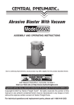
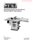
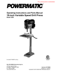
8 GALL
ON 2 HP
GALLON
AIR COMPRESSOR
Model 95386
OPERATING INSTRUCTIONS
Due to continuing improvements, actual product may differ slightly from the product described herein.
3491 Mission Oaks Blvd., Camarillo, CA 93011
Visit our Web site at: http://www.harborfreight.com
Copyright© 2006 by Harbor Freight Tools®. All rights reserved. No portion of this
manual or any artwork contained herein may be reproduced in any shape or form
without the express written consent of Harbor Freight Tools.
For technical questions, please call 1-800-444-3353.
PRODUCT SPECIFICATIONS
Item
Electrical Requirements
Description
2 HP Motor, 120 V / 60 Hz / 3360 RPM
15.5 Amps star tup, 7.4 Amps running
5'-4-1/2" long Power Cord - 14AWGX3C
Maximum Working PSI
115 PSI
Pump Style
Single Cylinder Pump
Air Delivery
6.0 CFM @ 40 PSI, 5.0 CFM @ 90 PSI , 4.2 CFM
@115 PSI
Air Tank Capacity
8 Gallons
Automatic Pressure Controls
Automatic Shut-Off @ 115 PSI
Automatic Restar t @ 80 PSI
Air Outlet Size
1/4"-18 NPT Female Threads
Net Weight
55 Pounds
®
C
US
SAVE THIS MANUAL
You will need this manual for the safety warnings and precautions, assembly, operating,
inspection, maintenance and cleaning procedures, parts list and assembly diagram.
Keep your invoice with this manual. Write the invoice number on the inside of the
front cover. Keep this manual and invoice in a safe and dry place for future reference.
GENERAL SAFETY RULES
WARNING!
READ AND UNDERSTAND ALL INSTRUCTIONS
Failure to follow all instructions listed below may result in
electric shock, fire, and/or serious injury.
SAVE THESE INSTRUCTIONS
WORK AREA
1.
Keep your work area clean and well lit. Cluttered benches and dark areas
invite accidents.
SKU 95386
For technical questions, please call 1-800-444-3353.
Page 2
2.
Do not operate power tools in explosive atmospheres, such as in the
presence of flammable liquids, gases, or dust. Power tools create sparks
which may ignite the dust or fumes.
3.
Keep bystanders, children, and visitors away while operating a power tool.
Distractions can cause you to lose control. Protect others in the work area from
debris such as chips and sparks. Provide barriers or shields as needed. Never
allow children in the work area.
ELECTRICAL SAFETY
4.
Grounded tools must be plugged into an outlet properly installed and
grounded in accordance with all codes and ordinances. Never remove the
grounding prong or modify the plug in any way. Do not use any adapter
plugs. Check with a qualified electrician if you are in doubt as to whether
the outlet is properly grounded. If the tools should electrically malfunction or
break down, grounding provides a low resistance path to carry electricity away
from the user.
5.
Double insulated tools are equipped with a polarized plug (one blade is
wider than the other). This plug will fit in a polarized outlet only one way. If
the plug does not fit fully in the outlet, reverse the plug. If it still does not
fit, contact a qualified electrician to install a polarized outlet. Do not
eliminates the need for the
change the plug in any way. Double insulation
three wire grounded power cord and grounded power supply system.
6.
Avoid body contact with grounded surfaces such as pipes, radiators,
ranges, and refrigerators. There is an increased risk of electric shock if your
body is grounded.
7.
Do not expose power tools to rain or wet conditions. Water entering a power
tool will increase the risk of electric shock.
8.
Do not abuse the Power Cord. Never use the Power Cord to carry the tools
or pull the Plug from an outlet. Keep the Power Cord away from heat, oil,
sharp edges, or moving parts. Replace damaged Power Cords immediately.
Damaged Power Cords increase the risk of electric shock.
PERSONAL SAFETY
9.
Stay alert. Watch what you are doing, and use common sense when
operating a power tool. Do not use a power tool while tired or under the
influence of drugs, alcohol, or medication. A moment of inattention while
operating power tools may result in serious personal injury.
SKU 95386
For technical questions, please call 1-800-444-3353.
Page 3
10.
Dress properly. Do not wear loose clothing or jewelry. Contain long hair.
Keep your hair, clothing, and gloves away from moving parts. Loose
clothes, jewelry, or long hair can be caught in moving parts.
11.
Avoid accidental starting. Be sure the Power Switch is off before plugging
in. Carrying power tools with your finger on the Power Switch, or plugging in
power tools with the Power Switch on, invites accidents.
12.
Remove adjusting keys or wrenches before turning the power tool on. A
wrench or a key that is left attached to a rotating part of the power tool may result
in personal injury.
13.
Do not overreach. Keep proper footing and balance at all times. Proper
footing and balance enables better control of the power tool in unexpected
situations.
14.
Use safety equipment. Always wear ANSI-approved eye and ear protection.
Dust mask, non-skid safety shoes, hard hat, or hearing protection must be used
for appropriate conditions.
TOOL USE AND CARE
15.
Do not force the tool. Use the correct tool for your application. The correct
tool will do the job better and safer at the rate for which it is designed.
16.
Do not use the power tool if the Power Switch does not turn it on or off.
Any tool that cannot be controlled with the Power Switch is dangerous and must
be replaced.
17.
Disconnect the Power Cord Plug from the power source before making any
adjustments, changing accessories, or storing the tool. Such preventive
safety measures reduce the risk of starting the tool accidentally.
18.
Store idle tools out of reach of children and other untrained persons. Tools
are dangerous in the hands of untrained users.
19.
Maintain tools with care. Keep cutting tools sharp and clean. Properly
maintained tools with a sharp cutting edge are less likely to bind and are easier
to control. Do not use a damaged tool. Tag damaged tools “Do not use” until
repaired.
SKU 95386
For technical questions, please call 1-800-444-3353.
Page 4
20.
Check for misalignment or binding of moving parts, breakage of parts, and
any other condition that may affect the tool’s operation. If damaged, have
the tool serviced before using. Many accidents are caused by poorly
maintained tools.
21.
Use only accessories that are recommended by the manufacturer for your
model. Accessories that may be suitable for one tool may become hazardous
when used on another tool.
SERVICE
22.
Tool service must be performed only by qualified repair personnel. Service
or maintenance performed by unqualified personnel could result in a risk of injury.
23.
When servicing a tool, use only identical replacement parts. Follow
instructions in the “Inspection, Maintenance, And Cleaning” section of this
manual. Use of unauthorized parts or failure to follow maintenance instructions
may create a risk of electric shock or injury.
GROUNDING
WARNING!
Improperly connecting the grounding wire can result in the risk of electric
shock. Check with a qualified electrician if you are in doubt as to whether the
outlet is properly grounded. Do not modify the power cord plug provided with
the tool. Never remove the grounding prong from the plug. Do not use the
tool if the power cord or plug is damaged. If damaged, have it repaired by a
service facility before use. If the plug will not fit the outlet, have a proper outlet
installed by a qualified electrician.
GROUNDED TOOLS: TOOLS WITH THREE PRONG PLUGS
1.
Tools marked with “Grounding Required” have a three wire cord and three prong
grounding plug. The plug must be connected to a properly grounded outlet. If the
tool should electrically malfunction or break down, grounding provides a low
resistance path to carry electricity away from the user, reducing the risk of electric
shock. (See Figure A.)
2.
The grounding prong in the plug is connected through the green wire inside the
cord to the grounding system in the tool. The green wire in the cord must be the only
wire connected to the tool’s grounding system and must never be attached to an
electrically “live” terminal. (See Figure A.)
SKU 95386
For technical questions, please call 1-800-444-3353.
Page 5
3.
Your tool must be plugged into an appropriate outlet, properly installed and grounded
in accordance with all codes and ordinances. The plug and outlet should look like
those in the following illustration. (See Figure A.)
FIGURE A
NOTE: This product has a 3-prong, grounded electrical plug
DOUBLE INSULATED TOOLS: TOOLS WITH TWO PRONG PLUGS
4.
Tools marked “Double Insulated” do not require grounding. They have a special
double insulation system which satisfies OSHA requirements and complies with
the applicable standards of Underwriters Laboratories, Inc., the Canadian Standard
Association, and the National Electrical Code. (See Figure B.)
5.
Double insulated tools may be used in either of the 120 volt outlets shown in the
following illustration. (See Figure B.)
FIGURE B
SKU 95386
For technical questions, please call 1-800-444-3353.
Page 6
EXTENSION CORDS
1.
Grounded tools require a three wire extension cord. Double Insulated tools can
use either a two or three wire extension cord.
2.
As the distance from the supply outlet increases, you must use a heavier gauge
extension cord. Using extension cords with inadequately sized wire causes a serious
drop in voltage, resulting in loss of power and possible tool damage.
(See Figure C, next page.)
3.
The smaller the gauge number of the wire, the greater the capacity of the cord. For
example, a 14 gauge cord can carry a higher current than a 16 gauge cord.
(See Figure C.)
4.
When using more than one extension cord to make up the total length, make sure
each cord contains at least the minimum wire size required. (See Figure C.)
5.
If you are using one extension cord for more than one tool, add the nameplate
amperes and use the sum to determine the required minimum cord size.
(See Figure C.)
6.
If you are using an extension cord outdoors, make sure it is marked with the suffix
“W-A” (“W” in Canada) to indicate it is acceptable for outdoor use.
7.
Make sure your extension cord is properly wired and in good electrical condition.
Always replace a damaged extension cord or have it repaired by a qualified
electrician before using it.
8.
Protect your extension cords from sharp objects, excessive heat, and damp or wet
areas.
RECOMMENDED MINIMUM WIRE GAUGE FOR EXTENSION CORDS*
NAMEPLATE
AMPERES
(At Full Load)
EXTENSION CORD LENGTH
25 Feet
50 Feet
75 Feet
100 Feet
150 Feet
0 - 2.0
18
18
18
18
16
2.1 - 3.4
18
18
18
16
14
3.5 - 5.0
18
18
16
14
12
5.1 - 7.0
18
16
14
12
12
7.1 - 12.0
18
14
12
10
-
12.1 - 16.0
14
12
10
-
-
16.1 - 20.0
12
10
-
-
-
FIGURE C
SKU 95386
* Based on limiting the line voltage drop to five
volts at 150% of the rated amperes.
For technical questions, please call 1-800-444-3353.
Page 7
SYMBOLOGY
SPECIFIC SAFETY RULES
1.
Maintain a safe working environment. Keep the work area well lit. Make sure
there is adequate surrounding workspace. Always keep the work area free of
obstructions, grease, oil, trash, and other debris. Do not use this product in areas
near flammable chemicals, gasoline, dusts and vapors.
2.
Maintain labels and nameplates on the Air Compressor. These carry
important information. If unreadable or missing, contact Harbor Freight Tools for a
replacement.
3.
Use eye and hearing protection. Always wear ANSI-approved safety impact
eye goggles and hearing protectors when using this product.
4.
Do not allow children to use or play with this product.
5.
Store idle equipment. When not in use, tools and equipment should be stored in
a dry location to inhibit rust. Always lock up tools and equipment, and keep out of
reach of children.
6.
Do not use this product if under the influence of alcohol or drugs. Read
warning labels on prescriptions to determine if your judgement or reflexes are
impaired while taking drugs. If there is any doubt, do not attempt to use this
product.
7.
Make sure to fill the Air Compressor with a premium quality, 30-weight,
non-detergent, compressor oil before each use. Running the Air Compressor
with no oil or low oil will cause damage to the equipment and void the warranty.
SKU 95386
For technical questions, please call 1-800-444-3353.
Page 8
8.
When filling the Air Compressor with oil, make sure to unscrew (do not pull)
the Oil Plug (31) out.
9.
Do not allow moisture to build up inside the Air Tank (1). Drain water from the
tank daily. Do not open the Drain Valve (65) so that more than four threads are
showing.
10.
Avoid injury. Never direct the pressurized air stream at people or animals.
11.
Do not alter or remove the factory sealed Safety Valve (56).
12.
Dress properly. Do not wear loose clothing or jewelry as they can be caught in
moving parts. Wear restrictive hair covering to contain long hair.
13.
Do not overreach. Keep proper footing and balance at all times. Do not reach
over or across running machines.
14.
Industrial applications must follow OSHA requirements.
15.
Maintain this product with care. Keep this product clean for better and safer
performance.
16.
Maintenance: For your safety, service and maintenance should be performed
regularly by a qualified technician.
17.
Check for damaged parts. Before using this product, carefully check that it will
operate properly and perform its intended function. Check for damaged parts and
any other conditions that may affect the operation of this product. Replace or
repair damaged or worn parts immediately.
18.
Replacement parts and accessories: When servicing, use only identical
replacement parts. Only use accessories intended for use with this product.
19.
Use the right tool or attachment for the job. Do not attempt to force a small tool
or attachment to do the work of a larger industrial tool or attachment. There are
certain applications for which this product was designed. It will do the job better
and more safely at the rate for which it was intended. Do not modify this product,
and do not use this product for a purpose for which it was not intended.
20.
To extend the life of your air tools and equipment: It is recommended to install
a water filter and oiler (available from Harbor Freight Tools) in series with the Air
Outlet Valve (63) of the Air Compressor. (See Figure C, next page.)
21.
WARNING! People with pacemakers should consult their physician(s) before
using this product. Operation of electrical equipment in close proximity to a heart
pacemaker could cause interference or failure of the pacemaker.
22.
Do not leave the Air Compressor running while it is unattended.
SKU 95386
For technical questions, please call 1-800-444-3353.
Page 9
23.
WARNING! The warnings, precautions, and instructions discussed in this
manual cannot cover all possible conditions and situations that may occur. The
operator must understand that common sense and caution are factors which
cannot be built into this product, but must be supplied by the operator.
24.
WARNING! The brass components of this product contain lead, a chemical
known to the State of California to cause birth defects (or other reproductive
harm). (California Health & Safety code § 25249.5, et seq.)
TO:
AIR OUTLET
VALVE (63)
TO
AIR TOOL
OILER WATER
FIGURE C
UNPACKING
When unpacking, check to make sure all the parts shown on the Parts Lists on page 15
are included. If any parts are missing or broken, please call Harbor Freight Tools at the
number shown on the cover of this manual as soon as possible.
OPERATING INSTRUCTIONS
NOTE: For additional information regarding the parts mentioned in the following pages,
refer to the Assembly Diagrams on page 16.
1.
IMPORTANT! Always fill the Air Compressor with a premium quality,
30-weight, non-detergent, compressor oil before each use. Running the Air
Compressor with no oil or low oil will cause damage to the equipment and
void the warranty. To check the level of oil, make sure the Air Compressor is
OFF. Then, observe the Oil Sight Gauge (33). The level of oil should be within
the red circle on the Oil Sight Gauge (33). (See Figure D, next page) If the level of
oil is below the red circle, carefully unscrew and remove the Oil Plug (31) and
SKU 95386
For technical questions, please call 1-800-444-3353.
Page 10
add new oil through the oil fill holes. Make sure not to overfill. Screw on the Oil
Plug (31), being careful not to strip the threads.
OIL SIGHT
GAUGE
(33)
OIL PLUG
(31)
KEEP OIL LEVEL
EVEN WITH
RED CIRCLE
FIGURE E
FIGURE D
2.
Turn the Air Outlet Valve (63) to its CLOSED position. Then connect a high
pressure air hose (not included) equipped with a quick connector (not included) to
the Air Outlet Valve. If using a water filter and oiler in series with the Air Outlet
Valve of the Air Compressor, connect the other end of the air hose to the water
filter and oiler and connect the water filter and oiler to the air tool being used. If
not using a water filter and oiler, squirt several drops of air tool oil into the air
intake plug of the air tool. Then, connect the other end of the air hose directly from
the Air Outlet Valve of the Air Compressor to the air tool. (See Figure F.)
CLOSED POSITION
TOP VIEW
OPEN POSITION
AIR
OUTLET
VALVE
(63)
CONNECT
AIR HOSE HERE.
FIGURE F
SKU 95386
For technical questions, please call 1-800-444-3353.
Page 11
3.
Make sure the Drain Valve (65) is closed. (See Figure G.)
DRAIN
VALVE (65)
Figure G
ON/OFF
PRESSURE
SWITCH (55)
TANK
PRESSURE
GAUGE (54)
OUTLET
PRESSURE
GAUGE
(60)
AIR OUTLET
VALVE (63)
FIGURE H
4.
Make sure the “On/Off” Pressure Switch (55) is DOWN in its OFF position. Then,
plug the Power Cord (64) into the nearest 120 volt, grounded, electrical outlet.
(See Figure H.)
5.
Pull UP on “On/Off” Pressure Switch (55) to start the Compressor. (See Figure H.)
6.
Allow the Compressor to build up from 80 PSI to 115 PSI as indicated on the Tank
Pressure Gauge (54). Set the appropriate air pressure output for the air tool being
used. Pull out and then turn the pressure adjustment knob above the Outlet
Pressure Gauge (60) to the left to increase output air pressure or to the right to
decrease output air pressure. Once the pressure level reaches the recommended
SKU 95386
For technical questions, please call 1-800-444-3353.
Page 12
PSI of the tool on the Output Pressure Gauge (60), push in the knob to set the
output pressure. (See Figure H.)
7.
As long as the “On/Off” Pressure Switch (55) is in its ON position the operation of
the Compressor is automatic, controlled by an internal pressure switch. The
Compressor will turn on automatically when the air pressure drops to 80 PSI as
indicated on the Pressure Gauge (54), and will turn off automatically when the air
pressure reaches 115 PSI as indicated. IMPORTANT: The internal pressure
switch is not user adjustable, never make changes to the air pressure levels.
Any change to the automatic pressure levels may cause excess pressure to
accumulate, causing a hazardous situation.
8.
NOTE: If it is necessary to quickly depressurize the Compressor, turn off the Air
Compressor by pushing DOWN on the “On/Off” Pressure Switch (55). Then, pull
OUT on the ring on the Safety Valve (56) to quickly release stored air pressure.
9.
When finished using the Air Compressor, turn it off by pushing DOWN on the
”On/Off” Pressure Switch (55). Unplug the Power Cord (64) from its electrical
outlet. Squeeze the trigger on the air tool being used to release all stored air
pressure from the system, and disconnect the air hose and air tool from the Air
Compressor. Then, open the Drain Valve (65) to release all remaining
compressed air from the Tank (1). Note: Accumulated mositure will also be
discharged. (See Figure G.)
10.
NOTE: The Compressor is equipped with a Reset Button (19). (See Figure I.)
Should the Compressor overheat while in use, the machine will automatically
shut down. If this happens, push DOWN on the “On/Off” Pressure Switch (55).
Wait for the unit to cool off (usually 5-10 minutes). Then, press the Reset Button
(19) and pull UP on the “On/Off” Pressure Switch (55) to restart the Compressor. If
overheating is a reoccurring problem, make certain that the extension cord used
is of the proper gauge and length for this unit’s power requirements - as explained
on page 7.
RESET
BUTTON (19)
Figure I
SKU 95386
For technical questions, please call 1-800-444-3353.
Page 13
INSPECTION AND MAINTENANCE
1.
WARNING! Always unplug the Air Compressor from its electrical outlet
before performing any inspection, maintenance, or cleaning.
2.
Before each use: Inspect the general condition of the Air Compressor. Check for
misalignment or binding of moving parts, cracked or broken parts, damaged
wiring, damaged air hose, and any other condition that may affect its safe
operation. If abnormal noise or vibration occurs, have the problem corrected
before further use. Do not use damaged equipment.
3.
Daily, before switching the compressor on: Make sure the level of compressor
oil is adequate. For instructions on checking and, if necessary, filling the Air
Compressor with oil, see pages 10 and 11 of this manual.
4.
Daily: Purge the Tank (1) daily of all air and moisture to prevent corrosion. To do
so, unscrew the Drain Valve (65) two to three turns. Do not unscrew the Drain
Valve more than three turns. When all the air pressure and moisture is released
from the Tank, retighten the Tank Drain Valve. (See Figure G.)
5.
Store the Air Compressor in a clean, dry, location.
WARRANTY
LIMITED 1 YEAR/
90 DAY WARRANTY
Harbor Freight Tools Co. makes every effort to assure that its products meet high quality and durability standards,
and warrants to the original purchaser that for a period of one year from date of purchase that the tank is free of
defects in materials and workmanship. Harbor Freight Tools also warrants to the original purchaser, for a period
of ninety days from date of purchase, that all other parts and components of the product are free from defects in
materials and workmanship. This warranty does not apply to damage due directly or indirectly to misuse, abuse,
negligence or accidents; repairs or alterations outside our facilities; or to lack of maintenance. We shall in no
event be liable for death, injuries to persons or property, or for incidental, contingent, special or consequential
damages arising from the use of our product. Some states do not allow the exclusion or limitation of incidental
or consequential damages, so the above limitation of exclusion may not apply to you. THIS WARRANTY IS
EXPRESSLY IN LIEU OF ALL OTHER WARRANTIES, EXPRESS OR IMPLIED, INCLUDING THE WARRANTIES
OF MERCHANTABILITY AND FITNESS.
To take advantage of this warranty, the product or part must be returned to us with transportation charges prepaid.
Proof of purchase date and an explanation of the complaint must accompany the merchandise. If our inspection
verifies the defect, we will either repair or replace the product at our election or we may elect to refund the purchase
price if we cannot readily and quickly provide you with a replacement. We will return repaired products at our
expense, but if we determine there is no defect, or that the defect resulted from causes not within the scope of
our warranty, then you must bear the cost of returning the product.
This warranty gives you specific legal rights and you may also have other rights which vary from state to state.
3491 Mission Oaks Blvd. • PO Box 6009 • Camarillo, CA 93011 • (800) 444-3353
SKU 95386
For technical questions, please call 1-800-444-3353.
Page 14
PARTS LIST
Part #
1
2
3
4
5
6
7
8
9
10
11
12
13
14
15
16
17
18
19
20
21
22
23
24
25
26
27
28
29
30
31
32
33
34
SKU 95386
Description
Air tank
M8 nut
Spring washer 8
Flat washer
Wheel assembly
Wheel shaft screw
O-sealed washer
Tank cap
Sealed washer
Exhaust pipe assembly
Spring washer
Protection Cover
Fan
Black motor cover
Wave washer
Bearing 6202-RZ
Screw M5x105
Stator
Reset button
Rotator assembly
Capacitor
Serrated washer 8
Screw M5x10
Bearing 6204-RZ
Oil Seal B20x40
Screw M12x12
Crankcase
Crank
Screw M12x12
Crankcase cover gasket
Oil plug
Crankcase cover
Oil sight gauge
Screw M5x12
Part #
35
36
37
38
39
40
41
42
43
44
45
46
47
48
49
50
51
52
53
54
55
56
57
58
59
60
61
62
63
64
65
66
67
Description
Handle
Cylinder gasket
Connecting rod
Piston
Oil clean ring
Seal ring
Cylinder
Valve plate gasket
Right-angle connector
Screw M8x105
Air filter
Cylinder cover
Cylinder gasket
Valve plate assembly
Limit pin
Air intake valve
Piston pin
Circlip
Lock nut
Tank pressure gauge
Pressure switch
Safety valve
Connector
Regulator assembly
Quick coupling
Output Pressure Gauge
Screw M8x30
Unload pipe
Outlet valve
Cord and plug
Drain valve
Rubber foot
Screw M8x25
For technical questions, please call 1-800-444-3353.
Page 15
ASSEMBLY DIAGRAM
Note: Some parts are listed and shown for illustration purposes only and are not available individually as replacement parts.
PLEASE READ THE FOLLOWING CAREFULLY
THE MANUFACTURER AND/OR DISTRIBUTOR HAS PROVIDED THE PARTS LIST AND ASSEMBLY DIAGRAM IN THIS
MANUAL AS A REFERENCE TOOL ONLY. NEITHER THE MANUFACTURER OR DISTRIBUTOR MAKES ANY
REPRESENTATION OR WARRANTY OF ANY KIND TO THE BUYER THAT HE OR SHE IS QUALIFIED TO MAKE ANY
REPAIRS TO THE PRODUCT, OR THAT HE OR SHE IS QUALIFIED TO REPLACE ANY PARTS OF THE PRODUCT. IN
FACT, THE MANUFACTURER AND/OR DISTRIBUTOR EXPRESSLY STATES THAT ALL REPAIRS AND PARTS
REPLACEMENTS SHOULD BE UNDERTAKEN BY CERTIFIED AND LICENSED TECHNICIANS, AND NOT BY THE BUYER.
THE BUYER ASSUMES ALL RISK AND LIABILITY ARISING OUT OF HIS OR HER REPAIRS TO THE ORIGINAL PRODUCT
OR REPLACEMENT PARTS THERETO, OR ARISING OUT OF HIS OR HER INSTALLATION OF REPLACEMENT PARTS
THERETO.
SKU 95386
For technical questions, please call 1-800-444-3353.
Page 16